EP4401206B1 - Energiespeichervorrichtung mit batterieendabdeckungsanordnung, und elektrische vorrichtung - Google Patents
Energiespeichervorrichtung mit batterieendabdeckungsanordnung, und elektrische vorrichtung Download PDFInfo
- Publication number
- EP4401206B1 EP4401206B1 EP23208852.6A EP23208852A EP4401206B1 EP 4401206 B1 EP4401206 B1 EP 4401206B1 EP 23208852 A EP23208852 A EP 23208852A EP 4401206 B1 EP4401206 B1 EP 4401206B1
- Authority
- EP
- European Patent Office
- Prior art keywords
- end cover
- pressure relief
- area
- relief mechanism
- battery
- Prior art date
- Legal status (The legal status is an assumption and is not a legal conclusion. Google has not performed a legal analysis and makes no representation as to the accuracy of the status listed.)
- Active
Links
Images

Classifications
-
- H—ELECTRICITY
- H01—ELECTRIC ELEMENTS
- H01M—PROCESSES OR MEANS, e.g. BATTERIES, FOR THE DIRECT CONVERSION OF CHEMICAL ENERGY INTO ELECTRICAL ENERGY
- H01M50/00—Constructional details or processes of manufacture of the non-active parts of electrochemical cells other than fuel cells, e.g. hybrid cells
- H01M50/30—Arrangements for facilitating escape of gases
- H01M50/342—Non-re-sealable arrangements
- H01M50/3425—Non-re-sealable arrangements in the form of rupturable membranes or weakened parts, e.g. pierced with the aid of a sharp member
-
- H—ELECTRICITY
- H01—ELECTRIC ELEMENTS
- H01M—PROCESSES OR MEANS, e.g. BATTERIES, FOR THE DIRECT CONVERSION OF CHEMICAL ENERGY INTO ELECTRICAL ENERGY
- H01M50/00—Constructional details or processes of manufacture of the non-active parts of electrochemical cells other than fuel cells, e.g. hybrid cells
- H01M50/10—Primary casings; Jackets or wrappings
- H01M50/102—Primary casings; Jackets or wrappings characterised by their shape or physical structure
- H01M50/103—Primary casings; Jackets or wrappings characterised by their shape or physical structure prismatic or rectangular
-
- H—ELECTRICITY
- H01—ELECTRIC ELEMENTS
- H01M—PROCESSES OR MEANS, e.g. BATTERIES, FOR THE DIRECT CONVERSION OF CHEMICAL ENERGY INTO ELECTRICAL ENERGY
- H01M50/00—Constructional details or processes of manufacture of the non-active parts of electrochemical cells other than fuel cells, e.g. hybrid cells
- H01M50/10—Primary casings; Jackets or wrappings
- H01M50/147—Lids or covers
- H01M50/148—Lids or covers characterised by their shape
- H01M50/15—Lids or covers characterised by their shape for prismatic or rectangular cells
-
- H—ELECTRICITY
- H01—ELECTRIC ELEMENTS
- H01M—PROCESSES OR MEANS, e.g. BATTERIES, FOR THE DIRECT CONVERSION OF CHEMICAL ENERGY INTO ELECTRICAL ENERGY
- H01M50/00—Constructional details or processes of manufacture of the non-active parts of electrochemical cells other than fuel cells, e.g. hybrid cells
- H01M50/10—Primary casings; Jackets or wrappings
- H01M50/172—Arrangements of electric connectors penetrating the casing
- H01M50/174—Arrangements of electric connectors penetrating the casing adapted for the shape of the cells
- H01M50/176—Arrangements of electric connectors penetrating the casing adapted for the shape of the cells for prismatic or rectangular cells
-
- H—ELECTRICITY
- H01—ELECTRIC ELEMENTS
- H01M—PROCESSES OR MEANS, e.g. BATTERIES, FOR THE DIRECT CONVERSION OF CHEMICAL ENERGY INTO ELECTRICAL ENERGY
- H01M50/00—Constructional details or processes of manufacture of the non-active parts of electrochemical cells other than fuel cells, e.g. hybrid cells
- H01M50/50—Current conducting connections for cells or batteries
- H01M50/543—Terminals
- H01M50/547—Terminals characterised by the disposition of the terminals on the cells
- H01M50/55—Terminals characterised by the disposition of the terminals on the cells on the same side of the cell
-
- H—ELECTRICITY
- H01—ELECTRIC ELEMENTS
- H01M—PROCESSES OR MEANS, e.g. BATTERIES, FOR THE DIRECT CONVERSION OF CHEMICAL ENERGY INTO ELECTRICAL ENERGY
- H01M50/00—Constructional details or processes of manufacture of the non-active parts of electrochemical cells other than fuel cells, e.g. hybrid cells
- H01M50/50—Current conducting connections for cells or batteries
- H01M50/543—Terminals
- H01M50/552—Terminals characterised by their shape
- H01M50/553—Terminals adapted for prismatic, pouch or rectangular cells
-
- H—ELECTRICITY
- H01—ELECTRIC ELEMENTS
- H01M—PROCESSES OR MEANS, e.g. BATTERIES, FOR THE DIRECT CONVERSION OF CHEMICAL ENERGY INTO ELECTRICAL ENERGY
- H01M50/00—Constructional details or processes of manufacture of the non-active parts of electrochemical cells other than fuel cells, e.g. hybrid cells
- H01M50/60—Arrangements or processes for filling or topping-up with liquids; Arrangements or processes for draining liquids from casings
- H01M50/609—Arrangements or processes for filling with liquid, e.g. electrolytes
- H01M50/627—Filling ports
-
- H—ELECTRICITY
- H01—ELECTRIC ELEMENTS
- H01M—PROCESSES OR MEANS, e.g. BATTERIES, FOR THE DIRECT CONVERSION OF CHEMICAL ENERGY INTO ELECTRICAL ENERGY
- H01M2220/00—Batteries for particular applications
- H01M2220/20—Batteries in motive systems, e.g. vehicle, ship, plane
-
- Y—GENERAL TAGGING OF NEW TECHNOLOGICAL DEVELOPMENTS; GENERAL TAGGING OF CROSS-SECTIONAL TECHNOLOGIES SPANNING OVER SEVERAL SECTIONS OF THE IPC; TECHNICAL SUBJECTS COVERED BY FORMER USPC CROSS-REFERENCE ART COLLECTIONS [XRACs] AND DIGESTS
- Y02—TECHNOLOGIES OR APPLICATIONS FOR MITIGATION OR ADAPTATION AGAINST CLIMATE CHANGE
- Y02E—REDUCTION OF GREENHOUSE GAS [GHG] EMISSIONS, RELATED TO ENERGY GENERATION, TRANSMISSION OR DISTRIBUTION
- Y02E60/00—Enabling technologies; Technologies with a potential or indirect contribution to GHG emissions mitigation
- Y02E60/10—Energy storage using batteries
Definitions
- the present application relates to the technical field of batteries, in particular to a battery end cover assembly, an energy storage apparatus and an electric device.
- each of a mobile phone, a notebook computer, an electric tool, an electric vehicle, etc. adopts batteries as a power source, for example, the electric vehicle needs to adopt a power battery pack composed of a plurality of batteries.
- a battery is provided with an anti-explosion and pressure relief structure on a cover plate, for example, the cover plate of the battery is provided with a thin-walled valve body, when an internal pressure of the battery exceeds a specified value, a thin wall of the valve body ruptures to release the internal pressure, and thus, the battery is prevented from being exploded and fractured.
- the anti-explosion and pressure relief structure is relatively constant in specification and has the situation of untimely pressure relief caused by overhigh relief pressure, and thus, the safety of the battery is affected.
- CN212571194U describes a secondary battery which comprises a shell, a first cover plate and a second cover plate, the shell is of a cylindrical structure, a first opening and a second opening which are opposite to each other are formed in the extending direction of the shell, the first cover plate covers the first opening, the second cover plate covers the second opening, a first explosion-proof valve is arranged on the first cover plate, and a second explosion-proof valve is arranged on the second cover plate.
- CN213340640U discloses a rectangular battery cell including an end cover assembly having an end cover, electrode terminals and a pressure relief valve mechanism mounted on a hole of the end cover.
- US2015/280191A1 discloses a rectangular battery cell including an electrode assembly enclosed in a case and covered by a lid.
- the present application provides a battery end cover assembly by which the area taken up by a pressure relief mechanism is more matched with the area of an end cover, and thus, the battery end cover assembly is matched with the pressure relief capacity of a battery.
- the present application further provides an electric device adopting the above-mentioned energy storage apparatus.
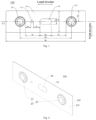
- the battery end cover assembly includes an end cover of a rectangle; terminal assemblies, the terminal assemblies being connected to the end cover; and a pressure relief mechanism, the pressure relief mechanism being disposed on the end cover, and the pressure relief mechanism and the terminal assemblies being distributed at intervals in the length direction of the end cover; wherein the area of a figure formed by an outer contour of the end cover is a first area S1, the area of a projection of the pressure relief mechanism on the end cover is a second area S2, and the second area S2 accounts for 0.5% to 5% of the first area S1.
- the size of the pressure relief mechanism in the length direction of the end cover is b1, and b1 accounts for 5% to 12% of the length b0 of the end cover; and the size of the pressure relief mechanism in the width direction of the end cover is e1, and e1 accounts for 15% to 25% of the width e0 of the end cover.
- An area of the preset opening area is at least a half of the second area S2 and not more than 95% of the second area S2.
- a ratio of a capacity a of the energy storage apparatus to the second area is at least equal to 1.8, wherein the unit of the capacity a is ampere-hour (AH), and the unit of the second area S2 is mm 2 .
- the energy storage apparatus includes the battery end cover assembly according to the above-mentioned embodiment.
- the electric device includes the energy storage apparatus according to the above-mentioned embodiment.
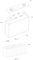
- a battery end cover assembly 100 includes an end cover 10, terminal assemblies 20 and a pressure relief mechanism 50, and the terminal assemblies 20 and the pressure relief mechanism 50 are both disposed on the end cover 10.
- the end cover 10 is an end sealing cover of a battery, and the terminal assemblies 20 are used for internal and external electric energy transmission of the battery.
- the pressure relief mechanism 50 is a component for relieving an internal pressure of the battery.
- the pressure relief mechanism 50 is disposed on the end cover 10, and when the internal pressure or temperature of the battery reaches a threshold value, the internal pressure of the battery is relieved by the pressure relief mechanism 50.
- the pressure relief mechanism 50 may be a component such as an anti-explosion valve 51, an anti-explosion sheet, a pressure relief valve and a one-way valve.
- the end cover 10 is provided with terminal leading-out holes 13 penetrating in the thickness direction thereof, and the terminal assemblies 20 are connected to the end cover 10 and cover the terminal leading-out holes 13.
- the terminal assemblies 20 cover the terminal leading-out holes 13 to play a role in sealing the terminal leading-out holes 13.
- the end cover 10 is not provided with the terminal leading-out holes 13, and the terminal assemblies 20 are integrally formed on the end cover 10.
- the pressure relief mechanism 50 is located on a geometric center of a figure formed by an outer contour of the end cover 10.
- the end cover 10 is of a rectangle, and the pressure relief mechanism 50 is located on the intersection point of diagonal lines of the rectangle.
- the distance from the pressure relief mechanism 50 to each position of the edge of the end cover 10 is relatively balanced, and an exhaust path from the inside of the battery to the pressure relief mechanism 50 is relatively short as a whole, which is beneficial to the improvement of a pressure relief effect, so that the situation of untimely pressure relief caused by an overlong distance between a partial position inside the battery and the pressure relief mechanism 50 is avoided, and the probability of partial explosion caused by untimely pressure relief is reduced.
- the pressure relief mechanism 50 is not disposed in the center of the end cover 10, at the moment, the distance between the pressure relief mechanism 50 and the edge of the end cover 10 is also required to be reasonably set.
- the area of the figure formed by the outer contour of the end cover 10 is a first area S1
- the area of a projection of the pressure relief mechanism 50 on the end cover 10 is a second area S2
- the second area S2 accounts for 0.5% to 5% of the first area S1.
- the second area S2 is controlled to be 0.5% to 5% of the first area S1.
- the pressure relief mechanism 50 is a weak area on the battery end cover assembly 100, the pressure relief mechanism 50 is provided with a thin wall (or a structure such as a notch or a flexible membrane), when the internal pressure of temperature of the battery reaches the threshold value, the thin wall (or the structure such as the notch or the flexible membrane) is opened or torn off to release the internal pressure, and thus, the battery is prevented from being exploded or fractured. Therefore, the area of the pressure relief mechanism 50 on the end cover 10 not only can determine the pressure relief capacity, but also can affect the overall structural strength of the battery end cover assembly 100.
- the proportion of the second area S2 to the first area S1 to be not less than 0.5%, the area taken up by the pressure relief mechanism 50 cannot be too small, there is a pressure relief opening large enough for exhaust after the pressure relief mechanism 50 is opened, so that the size of the battery end cover assembly 100 is relatively matched with the pressure relief capacity. In this way, the probability of untimely pressure relief is reduced, and the safety of a battery is improved.
- the area taken up by the pressure relief mechanism 50 cannot be too large, in this way, the overall structural strength of the battery end cover assembly 100 can be guaranteed, and the battery end cover assembly is not easy to deform after bearing a pressure.
- the edge, on the pressure relief mechanism 50, of the end cover 10 is also not easy to deform, so that the probability that the pressure relief mechanism 50 falls off to be invalid is reduced, and the reliability of the overall battery can be improved.
- the proportion of the second area S2 to the first area S1 may be 0.8%, 1.0%, 1.2%, 1.3%, 1.5%, 1.7%, 2.1%, 2.3%, 2.5%, 2.8%, 3.0%, 3.4%, 3.7%, 3.9%, 4.1%, 4.3%, 4.5%, 4.8% and 5.0%.
- a battery end cover assembly 100 of the present application includes an end cover 10, terminal assemblies 20 and a pressure relief mechanism 50, and the terminal assemblies 20 and the pressure relief mechanism 50 are both disposed on the end cover 10.
- the pressure relief mechanism 50 and the terminal assemblies 20 are distributed at intervals in the length direction of the end cover 10.
- the size of the pressure relief mechanism 50 in the length direction of the end cover 10 is b1 which is referred to as the length of the pressure relief mechanism 50, and the length b1 of the pressure relief mechanism 50 accounts for 5% to 12% of the length b0 of the end cover 10.
- the size of the pressure relief mechanism 50 in the width direction of the end cover 10 is e1 which is referred to as the width of the pressure relief mechanism 50, and the width e1 of the pressure relief mechanism 50 accounts for 15% to 25% of the width e0 of the end cover 10.
- the pressure relief mechanism 50 is a weak area on the battery end cover assembly 100, the pressure relief mechanism 50 may be extruded when the internal pressure of the battery is overhigh, and thus, the battery end cover assembly 100 deforms to a certain extent.
- the pressure relief mechanism 50 is spaced from the terminal assemblies 20 in the length direction of the end cover 10.
- the terminal assemblies 20 can keep away from the pressure relief mechanism 50, the centralized stresses on the terminal assemblies 20 are relatively small when the internal pressure of the battery is relatively high, and thus, loss, connection falling off, etc. caused by overhigh pressure borne by the terminal assemblies 20 are avoided.
- the length size of the end cover 10 can be utilized, and the pressure relief mechanism 50 may be spaced from the terminal assemblies 20 for a certain distance, so that mutual interference and influences to each other are avoided.
- the pressure relief mechanism 50 can take up an area large enough for pressure relief and exhaust, thereby guaranteeing the smoothness of exhaust.
- the proportion of the length b1 of the pressure relief mechanism 50 to the length b0 of the end cover 10 By controlling the proportion of the length b1 of the pressure relief mechanism 50 to the length b0 of the end cover 10 to be not more than 12%, a distance which is long enough can be reserved between two sides, located on the pressure relief mechanism 50, of the end cover 10 to place structures such as the terminal assemblies 20.
- the proportion of the width e1 of the pressure relief mechanism 50 to the width e0 of the end cover 10 to be not more than 25%, the probability that the side, located on the pressure relief mechanism 50, of the end cover 10 is too narrow to be easily fractured is reduced.
- the length and width of the pressure relief mechanism 50 By controlling the length and width of the pressure relief mechanism 50, the structural strength of the end cover 10 can be guaranteed while the pressure relief capacity can be guaranteed, and the situation that the end cover 10 is bent and fractured when bearing an impact and a pressure is avoided.
- the length b1 of the pressure relief mechanism 50 is limited to avoid excessive deformation caused by an overlarge bending moment borne due to the overlarge length of the pressure relief mechanism 50, so that the situation that the pressure relief mechanism 50 is easy to fall off due to the excessive deformation is avoided, in this way, the problems that the exhaust direction cannot be limited and the exhaust is obstructed by the separated pressure relief mechanism 50 due to the fact that the pressure relief mechanism 50 is ejected away from the end cover 10 by a high-pressure gas at high pressure are also avoided.
- the proportion of the area of the pressure relief mechanism 50 to the area of the end cover 10 is 0.5% to 5%
- the proportion of the length of the pressure relief mechanism 50 to the length of the end cover 10 i.e. the proportion of the length b1 to the length b0
- the proportion of the width of the pressure relief mechanism 50 to the width of the end cover 10 i.e. the proportion of the width e1 to the width e0
- the pressure relief mechanism 50 can take up an area large enough for pressure relief and exhaust, thereby guaranteeing smooth and timely exhaust.
- each side, located on the pressure relief mechanism 50, of the end cover 10 does not have to be set to be too narrow, so that the risk that the edge of the end cover 10 is easily fractured due to the overlarge length and width of the pressure relief mechanism 50 is avoided, and the situation that the end cover 10 is bent and fractured when bearing an impact and a pressure is avoided. Moreover, there is a sufficient space for arranging components on the end cover 10 so that all the components can be spaced without mutual interference.
- the proportion of the length b1 of the pressure relief mechanism 50 to the length b0 of the end cover 10 is 5%, 7%, 9%, 10%, 11.5%, 12%, etc.
- the proportion of the width e1 of the pressure relief mechanism 50 to the width e0 of the end cover 10 is 15%, 17%, 19%, 20%, 21.5%, 22.4%, 23.7%, 24.8%, 25%, etc.
- a battery end cover assembly 100 includes an end cover 10, terminal assemblies 20 and a pressure relief mechanism 50, and the terminal assemblies 20 and the pressure relief mechanism 50 are both disposed on the end cover 10.
- the size of the pressure relief mechanism 50 in the length direction of the end cover 10 is b1
- the minimum distance between the pressure relief mechanism 50 and each of the terminal assemblies 20 is b2, and b2>b1.
- the pressure relief mechanism 50 After the pressure relief mechanism 50 is opened, the pressure relief mechanism 50 is not easily blocked by the other external components, the probability that the internal gas and the electrolyte are ejected on the terminal assemblies 20 and the other external components when the pressure relief mechanism 50 performs pressure relief can be reduced, and the probability that the other external components catch fire is reduced. Moreover, after the pressure relief mechanism 50 is spaced from the terminal assemblies 20 for a safe distance, the risk of short circuit caused by conducting the positive and negative electrodes of the battery by an ejected material from the pressure relief mechanism 50 is not easily caused, and therefore, the safety of the battery can be improved.
- the minimum distance between the pressure relief mechanism 50 and each of the terminal assemblies 20 is b2, the length of the pressure relief mechanism 50 is b1, and 25% ⁇ b1/b2 ⁇ 35%.
- the distance between the pressure relief mechanism 50 and each of the terminal assemblies 20 can be long enough, and therefore, the risk that the ejected material from the pressure relief mechanism 50 is ejected to the terminal assemblies 20 is further reduced.
- the pressure relief mechanism 50 and the terminal assemblies 20 are reasonably distributed on the end cover 10, so that interference generated by disposing the terminal assemblies 20 to be too close to the edge of the end cover 10 is avoided.
- the terminal assemblies 20 are closer to the edge of the end cover 10 with respect to the pressure relief mechanism 50. As the edge of the end cover 10 is supported, the structural strength on the positions of the terminal assemblies 20 can be improved by virtue of the support borne by the edge of the end cover 10, pressures borne on the terminal assemblies 20 when the battery end cover assembly 10 bears a pressure can be reduced, and the probability that the terminal assemblies 20 are damaged to fall off can be reduced.
- b1/b2 may be 25%, 27.1%, 29.6%, 31.2%, 33.1%, 34.5%, 35%, etc.
- a battery end cover assembly 100 the present application includes an end cover 10, terminal assemblies 20 and a pressure relief mechanism 50, and the terminal assemblies 20 and the pressure relief mechanism 50 are both disposed on the end cover 10.
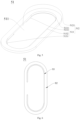
- the pressure relief mechanism 50 includes an anti-explosion valve 51
- the anti-explosion valve 51 includes a preset opening area 511.
- the outer edge of the preset opening area 511 is referred to as a predetermined open boundary 512.
- the preset opening area 511 is an area reserved for pressure relief when the anti-explosion valve 51 is designed. If pressure relief is required when the internal temperature or pressure of the battery is increased, the preset opening area 511 is opened, so that a pressure relief opening is formed in the anti-explosion valve 51, and the gas in the battery is exhausted from the pressure relief opening formed after the preset opening area 511 is opened.
- the predetermined open boundary 512 is an edge contour of the pressure relief opening formed after the preset opening area 511 is opened.
- the area of the preset opening area 511 accounts for at least a half of the area of the anti-explosion valve 51 (i.e. the second area S2), and after the preset opening area 511 is opened, the pressure relief opening large enough is obtained for exhaust.
- the area of the preset opening area 511 is reasonably set, and thus, the pressure relief capacity of the anti-explosion valve 51 can be guaranteed.
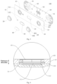
- an inner side surface 102 (the surface, facing to the inside of the battery, of the end cover 10) of the end cover 10 is connected with an insulation board 60 which does not need to vacate overmuch space in correspondence to the anti-explosion valve 51, in this way, the insulation board 60 can provide a greater supporting effect for the end cover 10 to reduce the deformation level after the battery end cover assembly 100 bears a pressure.
- the tolerance pressure which can be borne by the anti-explosion valve 51 is approximately 0.4-0.8 MPa. Therefore, the tensile strength of the anti-explosion valve 51 should not be lower than 90 N/mm 2 , the tolerance pressure which can be borne by the anti-explosion valve 51 is prevented from being far lower than 0.4 MPa, and the situation that the anti-explosion valve 51 is opened due to partial temporary temperature or pressure rise inside the battery is avoided, so that the anti-explosion valve 51 cannot be damaged under reasonable temperature or pressure variation, and the error rate of the anti-explosion valve 51 is reduced.
- the tensile strength of the anti-explosion valve 51 is 90, 95, 100, 103, 108, 112, 116, 121, 128, 130, etc. (unit: N/mm 2 ). Further, optionally, the tensile strength of the anti-explosion valve 51 is 110 N/mm 2 .
- notch grooves 513 in the anti-explosion valve 51 there are one or more notch grooves 513 in the anti-explosion valve 51.
- the plurality of notch grooves 513 can be at least partially connected, or the plurality of notch grooves 513 can be disposed at intervals, which is not limited herein.
- the anti-explosion valve 51 is provided with a C-shaped notch groove 513.
- the anti-explosion valve 51 is provided with two C-shaped notch grooves 513 disposed at intervals.
- each notch groove 513 may also be referred to as a runway shape, and such an anti-explosion valve 51 in Fig. 7 may also be referred to as a double-runway-shaped anti-explosion valve.
- the anti-explosion valve 51 is provided with two C-shaped notch grooves 513 disposed symmetrically, and such an anti-explosion valve 51 may also be referred to as a double-C-shaped anti-explosion valve.
- the minimum thickness of the anti-explosion valve 51 on the position of the notch groove 513 is a first thickness n1
- the thickness of the anti-explosion valve on the position of the preset opening area 511 is n2
- n1 accounts for 15% to 25% of n2.
- the thickness proportions of the anti-explosion valve 51 on the positions of the notch groove 513 and the preset opening area 511 are limited, so that the preset opening area 511 cannot to be too thick while the anti-explosion valve 51 on the position of the notch groove 513 is relatively thin.
- the thickness of the anti-explosion valve 51 on the position of the preset opening area 511 is at least four times as large as the thickness of that on the position of the notch groove 513, when the anti-explosion valve 51 is impacted by the internal pressure or is overhigh in temperature, the pressure can be centralized on the position of the notch groove 513, and the position, where the pressure is centralized on the position of the notch groove 513, of the anti-explosion valve 51 is opened, so that more timely exhaust is achieved, and the working sensitivity of the anti-explosion valve 51 is favorably improved.
- the ratio of n1 to n2 may be 15%, 17%, 20%, 23%, 25%, etc.
- the area of a projection of the notch groove 513 on the end cover 10 is a third area S3, and the third area S3 accounts for 1.0% to 1.5% of the second area S2.
- the second area S2 is the area of a projection of the anti-explosion valve 51 on the end cover 10.
- the projection of the anti-explosion valve 51 on the end cover 10 is of a runway shape, and the area taken up by the runway shape is the second area S2.
- a projection of the notch groove 513 on the end cover 10 is of a C-shaped strip in a dash area in Fig. 6 , and the area of this dash area is the third area S3.
- the projection of the anti-explosion valve 51 on the end cover 10 is of a runway shape, and the area taken up by the runway shape is the second area S2.
- the third area S3 is limited to account for 1.0% to 1.5% of the second area S2, that is, the area taken up on the anti-explosion valve 51 by the thinnest area on the anti-explosion valve 51 is limited.
- the proportion of the third area S3 to the second area S2 cannot be too small, there may be more areas on the position of the notch groove 513 to induce pressure or temperature variation when the internal pressure or temperature of the battery reaches the threshold value, so that the anti-explosion valve can be opened in time for pressure relief, and then, the working sensitivity of the anti-explosion valve 51 can be improved.
- the limitation for the proportion of the third area S3 to the second area S2 does not affect the timely opening of the anti-explosion valve 51 when the internal pressure or temperature of the battery varies, however, the third area S3 is relatively small, which can effectively prevent an external impact force from acting on the notch groove 513 and prevent the anti-explosion valve 51 from being opened when the battery end cover assembly 100 is bumped by accident, and therefore, the working stability of the anti-explosion valve 51 can be improved.
- the end cover 10 When the pressure relief mechanism 50 is located on a geometric center of a figure formed by the outer contour of the end cover 10 and the internal pressure or temperature of the battery is overhigh, the end cover 10 may deform, the geometric center of the end cover 10 is away from the edge of the end cover 10 to generate relatively high deformation, so that the anti-explosion valve 51 can induce deformation variation caused by the variation of the internal pressure in time, and the notch groove 513 in the anti-explosion valve 51 can be rapidly opened for exhaust in time.
- the proportion of the third area S3 to the second area S2 may be 1.0%, 1.1%, 1.2%, 1.3%, 1.4%, 1.5%, etc.
- the notch groove 513 is located in the preset opening area 511.
- the notch groove 513 is located in a predetermined open boundary 512, that is, the notch groove 513 is disposed along the predetermined open boundary 512.
- the predetermined open boundary 512 is a rectangular line
- a rectangular area defined by the predetermined open boundary 512 is the preset opening area 511
- the notch groove 513 is disposed along the rectangular line.
- segments of the notch groove 513 can be partially disposed along the predetermined open boundary 512 and partially located in the preset opening area 511. Therefore, the shape of the notch groove 513 is flexibly set.
- the notch groove 513 includes two first notch segments 5131 oppositely disposed and arc-shaped, a linear second notch segment 5132 and two third notch segments 5133 disposed at intervals and linear, wherein the second notch segment 5132 is disposed in parallel to the third notch segments 5133, two ends of the second notch segment 5132 are respectively connected to the two first notch segments 5131, and each of the third notch segments 5133 is connected to the corresponding first notch segment 5131.
- the second notch segment 5132 is connected to one end of each of the two first notch segments 5131, the other end of each of the two first notch segments 5131 is connected to one of the third notch segments 5133, and the two third notch segments 5133 are disposed at intervals.
- the part located between the two third notch segments 5133 is the connecting line 5121, and the outer edges of orthographic projections of the connecting line 5121 and the notch groove 513 jointly form the predetermined open boundary 512.
- the preset opening area 511 can be kept connected on the part on the connecting line 5121, so that the situation that the preset opening area 511 is completely separated from the remaining parts after being opened is avoided.
- the preset opening area 511 may be adhered with electrolyte, etc. and even catches fire in case that an accident occurs; and by connecting the preset opening area 511 to the end cover 10, the burning preset opening area 511 is prevented from being ejected out, and the probability that the fire spreads outwards is reduced.
- the anti-explosion valve 51 is provided with a notch groove 513.
- the minimum thickness of the anti-explosion valve 51 on the position of the notch groove 513 is a first thickness n1 which is 0.04-0.06 mm.
- the anti-explosion valve 51 can be limited to have an appropriate tolerance pressure value and can be opened for exhaust in time when the internal temperature or pressure of the battery is overhigh.
- the range of a radius r1 of a circular arc line is limited, which is beneficial to the uniform distribution of internal stresses of the anti-explosion valve 51 on the wall surface of the notch groove 513 along the circular arc line, and greatly reduces a difference of the internal stresses on all positions of the circular arc line.
- the anti-explosion valve 51 is opened in the notch groove 513 due to deformation.
- the fracture of the anti-explosion valve 51 in the notch groove 513 is mainly caused by bearing the variation of the internal temperature and pressure, the influences from the centralized internal stresses are reduced, and thus, an actual tolerance pressure value of the anti-explosion valve 51 is more accurate.
- the notch groove 513 is generally formed in a cutting or stamping way.
- the contour line on the section, perpendicular to the extension direction of the notch groove 513, of the notch groove 513 is U-shaped or C-shaped, the design of the sharp corner is avoided, the situation that too many burrs are generated by the sharp corner during machining is avoided, the probability that the sharp corner is torn off by pulling and dragging the burrs during production is avoided, and thus, a tolerance pressure value of the anti-explosion valve 51 is prevented from being reduced.
- the contour line on a section of the notch groove (513), perpendicular to the extension direction of the notch groove (513), includes a circular arc line of which the radius r1 is 0.05-0.15 mm.
- the radius r1 of the circular arc line is limited to be at least 0.05 mm, therefore, on one hand, it is easy to machine the circular arc contour, and on the other hand, centralized stresses generated here are effectively reduced.
- the radius r1 of the circular arc line is limited to be not greater than 0.15 mm, so that the depth of the notch groove 513 and the minimum thickness of the anti-explosion valve 51 on the position of the notch groove 513 can be reasonably distributed.
- the radius r1 of the circular arc line may be 0.05, 0.07, 0.09, 0.10, 0.12, 0.13, 0.15 mm, etc.
- the minimum thickness of the anti-explosion valve 51 on the position of the notch groove 513 is a first thickness n1 which is 0.04-0.06 mm.
- the contour line on the section, perpendicular to the extension direction of the notch groove 513, of the notch groove 513 includes the circular arc line of which the radius r1 is 0.05-0.15 mm, which is beneficial to the implementation that the exhaust pressure of the anti-explosion valve 51 reaches an exhaust pressure or temperature threshold value required by the battery.
- the anti-explosion valve 51 is relatively flexible in disposing way, for example, the anti-explosion valve 51 can be integrally formed on the end cover 10.
- the notch groove 513 is stamped in the end cover 10 to facilitate pressure relief of the end cover 10 here, and thus, the anti-explosion valve 51 is formed.
- the battery end cover assembly 100 has a small number of parts, so that the production efficiency is higher.
- the battery end cover assembly 100 further includes an anti-explosion patch 40 attached to an outer side surface of the end cover 10 and covering the pressure relief mechanism 50.
- the liquid injection hole 111 is located between one of the terminal assemblies 20 and the pressure relief mechanism 50.
- the position of the liquid injection hole 111 cannot be excessively deviated, and it is convenient to rapidly disperse the electrolyte to flow during liquid injection.
- the minimum distance between the liquid injection hole 111 and the pressure relief mechanism 50 is b3, the minimum distance between the liquid injection hole 111 and each of the terminal assemblies 20 is b4, and 1.5 ⁇ b3/b4 ⁇ 2.
- the end cover 10 on the position of the liquid injection hole 111 is relatively weak in structure; and by disposing the liquid injection hole 111 to be closer to the terminal assembly 20 and farther from the pressure relief mechanism 50, on one hand, the situation that the liquid injection hole 111 is disposed to be too close to make the end cover 10 easy to deform here is avoided, on the other hand, the liquid injection hole 111 is protected to a certain extent by virtue of the structural strength of the terminal assembly 20, the deformation of the end cover 10 on the position of the liquid injection hole 111 when the end cover 10 is impacted by a pressure is reduced, and thus, the overall structural strength is improved.
- a battery end cover assembly 100 includes an end cover 10, terminal assemblies 20 and a pressure relief mechanism 50, the terminal assemblies 20 and the pressure relief mechanism 50 are both disposed on the end cover 10, and the end cover 10 is provided with a liquid injection structure 11.
- the terminal assemblies 20, the liquid injection structure 11 and the pressure relief structure 50 are disposed at intervals in the length direction of the end cover 10, a figured formed by an outer contour of the end cover 10 has a width median line L1, and the terminal assemblies 20 and the pressure relief structure 50 are both disposed at intervals on the width median line L1.
- connection positions of the both are disposed in the center of the end cover 10 and are not excessively protruded to edges, which is beneficial to the protection for the connection reliability of connections.
- the pressure relief mechanism 50 is further disposed on the width median line L1. Resistance borne when the pressure relief mechanism 50 relieves a pressure to two sides is approximately balanced, which is beneficial to smoother pressure relief.
- a battery end cover assembly 100 includes an end cover 10, terminal assemblies 20, a pressure relief mechanism 50 and an insulation board 60, and the terminal assemblies 20 and the pressure relief mechanism 50 are both disposed on the end cover 10.
- the end cover 10 is provided with an outer side surface 101 and an inner side surface 102 which are opposite in the thickness direction thereof, and the insulation board 60 is connected to the inner side surface 102 of the end cover 10.
- the inner side surface 102 of the end cover 10 refers to a surface, facing the inside of a battery, of the end cover 10. That is, the battery end cover assembly 100 is internally provided with electrode assemblies 300, and the inner side surface 102 of the end cover 10 is disposed to face the electrode assemblies 300.
- the insulation board 60 is a component for separating the end cover 10 from the electrode assemblies 300 and is disposed on the side, facing the electrode assemblies 300, of the end cover 10, and the end cover 10 is insulated and isolated from the electrode assemblies 300 by the insulation board 60.
- the insulation board 60 is made of an insulating material and may be made of a material such as plastics and rubber. Moreover, after the battery end cover assembly 100 includes the insulation board 60, the end cover 10 is supported by the insulation board 60 so as to be improved in overall structural strength and not easy to deform and damage.
- the insulation board 60 is provided with first avoidance holes 61 corresponding to the terminal assemblies 20 and a second avoidance hole 62 corresponding to the pressure relief mechanism 50. Therefore, the first avoidance holes 61 can facilitate electric connection between the terminal assemblies 20 and the electrode assemblies 300 therein, and the second avoidance hole 62 facilitates the impact of a gas to the pressure relief mechanism 50 via the second avoidance hole 62 during exhaust inside the battery.
- the end cover 10 is provided with a liquid injection hole 111 penetrating in the thickness direction thereof.
- the battery end cover assembly 100 further includes a sealing nail 112 connected to the end cover 10 and covering the liquid injection hole 111, and the insulation board 60 is provided with a third avoidance hole 63 corresponding to the liquid injection hole 111, which aims at ensuring that an electrolyte can smoothly enter from the liquid injection hole 111 during liquid injection and flow to the electrode assemblies 300 via the third avoidance hole 63.
- the electrolyte flows more smoothly, and thus, the liquid injection efficiency can be increased.
- the flow direction of the electrolyte can also be guided.
- a battery end cover assembly 100 includes an end cover 10, terminal assemblies 20 and a pressure relief mechanism 50, and the terminal assemblies 20 and the pressure relief mechanism 50 are both disposed on the end cover 10.
- each of the terminal assemblies 20 may include an electrode terminal 204 and a connecting piece 205, the connecting piece 205 is a component for fixing the electrode terminal 204 to the end cover 10, and the electrode terminal 204 is a component for outputting electric energy of a battery.
- the two terminal assemblies 20 are provided and are respectively a positive terminal assembly 21 and a negative terminal assembly 22, and the pressure relief mechanism 50 is located between the two terminal assemblies 20. Therefore, positive and negative electrode connection with other external components (such as a converging member) can be performed on the battery end cover assembly 100, positive and negative electrodes are centralized on the battery end cover assembly 100, so that the integration level is high, and the overall wiring and layout of the battery are more compact, which is beneficial to the reduction of the overall volume.
- other external components such as a converging member
- the distance between axes of the two terminal assemblies 20 is D1
- the minimum distance between the axis of the negative terminal assembly 22 and an outer contour of the end cover 10 is D2
- 5 ⁇ D1/D2 ⁇ 7 the two terminal assemblies 20 can be reasonably distributed in the length direction of the end cover 10, and the structural strength of the end cover 10 in a central area in the length direction can be improved, so that the deformation of the end cover 10 in the center is reduced, and the appearance and performance of the battery are improved.
- a battery end cover assembly 100 includes an end cover 10, terminal assemblies 20 and a pressure relief mechanism 50, and the terminal assemblies 20 and the pressure relief mechanism 50 are both disposed on the end cover 10.
- the terminal assemblies 20 are used for internal and external electric energy transmission of a battery
- the pressure relief mechanism 50 is a component for relieving an internal pressure of the battery.
- the pressure relief mechanism 50 and the terminal assemblies 20 are distributed at intervals in the length direction of the end cover 10.
- the area of a figure formed by an outer contour of the end cover 10 is a first area S1
- the area of a projection of the pressure relief mechanism 50 on the end cover 10 is a second area S2
- the second area S2 accounts for 0.5% to 5% of the first area S1.
- the pressure relief mechanism 50 and the terminal assemblies 20 are distributed at intervals in the length direction of the end cover 10.
- the size of the pressure relief mechanism 50 in the length direction of the end cover 10 is b1 which is referred to as the length of the pressure relief mechanism 50
- the length b1 of the pressure relief mechanism 50 accounts for 5% to 12% of the length b0 of the end cover 10.
- the size of the pressure relief mechanism 50 in the width direction of the end cover 10 is e1 which is referred to as the width of the pressure relief mechanism 50, and the width e1 of the pressure relief mechanism 50 accounts for 15% to 25% of the width e0 of the end cover 10. Therefore, the pressure relief mechanism 50 can take up an area large enough for pressure relief and exhaust, thereby guaranteeing smooth and timely exhaust.
- each side, located on the pressure relief mechanism 50, of the end cover 10 does not have to be set to be too narrow, so that the risk that the edge of the end cover 10 is easily fractured due to the overlarge length and width of the pressure relief mechanism 50 is avoided, and the situation that the end cover 10 is bent and fractured when bearing an impact and a pressure is avoided. Moreover, there is a sufficient space for arranging components on the end cover 10 so that all the components can be spaced without mutual interference.
- the structural strength of the end cover 10 can be guaranteed, excessive deformation caused when the end cover 10 bears a pressure is avoided, the probability that a gas is exhausted from the edge of the end cover 10 when the internal temperature or pressure of the battery is overhigh is avoided, it is ensured that the gas is only exhausted from the pressure relief mechanism 50, the exhaust direction of the gas in the battery can be effectively controlled, it is convenient to perform subsequent treatment on exhausted electrolyte or high-temperature gas, and unwanted corrosion, fire hazards, etc. caused by arbitrary emission of the electrolyte or high-temperature gas in the battery are avoided.
- the proportion of the second area S2 to the first area S1 may be 0.8%, 1.0%, 1.2%, 1.3%, 1.5%, 1.7%, 2.1%, 2.3%, 2.5%, 2.8%, 3.0%, 3.4%, 3.7%, 3.9%, 4.1%, 4.3%, 4.5%, 4.8% and 5.0%.
- the proportion of the length b1 of the pressure relief mechanism 50 to the length b0 of the end cover 10 is 5%, 7%, 9%, 10%, 11.5%, 12%, etc.
- the proportion of the width e1 of the pressure relief mechanism 50 to the width e0 of the end cover 10 is 15%, 17%, 19%, 20%, 21.5%, 22.4%, 23.7%, 24.8%, 25%, etc.
- the pressure relief mechanism 50 is located on a geometric center of a figure formed by an outer contour of the end cover 10.
- the end cover 10 is of a rectangle, and the pressure relief mechanism 50 is located on the intersection point of diagonal lines of the rectangle.
- the distance from the pressure relief mechanism 50 to each position of the edge of the end cover 10 is relatively balanced, and an exhaust path from the inside of the battery to the pressure relief mechanism 50 is relatively short as a whole, which is beneficial to the improvement of a pressure relief effect, so that the situation of untimely pressure relief caused by an overlong distance between a partial position inside the battery and the pressure relief mechanism 50 is avoided, and the probability of partial explosion caused by untimely pressure relief is reduced.
- the pressure relief mechanism 50 is not disposed in the center of the end cover 10, at the moment, the distance between the pressure relief mechanism 50 and the edge of the end cover 10 is also required to be reasonably set.
- the size of the pressure relief mechanism 50 in the length direction of the end cover 10 is b1, the minimum distance between the pressure relief mechanism 50 and each of the terminal assemblies 20 is b2, and b2>b1.
- the terminal assemblies 20 and other external components connected to the terminal assemblies 20 can be spaced from the pressure relief mechanism 50 by a sufficient distance.
- the pressure relief mechanism 50 is not easily blocked by the other external components, the probability that the internal gas and the electrolyte are ejected on the terminal assemblies 20 and the other external components when the pressure relief mechanism 50 performs pressure relief can be reduced, and the probability that the other external components catch fire is reduced.
- the pressure relief mechanism 50 is spaced from the terminal assemblies 20 for a safe distance, the risk of short circuit caused by conducting the positive and negative electrodes of the battery by an ejected material from the pressure relief mechanism 50 is not easily caused, and therefore, the safety of the battery can be improved.
- the terminal assemblies 20 are closer to the edge of the end cover 10 with respect to the pressure relief mechanism 50. As the edge of the end cover 10 is supported, the structural strength on the positions of the terminal assemblies 20 can be improved by virtue of the support borne by the edge of the end cover 10, pressures borne on the terminal assemblies 20 when the battery end cover assembly 100 bears a pressure can be reduced, and the probability that the terminal assemblies 20 are damaged to fall off can be reduced.
- b1/b2 may be 25%, 27.1%, 29.6%, 31.2%, 33.1%, 34.5%, 35%, etc.
- the pressure relief mechanism 50 includes an anti-explosion valve 51, and the anti-explosion valve 51 includes a preset opening area 511.
- the preset opening area 511 is an area reserved for pressure relief when the anti-explosion valve 51 is designed. If pressure relief is required when the internal temperature or pressure of the battery is increased, the preset opening area 511 is opened, so that a pressure relief opening is formed in the anti-explosion valve 51, and the gas in the battery is exhausted from the pressure relief opening formed after the preset opening area 511 is opened.
- the outer edge of the preset opening area 511 is referred to as a predetermined open boundary 512.
- the predetermined open boundary 512 is an edge contour of the pressure relief opening formed after the preset opening area 511 is opened.
- the anti-explosion valve 51 is provided with a notch groove 513, and the anti-explosion valve 51 on the position of the notch groove 513 is the thinnest, which is beneficial to the timely pressure relief and exhaust.
- the preset opening area 511 can also be set to be of a thin wall as a whole, and any part of the thin wall can be torn off when being impacted by a pressure.
- the notch groove 513 is located in the preset opening area 511.
- the notch groove 513 is located in a predetermined open boundary 512, that is, the notch groove 513 is disposed along the predetermined open boundary 512.
- the predetermined open boundary 512 is a rectangular line
- a rectangular area defined by the predetermined open boundary 512 is the preset opening area 511
- the notch groove 513 is disposed along the rectangular line.
- the notch groove 513 does not have to be disposed along the predetermined open boundary 512.
- the predetermined open boundary 512 is the rectangular line
- the rectangular area defined by the predetermined open boundary 512 is the preset opening area 511
- the notch groove 513 is disposed along diagonal lines of the preset opening area 511.
- the preset opening area 511 can be torn off along the diagonal lines to form four triangular areas. After the preset opening area 511 is opened, the formed pressure relief opening is rectangular.
- the minimum thickness of the anti-explosion valve 51 on the position of the notch groove 513 is a first thickness n1
- the thickness of the anti-explosion valve on the position of the preset opening area 511 is n2
- n1 accounts for 15% to 25% of n2.
- the thickness proportions of the anti-explosion valve 51 on the positions of the notch groove 513 and the preset opening area 511 are limited, so that the preset opening area 511 cannot to be too thick while the anti-explosion valve 51 on the position of the notch groove 513 is relatively thin.
- the area of a projection of the notch groove 513 on the end cover 10 is a third area S3, and the third area S3 accounts for 1.0% to 1.5% of the second area S2.
- the second area S2 is the area of a projection of the anti-explosion valve 51 on the end cover 10.
- the third area S3 is limited to account for 1.0% to 1.5% of the second area S2, that is, the area taken up on the anti-explosion valve 51 by the thinnest area on the anti-explosion valve 51 is limited.
- the proportion of the third area S3 to the second area S2 cannot be too small, there may be more areas on the position of the notch groove 513 to induce pressure or temperature variation when the internal pressure or temperature of the battery reaches the threshold value, so that the anti-explosion valve can be opened in time for pressure relief, and then, the working sensitivity of the anti-explosion valve 51 can be improved.
- the proportion of the third area S3 to the second area S2 may be 1.0%, 1.1%, 1.2%, 1.3%, 1.4%, 1.5%, etc.
- the tensile strength of the anti-explosion valve 51 is 90-130 N/mm 2 , in this way, the situation that the anti-explosion valve 51 is opened when the internal pressure or temperature does not reach a threshold value due to instable performance caused by overlow tensile strength is avoided, and the situation that untimely exhaust caused by difficulty in opening the anti-explosion valve 51 due to overhigh tensile strength is also avoided. Therefore, the reasonable setting of the tensile strength of the anti-explosion valve 51 is beneficial to the improvement of the performance playing reliability and stability.
- the tensile strength of the anti-explosion valve 51 should not be more than 130 N/mm 2 , and the tolerance pressure which can be borne by the anti-explosion valve 51 is prevented from being far more than 0.8 MPa, so that the situation that the anti-explosion valve 51 is still not opened when there is an explosion rise inside the battery is avoided, and it is ensured that the anti-explosion valve 51 can be opened in time for exhaust.
- An appropriate tensile strength is selected for the anti-explosion valve 51, so that the anti-explosion valve 51 is not easily damaged during machining and assembling, and the production defect rate of the battery end cover assembly is reduced.
- the tensile strength of the anti-explosion valve 51 is 90, 95, 100, 103, 108, 112, 116, 121, 128, 130, etc. (unit: N/mm 2 ). Further, optionally, the tensile strength of the anti-explosion valve 51 is 110 N/mm 2 .
- a section, perpendicular to the extension direction of the notch groove 513, of the notch groove 513 is U-shaped or C-shaped.
- the contour line on the section, perpendicular to the extension direction of the notch groove 513, of the notch groove 513 includes a circular arc line of which the radius r1 is 0.05-0.15 mm.
- the radius r1 of the circular arc line is limited to be at least 0.05 mm, therefore, on one hand, it is easy to machine the circular arc contour, and on the other hand, centralized stresses generated here are effectively reduced.
- the radius r1 of the circular arc line is limited to be not greater than 0.15 mm, so that the depth of the notch groove 513 and the minimum thickness of the anti-explosion valve 51 on the position of the notch groove 513 can be reasonably distributed.
- the radius r1 of the circular arc line may be 0.05, 0.07, 0.09, 0.10, 0.12, 0.13, 0.15 mm, etc.
- the end cover 10 is provided with a liquid injection hole 111 penetrating in the thickness direction thereof.
- the battery end cover assembly 100 further includes a sealing nail 112 connected to the end cover 10 and covering the liquid injection hole 111.
- the minimum distance between the liquid injection hole 111 and the pressure relief mechanism 50 is b3, the minimum distance between the liquid injection hole 111 and each of the terminal assemblies 20 is b4, and 1.5 ⁇ b3/b4 ⁇ 2.
- the end cover 10 on the position of the liquid injection hole 111 is relatively weak in structure; and by disposing the liquid injection hole 111 to be closer to the terminal assembly 20 and farther from the pressure relief mechanism 50, on one hand, the situation that the liquid injection hole 111 is disposed to be too close to make the end cover 10 easy to deform here is avoided, on the other hand, the liquid injection hole 111 is protected to a certain extent by virtue of the structural strength of the terminal assembly 20, the deformation of the end cover 10 on the position of the liquid injection hole 111 when the end cover 10 is impacted by a pressure is reduced, and thus, the overall structural strength is improved.
- An energy storage apparatus 01A includes the battery end cover assembly 100 according to the above-mentioned embodiment.
- the battery end cover assembly 100 by obtaining the battery end cover assembly 100 of which the area is matched with the pressure relief capacity, the smoothness of the anti-explosion pressure relief is guaranteed, meanwhile, the structural strength of the battery end cover assembly 100 is guaranteed, and thus, the use safety of the energy storage apparatus 01A is improved.
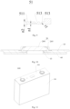
- the energy storage apparatus 01A is a single battery 1000 as shown in Fig. 11 and Fig. 12 .
- a battery module 1000B is shown in Fig. 13 and a battery pack 1000C is shown in Fig. 14 .
- the single battery 1000 includes a housing 200, electrode assemblies 300 and a battery end cover assembly 100, the housing 200 is provided with an opening 200a, the electrode assemblies 300 are accommodated in the housing 200, an end cover 10 of the battery end cover assembly 100 covers the opening 200a, and an inner side surface 102 of the end cover 10 is disposed to face the electrode assemblies 300.
- the housing 200 is a component for accommodating the electrode assemblies 300, and the housing 200 may be of a hollow structure formed with an opening 200a in one end or a hollow structure formed with openings 200a in two ends.
- the housing 200 may be of various shapes such as a cylinder and a cuboid.
- the housing 200 may be made of various materials such as copper, iron, aluminum, steel and aluminum alloy.
- Electrodes assemblies 300 there may be one or more electrode assemblies 300 in the housing 200.
- the battery end cover assembly 100 is an assembly covering the opening 200a of the housing 200 to insulate the internal environment of the single battery 1000 from the external environment.
- the battery end cover assembly 100 includes an end cover 10, terminal assemblies 20 and a pressure relief mechanism 50, and the terminal assemblies 20 and the pressure relief mechanism 50 are both disposed on the end cover 10.
- the area of a figure formed by an outer contour of the end cover 10 is a first area S1
- the area of a projection of the pressure relief mechanism 50 on the end cover 10 is a second area S2
- the second area S2 accounts for 0.5% to 5% of the first area S1.
- the single battery 1000 adopts the above-mentioned battery end cover assembly 100, the area taken up by the pressure relief mechanism 50 on the end cover 10 is reasonably set, and there is a pressure relief opening large enough for exhaust after the pressure relief mechanism 50 is opened, so that the area of the end of the single battery 1000 is relatively matched with the pressure relief capacity. In this way, the probability of untimely pressure relief is reduced, and the safety of the single battery 1000 is improved. Moreover, the overall structural strength of the battery end cover assembly 100 can be guaranteed, and the battery end cover assembly is not easy to deform after bearing a pressure, so that the reliability of the overall single battery 1000 can be improved.
- the single battery 1000 may include a lithium ion secondary battery, a lithium ion primary battery, a lithium-sulfur battery, a sodium-lithium ion battery, a sodium ion battery or a magnesium ion battery, etc., which is not limited in the embodiment of the present application.
- the single battery 1000 may be cylindrical, flat, cuboid or in other shapes, which is not limited in the embodiment of the present application.
- the single battery 1000 is generally divided into three types: a single cylinder battery, a single prismatic battery and a single pouch battery according to a packaging way, which is not limited either in the embodiment of the present application.
- the housing 200 is internally provided with the electrode assemblies 300 and an electrolyte, and each of the electrode assemblies 300 is composed of a positive pole piece, a negative pole piece and an isolating membrane.
- the single battery 1000 mainly works by virtue of the movement of metal ions between the positive pole piece and the negative pole piece.
- the positive pole piece includes a positive current collector and a positive active material layer, the positive active material layer is coated on the surface of the positive current collector, the positive current collector uncoated with the positive active material layer protrudes out of the positive current collector coated with the positive active material layer, and the positive current collector uncoated with the positive active material layer is used as a positive tab.
- the positive current collector may be made of aluminum, and the positive active material layer may be lithium cobaltate, lithium ion phosphate, ternary lithium or lithium manganate, etc.
- the negative pole piece includes a negative current collector and a negative active material layer, the negative active material layer is coated on the surface of the negative current collector, the negative current collector uncoated with the negative active material layer protrudes out of the negative current collector coated with the negative active material layer, and the negative current collector uncoated with the negative active material layer is used as a negative tab.
- the negative current collector may be made of copper, and the negative active material layer may be carbon or silicon, etc.
- each of the electrode assemblies 300 may be of a wound structure or a laminated structure, and embodiments of the present application are not limited thereto.
- the battery end cover assembly 100 generally includes an end cover 10 and terminal assemblies 20, as shown in Fig. 10 , each of the terminal assemblies 20 includes an electrode terminal 204 and a connecting piece 205, the electrode terminal 204 is fixed to the end cover 10 via the connecting piece 205, and the electrode terminal 204 is used to be electrically connected to the electrode assemblies 300 and is a component for outputting electric energy for the single battery 1000.
- the ratio of the capacity a of the single battery 1000 to the second area S2 is at least equal to 1.8, wherein the unit of the capacity a is ampere ⁇ hour (A ⁇ H), and the unit of the second area S2 is square millimeter (mm 2 ). In this way, the capacity a of the single battery 1000 can be further reasonably matched with the area taken up by the pressure relief mechanism 50.
- the pressure relief opening of the pressure relief mechanism 50 is relatively large, when abnormal conditions such as short circuit, overcharge and overdischarge occur to the single battery 1000, an internal pressure of the single battery 1000 sharply rises, and when the pressure reaches a set anti-explosion air pressure point of the battery, the pressure relief mechanism 50 can be instantly opened to ensure that the gas inside the single battery 1000 can be exhausted in time, prevent the single battery 1000 from being exploded and play a role of instantly and completely leaking the gas, and thus, the anti-explosion purpose is achieved.
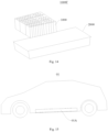
- the battery module 1000B according to an example of the present application, as shown in Fig. 13 , includes a plurality of single batteries 1000 which are arranged according to a certain sequence.
- the battery pack 1000C includes a box body 2000 and a battery module 1000B, and the box body 2000 is used for accommodating at least one battery module 1000B.
- the battery module 1000B is formed by arranging a plurality of single batteries 1000, and therefore, the battery pack 1000C includes the box body 2000 and the plurality of single batteries 1000.
- the box body 2000 is a component for accommodating the single batteries 1000, provides an accommodating space for the single batteries 1000 and may be of various structures.
- the box body 2000 may include a first part and a second part which are covered on each other to define an accommodating space for accommodating the single batteries 1000.
- the first part and the second part may be of various shapes such as a cuboid and a cylinder.
- the first part may be of a hollow structure opened in one side
- the second part may also be of a hollow structure opened in one side
- the open side of the second part covers the open side of the first part to form the box body 2000 with the accommodating space.
- the first part is of a hollow structure opened in one side
- the second part is of a plate-like structure
- the second part covers the open side of the first part to form the box body 2000 with the accommodating space.
- the first part and the second part can be sealed by a sealing element which may be a sealing ring, a sealant, etc.
- the box body 2000 can prevent liquid or other foreign matters from affecting the charge or discharge of the single batteries 1000.
- the battery pack 1000C there may be one or more single batteries 1000. If there are a plurality of single batteries 1000, the plurality of single batteries 1000 are in series connection or parallel connection or parallel-series connection, and the parallel-series connection means that the plurality of single batteries 1000 are both in serial connection and parallel connection. It is possible that the plurality of single batteries 1000 are in series connection or parallel connection or parallel-series connection to form the battery module 1000B firstly, and then, a plurality of battery modules 1000B are in series connection or parallel connection or parallel-series connection to form an integral whole to be accommodated in the box body 2000. Or, all the single batteries 1000 are in direct series connection or parallel connection or parallel-series connection together, and then, the integral whole formed by all the single batteries 1000 is accommodated in the box body 2000.
- the battery pack 1000C may further include a converging member by which the plurality of single batteries 1000 can be electrically connected to achieve the series connection or parallel connection or parallel-series connection among of the plurality of single batteries 1000.
- the converging member may be a metal conductor such as copper, iron, aluminum, stainless steel and aluminum alloy.
- Each of the plurality of single batteries 1000 in the battery pack 1000C adopts the above-mentioned battery end cover assembly 100, and when being leaked during the assembly of the battery pack 1000C, a certain or some single batteries 1000 can be rapidly recognized, so that the overhaul convenience of the battery pack 1000C can be improved.
- the electric device 01 may be a vehicle, a mobile phone, a portable device, a notebook computer, a ship, a spacecraft, an electric toy, an electric tool, etc.
- the vehicle may be a fuel vehicle, a gas vehicle or a new energy vehicle, and the new energy vehicle may be a battery electric vehicle, a hybrid electric vehicle or a range-extended vehicle, etc.
- the spacecraft includes an airplane, a rocket, an aerospace plane, a spaceship, etc.
- the electric toy includes a fixed electric toy or a mobile electric toy, such as a game machine, an electric vehicle toy, an electric ship toy, an electric airplane toy, etc.
- the electric tool includes an electric metal cutting tool, an electric grinding tool, an electric assembling tool and an electric tool for a railway, such as an electric drill, an electric grinder, an electric wrench, an electric screwdriver, an electric hammer, an electric impact drill, a concrete vibrator, an electric planer, etc.
- the electric device 10 which is a vehicle is used as an example to be described in the following embodiment.
- Fig. 15 is a schematic view of a vehicle according to some embodiments of the present application
- the vehicle is internally provided with an energy storage apparatus 01A which may be disposed on the bottom, head or tail of the vehicle.
- the energy storage apparatus 01A may be used for supplying power for the vehicle, for example, the energy storage apparatus 01A may be used as an operational power supply for the vehicle.
- the electric device 01 according to an embodiment of the present application adopts the above-mentioned energy storage apparatus 01A, so that the working stability as well as reliability and safety of the electric device 01 can be improved.
- the vehicle may further include a controller and a motor, and the controller is used for controlling the energy storage apparatus 01A to supply power for the motor, for example, it is used for meeting the demands on working power when the vehicle is started, navigated and driven.
- the energy storage apparatus 01A not only can be used as the operational power supply for the vehicle, but also can be used as a driving power supply for the vehicle to replace or partially replace fuel or natural gas to supply a driving force to the vehicle.
- the electric device 01 may also be an energy storage device such as an energy storage cabinet, and may be used as a charging cabinet for a mobile device or an energy storage device for other devices.
- a solar power generation device may be configured with an energy storage cabinet, electric energy generated by solar power generation is temporarily stored in the energy storage cabinet so as to be utilized by an apparatus such as a sheet lamp and a bus stop board.
Landscapes
- Chemical & Material Sciences (AREA)
- Chemical Kinetics & Catalysis (AREA)
- Electrochemistry (AREA)
- General Chemical & Material Sciences (AREA)
- Gas Exhaust Devices For Batteries (AREA)
- Battery Mounting, Suspending (AREA)
- Connection Of Batteries Or Terminals (AREA)
Claims (10)
- Energiespeichervorrichtung (01A), wobei die Energiespeichervorrichtung (01A) eine einzelne Batterie (1000) ist, umfassend eine Batterieendabdeckungsanordnung (100), wobei die Batterieendabdeckungsanordnung (100) umfasst:eine rechteckige Endabdeckung (10);Anschlussanordnungen (20), wobei die Anschlussanordnungen (20) mit der Endabdeckung (10) verbunden sind; undeinen Druckentlastungsmechanismus (50), wobei der Druckentlastungsmechanismus (50) an der Endabdeckung (10) angeordnet ist, und wobei der Druckentlastungsmechanismus (50) und die Anschlussanordnungen (20) in Abständen in Längsrichtung der Endabdeckung (10) verteilt sind; wobeidie Fläche einer durch eine Außenkontur der Endabdeckung (10) gebildeten Figur eine erste Fläche S1 ist, die Fläche einer Projektion des Druckentlastungsmechanismus (50) auf der Endabdeckung (10) eine zweite Fläche S2 ist, und die zweite Fläche S2 0,5 % bis 5 % der ersten Fläche S1 ausmacht;die Größe des Druckentlastungsmechanismus (50) in Längsrichtung der Endabdeckung (10) b1 ist, und b1 5 % bis 12 % der Länge b0 der Endabdeckung (10) ausmacht; unddie Größe des Druckentlastungsmechanismus (50) in Breitenrichtung der Endabdeckung (10) e1 ist, und e1 15% bis 25% der Breite e0 der Endabdeckung (10) ausmacht;der Druckentlastungsmechanismus (50) ein Explosionsschutzventil (51) umfasst, und das Explosionsschutzventil (51) einen voreingestellten Öffnungsbereich (511) umfasst;das Explosionsschutzventil (51) mit einer Kerbennut (513) versehen ist und sich die Kerbennut (513) in dem voreingestellten Öffnungsbereich (511) befindet;die Mindestdicke des Explosionsschutzventils (51) an der Position der Kerbnut (513) eine erste Dicke n1 ist, die Dicke des Explosionsschutzventils (51) an der Position des voreingestellten Öffnungsbereichs (511) eine zweite Dicke n2 ist, und die erste Dicke n1 15 % bis 25 % der zweiten Dicke n2 ausmacht;die Zugfestigkeit des Explosionsschutzventils (51) 90 - 130 N/mm2 beträgt;eine Fläche des voreingestellten Öffnungsbereichs (511) mindestens die Hälfte der zweiten Fläche S2 und nicht mehr als 95 % der zweiten Fläche S2 beträgt; undein Verhältnis (a/S2) einer Kapazität a der Energiespeichervorrichtung (01A) zu der zweiten Fläche (S2) mindestens gleich 1,8 ist, wobei die Einheit der Kapazität a die Amperestunde (AH) ist, und wobei die Einheit der zweiten Fläche S2 mm2 ist.
- Energiespeichervorrichtung (01A) nach Anspruch 1, wobei die Fläche eines Vorsprungs der Kerbennut (513) auf der Endabdeckung (10) eine dritte Fläche S3 ist, und wobei die dritte Fläche S3 1,0 % bis 1,5 % der zweiten Fläche S2 ausmacht.
- Energiespeichervorrichtung (01A) nach Anspruch 1, wobei eine Konturlinie auf einem Abschnitt der Kerbennut (513), senkrecht zur Erstreckungsrichtung der Kerbennut (513), eine C-Form oder eine U-Form aufweist.
- Energiespeichervorrichtung (01A) nach Anspruch 1, wobei eine Konturlinie auf einem Abschnitt der Kerbennut (513), senkrecht zur Erstreckungsrichtung der Kerbennut (513), eine Kreisbogenlinie umfasst, deren Radius r1 0,05 bis 0,15 mm beträgt.
- Energiespeichervorrichtung (01A) nach Anspruch 1, wobei der Mindestabstand zwischen dem Druckentlastungsmechanismus (50) und jeder der Anschlussanordnungen (20) b2 ist, und b2>b1.
- Energiespeichervorrichtung (01A) nach Anspruch 5, wobei 25%≤b1/b2≤35%.
- Energiespeichervorrichtung (01A) nach Anspruch 1, wobei der Druckentlastungsmechanismus (50) auf einem geometrischen Mittelpunkt einer durch die Außenkontur der Endabdeckung (10) gebildeten Figur angeordnet ist.
- Energiespeichervorrichtung (01A) nach einem der Ansprüche 1 bis 7, wobei die Endabdeckung (10) mit einem in Richtung ihrer Dicke durchgehenden Flüssigkeitseinspritzloch (111) versehen ist, und wobei das Flüssigkeitseinspritzloch (111) zwischen einer der Anschlussanordnungen (20) und dem Druckentlastungsmechanismus (50) angeordnet ist;
wobei der Mindestabstand zwischen dem Flüssigkeitseinspritzloch (111) und dem Druckentlastungsmechanismus (50) b3 ist, der Mindestabstand zwischen dem Flüssigkeitseinspritzloch (111) und einer der Anschlussanordnungen (20) b4 ist, und 1,5≤b3/b4≤2. - Energiespeichervorrichtung (01A) nach einem der Ansprüche 1 bis 7, wobei zwei Anschlussanordnungen (20) jeweils als eine positive Anschlussanordnung (21) und eine negative Anschlussanordnung (22) vorgesehen sind, wobei der Druckentlastungsmechanismus (50) zwischen den beiden Anschlussanordnungen (20) angeordnet ist, wobei der Abstand zwischen den Achsen der beiden Anschlussanordnungen (20) D1 ist, wobei der Mindestabstand zwischen der Achse der negativen Anschlussanordnung (22) und der Außenkontur der Endabdeckung (10) D2 ist, 5≤D1/D2≤7.
- Elektrisches Gerät (01), das die Energiespeichervorrichtung (01A) nach einem der Ansprüche 1 bis 9 umfasst.
Applications Claiming Priority (1)
| Application Number | Priority Date | Filing Date | Title |
|---|---|---|---|
| CN202211412919.2A CN115472997B (zh) | 2022-11-11 | 2022-11-11 | 电池端盖组件、储能装置以及用电设备 |
Publications (2)
| Publication Number | Publication Date |
|---|---|
| EP4401206A1 EP4401206A1 (de) | 2024-07-17 |
| EP4401206B1 true EP4401206B1 (de) | 2025-06-25 |
Family
ID=84338150
Family Applications (1)
| Application Number | Title | Priority Date | Filing Date |
|---|---|---|---|
| EP23208852.6A Active EP4401206B1 (de) | 2022-11-11 | 2023-11-09 | Energiespeichervorrichtung mit batterieendabdeckungsanordnung, und elektrische vorrichtung |
Country Status (6)
| Country | Link |
|---|---|
| US (1) | US11909066B1 (de) |
| EP (1) | EP4401206B1 (de) |
| CN (1) | CN115472997B (de) |
| DE (1) | DE202023100807U1 (de) |
| ES (1) | ES3039456T3 (de) |
| HU (1) | HUE072572T2 (de) |
Families Citing this family (25)
| Publication number | Priority date | Publication date | Assignee | Title |
|---|---|---|---|---|
| KR102945400B1 (ko) | 2022-04-19 | 2026-03-27 | 샤먼 홍파 일렉트릭 파워 컨트롤즈 컴퍼니 리미티드 | 릴레이 |
| CN118213681A (zh) * | 2022-12-16 | 2024-06-18 | 厦门海辰储能科技股份有限公司 | 一种端盖组件、电池、电池包及用电设备 |
| JP2025526800A (ja) * | 2023-01-13 | 2025-08-15 | 香港時代新能源科技有限公司 | 電池セル、電池および電気機器 |
| CN116259919A (zh) * | 2023-05-08 | 2023-06-13 | 江苏正力新能电池技术有限公司 | 一种电池、模组和用电设备 |
| CN116454358B (zh) * | 2023-06-16 | 2023-08-15 | 深圳海辰储能控制技术有限公司 | 储能装置及用电设备 |
| CN116613456B (zh) * | 2023-06-28 | 2025-04-11 | 蜂巢能源科技股份有限公司 | 电池的外壳及电池 |
| CN117059979B (zh) * | 2023-10-13 | 2024-01-26 | 厦门海辰储能科技股份有限公司 | 端盖组件、储能装置及用电设备 |
| CN117096543B (zh) * | 2023-10-18 | 2024-02-20 | 蜂巢能源科技股份有限公司 | 一种电池、电池模组和电池包 |
| CN221828076U (zh) * | 2023-10-20 | 2024-10-11 | 宁德时代新能源科技股份有限公司 | 电池单体、电池和用电装置 |
| CN117239345B (zh) * | 2023-11-15 | 2024-04-05 | 宁德新能源科技有限公司 | 电化学装置及用电设备 |
| CN117438655A (zh) * | 2023-12-20 | 2024-01-23 | 宁德时代新能源科技股份有限公司 | 电池单体、电池和用电装置 |
| WO2025138197A1 (zh) * | 2023-12-29 | 2025-07-03 | 惠州亿纬动力电池有限公司 | 电池防爆结构、电池和电池包 |
| CN117525774B (zh) * | 2024-01-08 | 2024-04-09 | 深圳海辰储能科技有限公司 | 储能装置和用电设备 |
| CN118213597A (zh) * | 2024-03-08 | 2024-06-18 | 宁德时代新能源科技股份有限公司 | 电池单体、电池及用电装置 |
| CN117977101B (zh) * | 2024-03-28 | 2024-07-19 | 蜂巢能源科技股份有限公司 | 电池、电池包及用电装置 |
| CN221201353U (zh) * | 2024-04-07 | 2024-06-21 | 宁德时代新能源科技股份有限公司 | 端盖组件、电池单体、电池及用电装置 |
| CN120834371A (zh) * | 2024-04-18 | 2025-10-24 | 比亚迪股份有限公司 | 电池单体的盖板组件、电池单体、电池包及用电装置 |
| CN222507932U (zh) * | 2024-04-30 | 2025-02-18 | 惠州亿纬动力电池有限公司 | 顶盖组件及电池 |
| DE102024117277A1 (de) * | 2024-06-19 | 2025-12-24 | Schaeffler Technologies AG & Co. KG | Verfahren zur Herstellung eines Batteriezellengehäuses mit Überdruckabbaumittel sowie Batteriezellengehäuse und Batteriezelle |
| DE102024117278A1 (de) * | 2024-06-19 | 2025-12-24 | Schaeffler Technologies AG & Co. KG | Batteriezellengehäuse mit einer Berstnut und Sollbruchstelle |
| WO2026011281A1 (en) * | 2024-07-08 | 2026-01-15 | Powerco Se | Housing, battery cell, battery and power-using device |
| CN121331709A (zh) * | 2024-07-12 | 2026-01-13 | 厦门宏发电力电器有限公司 | 继电器 |
| WO2026060667A1 (zh) * | 2024-09-20 | 2026-03-26 | 宁德时代新能源科技股份有限公司 | 电池单体、电池装置及用电装置 |
| WO2026060666A1 (zh) * | 2024-09-20 | 2026-03-26 | 宁德时代新能源科技股份有限公司 | 电池单体、泄压机构、电池及用电设备 |
| CN119779666B (zh) * | 2024-12-31 | 2026-03-17 | 蜂巢能源科技股份有限公司 | 一种电池防爆阀校验方法 |
Family Cites Families (13)
| Publication number | Priority date | Publication date | Assignee | Title |
|---|---|---|---|---|
| JP2009259606A (ja) * | 2008-04-17 | 2009-11-05 | Toyota Motor Corp | 内圧開放弁の製造方法および密閉型電池 |
| JP5129280B2 (ja) * | 2010-02-26 | 2013-01-30 | 日立ビークルエナジー株式会社 | 二次電池 |
| DE112013005296T5 (de) * | 2012-11-06 | 2015-07-16 | Kabushiki Kaisha Toyota Jidoshokki | Leistungsspeichervorrichtung |
| JP5668772B2 (ja) * | 2013-03-25 | 2015-02-12 | 株式会社豊田自動織機 | 蓄電装置 |
| JP6614305B1 (ja) * | 2018-09-21 | 2019-12-04 | 日本軽金属株式会社 | 一体型防爆弁成形用の電池蓋用アルミニウム合金板及びその製造方法 |
| CN212571194U (zh) * | 2020-06-24 | 2021-02-19 | 欣旺达电动汽车电池有限公司 | 二次电池 |
| CN213340640U (zh) * | 2020-11-09 | 2021-06-01 | 宁德时代新能源科技股份有限公司 | 端盖组件、电池单体、电池以及用电装置 |
| JP7403561B2 (ja) * | 2021-03-23 | 2023-12-22 | 寧徳時代新能源科技股▲分▼有限公司 | 電池のケース、電池、電力消費装置、電池製造方法及び装置 |
| CA3166962A1 (en) * | 2021-04-16 | 2022-10-16 | Mingguang GU | Battery cell, battery, power consumption apparatus, method and apparatus for producing battery cell |
| CN216698639U (zh) * | 2021-12-28 | 2022-06-07 | 宁德时代新能源科技股份有限公司 | 端盖组件、电池单体、电池、用电设备及电池单体的制造设备 |
| CN114497876B (zh) * | 2022-04-07 | 2022-07-05 | 中创新航科技股份有限公司 | 电池及电池组 |
| CN216980798U (zh) * | 2022-05-12 | 2022-07-15 | 比亚迪股份有限公司 | 防爆阀、电池、电池模组、电池包以及车辆 |
| CN217334238U (zh) * | 2022-06-14 | 2022-08-30 | 宁德时代新能源科技股份有限公司 | 外壳、电池单体、电池及用电设备 |
-
2022
- 2022-11-11 CN CN202211412919.2A patent/CN115472997B/zh active Active
-
2023
- 2023-02-14 US US18/109,332 patent/US11909066B1/en active Active
- 2023-02-20 DE DE202023100807.0U patent/DE202023100807U1/de active Active
- 2023-11-09 EP EP23208852.6A patent/EP4401206B1/de active Active
- 2023-11-09 ES ES23208852T patent/ES3039456T3/es active Active
- 2023-11-09 HU HUE23208852A patent/HUE072572T2/hu unknown
Also Published As
| Publication number | Publication date |
|---|---|
| EP4401206A1 (de) | 2024-07-17 |
| DE202023100807U1 (de) | 2023-06-13 |
| ES3039456T3 (en) | 2025-10-21 |
| CN115472997A (zh) | 2022-12-13 |
| CN115472997B (zh) | 2023-03-24 |
| US11909066B1 (en) | 2024-02-20 |
| HUE072572T2 (hu) | 2025-11-28 |
Similar Documents
| Publication | Publication Date | Title |
|---|---|---|
| EP4401206B1 (de) | Energiespeichervorrichtung mit batterieendabdeckungsanordnung, und elektrische vorrichtung | |
| EP4439838A1 (de) | Batteriezelle, batterie und elektrische vorrichtung | |
| EP4243178B1 (de) | Endkappe, batteriezelle, batterie und stromverbrauchende vorrichtung | |
| US20240313339A1 (en) | Battery cell, battery and electricity-consuming apparatus | |
| JP2022543185A (ja) | 電池、その関連装置、製造方法及び製造機器 | |
| US20240372207A1 (en) | Box of battery, battery, power consumption apparatus, and method and apparatus for producing battery | |
| US20220013855A1 (en) | Battery box, battery cell, battery, and method and apparatus for preparing battery box | |
| EP4485655A1 (de) | Batterie und elektrische vorrichtung | |
| EP4254622A1 (de) | Batterie, elektrische vorrichtung sowie verfahren und vorrichtung zur herstellung der batterie | |
| US20240313338A1 (en) | Battery cell, method and system for manufacture same, battery, and power consuming device | |
| CN216720146U (zh) | 电池和用电设备 | |
| US20250096381A1 (en) | Battery cell, battery and electrical apparatus | |
| US20230178860A1 (en) | Battery cell, battery, power consuming device, and method and apparatus for manufacturing battery cell | |
| US20240304965A1 (en) | Battery cell, battery, electrical device, and method and equipment for manufacturing battery cell | |
| KR20230035336A (ko) | 케이스, 배터리 셀, 배터리 및 전기 기기 | |
| US20250079651A1 (en) | Battery Cell, Battery and Electrical Equipment | |
| WO2024098401A1 (zh) | 电池端盖组件、储能装置以及用电设备 | |
| US20240421450A1 (en) | Battery cell, battery and electricity-consuming device | |
| EP4391197A1 (de) | Batteriezelle und herstellungsverfahren und herstellungsvorrichtung dafür, batterie und elektrische vorrichtung | |
| CN117044015A (zh) | 电池、用电设备及电池的制备方法和制备装置 | |
| US20250023160A1 (en) | End cover assembly of battery cell, battery cell, battery and electricity-consuming apparatus | |
| US20240413508A1 (en) | Battery cell, battery, electrical device, and method and device for manufacturing battery cell | |
| EP4254610B1 (de) | Batterie und verfahren zu deren herstellung | |
| US20250337082A1 (en) | Battery cell, battery, power consumption device and manufacturing device and method for battery cell | |
| US20250023161A1 (en) | End cover assembly of battery cell, battery cell, battery and electricity-consuming apparatus |
Legal Events
| Date | Code | Title | Description |
|---|---|---|---|
| PUAI | Public reference made under article 153(3) epc to a published international application that has entered the european phase |
Free format text: ORIGINAL CODE: 0009012 |
|
| STAA | Information on the status of an ep patent application or granted ep patent |
Free format text: STATUS: THE APPLICATION HAS BEEN PUBLISHED |
|
| AK | Designated contracting states |
Kind code of ref document: A1 Designated state(s): AL AT BE BG CH CY CZ DE DK EE ES FI FR GB GR HR HU IE IS IT LI LT LU LV MC ME MK MT NL NO PL PT RO RS SE SI SK SM TR |
|
| STAA | Information on the status of an ep patent application or granted ep patent |
Free format text: STATUS: REQUEST FOR EXAMINATION WAS MADE |
|
| 17P | Request for examination filed |
Effective date: 20241106 |
|
| RBV | Designated contracting states (corrected) |
Designated state(s): AL AT BE BG CH CY CZ DE DK EE ES FI FR GB GR HR HU IE IS IT LI LT LU LV MC ME MK MT NL NO PL PT RO RS SE SI SK SM TR |
|
| GRAP | Despatch of communication of intention to grant a patent |
Free format text: ORIGINAL CODE: EPIDOSNIGR1 |
|
| STAA | Information on the status of an ep patent application or granted ep patent |
Free format text: STATUS: GRANT OF PATENT IS INTENDED |
|
| INTG | Intention to grant announced |
Effective date: 20250130 |
|
| RAP3 | Party data changed (applicant data changed or rights of an application transferred) |
Owner name: XIAMEN HITHIUM ENERGY STORAGE TECHNOLOGY CO., LTD. Owner name: SHENZHEN HITHIUM ENERGY STORAGETECHNOLOGY CO., LTD. |
|
| RAP1 | Party data changed (applicant data changed or rights of an application transferred) |
Owner name: HITHIUM TECH HK LIMITED |
|
| GRAS | Grant fee paid |
Free format text: ORIGINAL CODE: EPIDOSNIGR3 |
|
| GRAA | (expected) grant |
Free format text: ORIGINAL CODE: 0009210 |
|
| STAA | Information on the status of an ep patent application or granted ep patent |
Free format text: STATUS: THE PATENT HAS BEEN GRANTED |
|
| AK | Designated contracting states |
Kind code of ref document: B1 Designated state(s): AL AT BE BG CH CY CZ DE DK EE ES FI FR GB GR HR HU IE IS IT LI LT LU LV MC ME MK MT NL NO PL PT RO RS SE SI SK SM TR |
|
| REG | Reference to a national code |
Ref country code: GB Ref legal event code: FG4D |
|
| REG | Reference to a national code |
Ref country code: CH Ref legal event code: EP |
|
| REG | Reference to a national code |
Ref country code: CH Ref legal event code: EP |
|
| REG | Reference to a national code |
Ref country code: IE Ref legal event code: FG4D |
|
| REG | Reference to a national code |
Ref country code: DE Ref legal event code: R096 Ref document number: 602023004299 Country of ref document: DE |
|
| PG25 | Lapsed in a contracting state [announced via postgrant information from national office to epo] |
Ref country code: FI Free format text: LAPSE BECAUSE OF FAILURE TO SUBMIT A TRANSLATION OF THE DESCRIPTION OR TO PAY THE FEE WITHIN THE PRESCRIBED TIME-LIMIT Effective date: 20250625 |
|
| REG | Reference to a national code |
Ref country code: LT Ref legal event code: MG9D |
|
| PG25 | Lapsed in a contracting state [announced via postgrant information from national office to epo] |
Ref country code: GR Free format text: LAPSE BECAUSE OF FAILURE TO SUBMIT A TRANSLATION OF THE DESCRIPTION OR TO PAY THE FEE WITHIN THE PRESCRIBED TIME-LIMIT Effective date: 20250926 Ref country code: NO Free format text: LAPSE BECAUSE OF FAILURE TO SUBMIT A TRANSLATION OF THE DESCRIPTION OR TO PAY THE FEE WITHIN THE PRESCRIBED TIME-LIMIT Effective date: 20250925 |
|
| PG25 | Lapsed in a contracting state [announced via postgrant information from national office to epo] |
Ref country code: HR Free format text: LAPSE BECAUSE OF FAILURE TO SUBMIT A TRANSLATION OF THE DESCRIPTION OR TO PAY THE FEE WITHIN THE PRESCRIBED TIME-LIMIT Effective date: 20250625 |
|
| REG | Reference to a national code |
Ref country code: ES Ref legal event code: FG2A Ref document number: 3039456 Country of ref document: ES Kind code of ref document: T3 Effective date: 20251021 |
|
| PG25 | Lapsed in a contracting state [announced via postgrant information from national office to epo] |
Ref country code: RS Free format text: LAPSE BECAUSE OF FAILURE TO SUBMIT A TRANSLATION OF THE DESCRIPTION OR TO PAY THE FEE WITHIN THE PRESCRIBED TIME-LIMIT Effective date: 20250925 |
|
| PG25 | Lapsed in a contracting state [announced via postgrant information from national office to epo] |
Ref country code: LV Free format text: LAPSE BECAUSE OF FAILURE TO SUBMIT A TRANSLATION OF THE DESCRIPTION OR TO PAY THE FEE WITHIN THE PRESCRIBED TIME-LIMIT Effective date: 20250625 |
|
| REG | Reference to a national code |
Ref country code: NL Ref legal event code: MP Effective date: 20250625 |
|
| PG25 | Lapsed in a contracting state [announced via postgrant information from national office to epo] |
Ref country code: NL Free format text: LAPSE BECAUSE OF FAILURE TO SUBMIT A TRANSLATION OF THE DESCRIPTION OR TO PAY THE FEE WITHIN THE PRESCRIBED TIME-LIMIT Effective date: 20250625 |
|
| REG | Reference to a national code |
Ref country code: HU Ref legal event code: AG4A Ref document number: E072572 Country of ref document: HU |
|
| PG25 | Lapsed in a contracting state [announced via postgrant information from national office to epo] |
Ref country code: PT Free format text: LAPSE BECAUSE OF FAILURE TO SUBMIT A TRANSLATION OF THE DESCRIPTION OR TO PAY THE FEE WITHIN THE PRESCRIBED TIME-LIMIT Effective date: 20251027 |
|
| PGFP | Annual fee paid to national office [announced via postgrant information from national office to epo] |
Ref country code: HU Payment date: 20251107 Year of fee payment: 3 |
|
| REG | Reference to a national code |
Ref country code: AT Ref legal event code: MK05 Ref document number: 1807553 Country of ref document: AT Kind code of ref document: T Effective date: 20250625 |
|
| PG25 | Lapsed in a contracting state [announced via postgrant information from national office to epo] |
Ref country code: IS Free format text: LAPSE BECAUSE OF FAILURE TO SUBMIT A TRANSLATION OF THE DESCRIPTION OR TO PAY THE FEE WITHIN THE PRESCRIBED TIME-LIMIT Effective date: 20251025 |
|
| PGFP | Annual fee paid to national office [announced via postgrant information from national office to epo] |
Ref country code: DE Payment date: 20251124 Year of fee payment: 3 |
|
| PG25 | Lapsed in a contracting state [announced via postgrant information from national office to epo] |
Ref country code: AT Free format text: LAPSE BECAUSE OF FAILURE TO SUBMIT A TRANSLATION OF THE DESCRIPTION OR TO PAY THE FEE WITHIN THE PRESCRIBED TIME-LIMIT Effective date: 20250625 Ref country code: SM Free format text: LAPSE BECAUSE OF FAILURE TO SUBMIT A TRANSLATION OF THE DESCRIPTION OR TO PAY THE FEE WITHIN THE PRESCRIBED TIME-LIMIT Effective date: 20250625 |
|
| P01 | Opt-out of the competence of the unified patent court (upc) registered |
Free format text: CASE NUMBER: UPC_APP_0015277_4401206/2025 Effective date: 20251201 |
|
| PGFP | Annual fee paid to national office [announced via postgrant information from national office to epo] |
Ref country code: FR Payment date: 20251128 Year of fee payment: 3 |
|
| PG25 | Lapsed in a contracting state [announced via postgrant information from national office to epo] |
Ref country code: CZ Free format text: LAPSE BECAUSE OF FAILURE TO SUBMIT A TRANSLATION OF THE DESCRIPTION OR TO PAY THE FEE WITHIN THE PRESCRIBED TIME-LIMIT Effective date: 20250625 |
|
| PG25 | Lapsed in a contracting state [announced via postgrant information from national office to epo] |
Ref country code: PL Free format text: LAPSE BECAUSE OF FAILURE TO SUBMIT A TRANSLATION OF THE DESCRIPTION OR TO PAY THE FEE WITHIN THE PRESCRIBED TIME-LIMIT Effective date: 20250625 |
|
| PGFP | Annual fee paid to national office [announced via postgrant information from national office to epo] |
Ref country code: BG Payment date: 20251119 Year of fee payment: 3 |
|
| PG25 | Lapsed in a contracting state [announced via postgrant information from national office to epo] |
Ref country code: EE Free format text: LAPSE BECAUSE OF FAILURE TO SUBMIT A TRANSLATION OF THE DESCRIPTION OR TO PAY THE FEE WITHIN THE PRESCRIBED TIME-LIMIT Effective date: 20250625 |
|
| PG25 | Lapsed in a contracting state [announced via postgrant information from national office to epo] |
Ref country code: SK Free format text: LAPSE BECAUSE OF FAILURE TO SUBMIT A TRANSLATION OF THE DESCRIPTION OR TO PAY THE FEE WITHIN THE PRESCRIBED TIME-LIMIT Effective date: 20250625 |
|
| PGFP | Annual fee paid to national office [announced via postgrant information from national office to epo] |
Ref country code: ES Payment date: 20251202 Year of fee payment: 3 |
|
| PG25 | Lapsed in a contracting state [announced via postgrant information from national office to epo] |
Ref country code: RO Free format text: LAPSE BECAUSE OF FAILURE TO SUBMIT A TRANSLATION OF THE DESCRIPTION OR TO PAY THE FEE WITHIN THE PRESCRIBED TIME-LIMIT Effective date: 20250625 |
|
| PG25 | Lapsed in a contracting state [announced via postgrant information from national office to epo] |
Ref country code: DK Free format text: LAPSE BECAUSE OF FAILURE TO SUBMIT A TRANSLATION OF THE DESCRIPTION OR TO PAY THE FEE WITHIN THE PRESCRIBED TIME-LIMIT Effective date: 20250625 |
|
| PG25 | Lapsed in a contracting state [announced via postgrant information from national office to epo] |
Ref country code: IT Free format text: LAPSE BECAUSE OF FAILURE TO SUBMIT A TRANSLATION OF THE DESCRIPTION OR TO PAY THE FEE WITHIN THE PRESCRIBED TIME-LIMIT Effective date: 20250625 |