EP4401265A1 - Fonctionnement optimisé d'une installation d'électrolyse et d'un accumulateur d'énergie électrique - Google Patents
Fonctionnement optimisé d'une installation d'électrolyse et d'un accumulateur d'énergie électrique Download PDFInfo
- Publication number
- EP4401265A1 EP4401265A1 EP23151358.1A EP23151358A EP4401265A1 EP 4401265 A1 EP4401265 A1 EP 4401265A1 EP 23151358 A EP23151358 A EP 23151358A EP 4401265 A1 EP4401265 A1 EP 4401265A1
- Authority
- EP
- European Patent Office
- Prior art keywords
- electrolysis
- subsystems
- control device
- electrical energy
- energy storage
- Prior art date
- Legal status (The legal status is an assumption and is not a legal conclusion. Google has not performed a legal analysis and makes no representation as to the accuracy of the status listed.)
- Withdrawn
Links
Images


Classifications
-
- H—ELECTRICITY
- H02—GENERATION; CONVERSION OR DISTRIBUTION OF ELECTRIC POWER
- H02J—ELECTRIC POWER NETWORKS; CIRCUIT ARRANGEMENTS OR SYSTEMS FOR SUPPLYING OR DISTRIBUTING ELECTRIC POWER; SYSTEMS FOR STORING ELECTRIC ENERGY
- H02J3/00—Circuit arrangements for AC mains or AC distribution networks
- H02J3/28—Arrangements for balancing of the load in networks by storage of energy
-
- H—ELECTRICITY
- H02—GENERATION; CONVERSION OR DISTRIBUTION OF ELECTRIC POWER
- H02J—ELECTRIC POWER NETWORKS; CIRCUIT ARRANGEMENTS OR SYSTEMS FOR SUPPLYING OR DISTRIBUTING ELECTRIC POWER; SYSTEMS FOR STORING ELECTRIC ENERGY
- H02J3/00—Circuit arrangements for AC mains or AC distribution networks
- H02J3/38—Arrangements for feeding a single network from two or more generators or sources in parallel; Arrangements for feeding already energised networks from additional generators or sources in parallel
- H02J3/381—Dispersed generators
Definitions
- An electrolysis plant is known that is fed from a wind farm. Fluctuations in the supply of electrical energy from the wind farm are compensated by adjusting the operation of the electrolysis plant and/or adjusting the operation of alternative loads and/or alternative energy sources.
- the alternative loads and the alternative energy sources can be batteries.
- the current control of the electrolysis modules is taken into account when controlling the alternative loads and energy sources.
- an overall system which includes, among other things, a hydrogen-producing electrolysis plant and an energy storage system as subsystems.
- the electrolysis plant and the electrical energy storage system are directly or indirectly connected to each other and to an electrical supply network in order to transmit electrical energy.
- the overall system is controlled by a control device.
- the control device knows the current states of the subsystems.
- Hydrogen is used in many industrial sectors - some already today, some in the future. Examples include refineries, fertilizer factories, chemical plants and also the steel and metal industry. For example, the steel industry requires a significant amount of hydrogen in order to be able to produce pig iron from iron ore using direct reduction without producing carbon dioxide.
- alkaline electrolysis water is split into hydrogen and oxygen by passing current through a potassium hydroxide solution.
- the process takes place at a temperature of approx. 80 °C.
- the process is relatively inexpensive.
- a rapid change in current is not possible without further ado.
- the resistance is higher in a cold potassium hydroxide solution and thus the efficiency is lower.
- every change in current also affects the temperature of the potassium hydroxide solution.
- the output in alkaline electrolysis can therefore only be set in a range between approx. 50% and 100%.
- a phase is required for reheating the potassium hydroxide solution.
- the electrolyzer In PEM electrolysis, the electrolyzer consists of a proton-permeable polymer membrane that is coated on the cathode side with a porous electrode made of platinum supported on carbon and on the anode side with metallic or oxide precious metals (e.g. iridium). Water is decomposed on the anode side. Oxygen and positively charged hydrogen ions are produced. The latter migrate through the membrane to the cathode side, where they combine with electrons to form free hydrogen. This process can be regulated more quickly and can also be adjusted over a wide range. However, it is somewhat more expensive.
- High-temperature electrolysis works at temperatures of several hundred degrees Celsius, for example between 500 and 600 degrees Celsius. Part of the energy required is supplied in the form of heat. This reduces the electricity requirement. This process is particularly suitable when waste heat is available from another plant - for example a steelworks - that could not otherwise be used.
- the electrical controllability is even more limited than with PEM electrolysis because a ceramic, yttrium-stabilized zirconium oxide, is used as the separator. This should always remain at a high temperature if possible. When it cools down, it undergoes a phase transformation, which can cause cracks to form. Control is therefore typically only possible in a range between 70 and 100%.
- the electrolysis plant requires direct current.
- the electrolysis plant is connected to the supply network, which is usually a three-phase network, via a converter unit.
- Battery storage systems have been around for a long time. They are used to temporarily buffer electrical energy. Such a battery storage system is charged when electrical energy is plentiful and therefore cheap, and discharged when electrical energy is less available and therefore more expensive. Here, too, a converter unit is required to connect the battery storage system to the supply network.
- the object of the present invention is to create possibilities by means of which the operation of the electrolysis plant and the operation of the battery storage system can be jointly optimized.
- the current state of the electrolysis system can include, for example, its capacity utilization and its temperature. It can also include other variables, for example concentrations of an electrolyte (for example potassium hydroxide) in an aqueous solution.
- the current state of the electrical energy storage device can include its charge level (percentage and/or absolute), its temperature and the current current flow. Wear states such as the number of operating hours and the actual accumulated wear can also be included.
- the state of the electrical energy storage device can also in principle include maximum possible and currently maximum possible operating variables, for example charging and discharging currents.
- the production plan of the electrolysis plant can in particular specify at what time how much hydrogen is to be produced.
- the production plan can also set a framework, i.e. specify minimum and maximum quantities of hydrogen that must or may be produced.
- the expected price for electrical energy drawn from the grid can be set for different periods of time in different ways.
- the price is often only fixed for a relatively limited period of time, for example only 24 hours in advance.
- certain amounts of electricity are traded for fixed periods of time at a respective spot market price.
- contracts with longer-term commitments for example a fixed price for a certain level of performance one year in advance.
- these two examples are not the only possible ones.
- the billing of the actual power drawn from the supply network often deviates from a previously agreed tariff if a different amount of power is drawn from the previously purchased amount. For example, electricity is purchased from the spot market by the hour, but billing is done by the quarter hour. If the previously purchased amount of electricity is drawn, the agreed tariff is also billed. If, however, more or less electricity is drawn than was previously purchased on the spot market, the actual price for electrical energy drawn from the supply network depends on a number of factors. The actual price includes in particular whether and, if so, at what expense the operator of the supply network had to procure additional electrical energy, or whether and, if so, at what expense the operator of the supply network was able to use purchased but not drawn electrical energy in another way. Such circumstances are outside the sphere of influence of the buyer. In such circumstances, only reasonable estimates can be made. An exact prior calculation is not possible, however.
- the expected price for electrical energy drawn from the supply network is not a simple scalar, but a vector that includes several variables. Furthermore, there is always the possibility that the price for electrical energy drawn from the supply network is not a fixed, precisely determined value, but covers a certain price range.
- the data determines the price only indirectly.
- An example of such data is a weather forecast, since the amount of sunshine (electricity generation by photovoltaics) and the The amount of wind (electricity generation using wind turbines) has a direct influence on the amount of electrical energy generated and thus available and consequently on the price of electrical energy drawn from the supply network.
- the expected price can also depend on other factors, such as the amount of active power drawn, the reactive power drawn, the proportion of harmonics in the electrical energy drawn and the proportion of asymmetries between the various phases of the supply network.
- the operating modes of the subsystems are - especially for the electrolysis plant - something different from the production plan.
- the operating modes are continuous in terms of time ("at 5:52:43 p.m. the subsystems are operated in control state A, at 5:52:44 p.m. in control state B, at 5:52:45 p.m. in control state C" etc.).
- the operating modes must of course be defined in such a way that the specifications of the production plan are met.
- the operating mode of the electrolysis plant determines the extent to which the electrolysis plant requires electricity and the extent to which hydrogen is produced by the electrolysis plant.
- the operating mode of the energy storage system determines the extent to which electrical energy is absorbed or released by the energy storage system.
- the control device When varying the operating modes, the control device preferably takes into account a minimum and a maximum charge level of the electrical energy storage device and/or an average charge level of the electrical energy storage device.
- the parameters - either as boundary conditions to be observed or by directly incorporating them into the cost function - it is possible to ensure that the electrical energy storage system has a certain capacity at all times and in both directions - both for absorbing electrical energy and for releasing electrical energy - so that disturbances in the operation of the electrolysis system - possibly also in the event of disturbances in the supply network or other disturbances - can be responded to by changing the operating mode of the electrical energy storage system.
- cost function has a clearly defined meaning for the expert in the field of optimization problems. It can be meant in the sense of an economic evaluation. But this is not necessarily the case. In this case, various variables can be included in the cost function.
- the operating modes of the subsystems can be evaluated in different ways, for example in terms of good or bad or also in terms of cost-effective or expensive. The same applies to the evaluation of the expected final states of the subsystems.
- the evaluation of the expected final state of the electrolysis plant can include a proportion that is determined using an energetic state of the electrolysis plant. This can be particularly useful in the case of high-temperature electrolysis.
- the productivity of the electrolysis plant can be viewed as proportional to the amount of hydrogen produced.
- the overall system can have only the electrolysis plant and the electrical energy storage unit as subsystems.
- the overall system can also include other subsystems that generate or consume electrical energy and/or hydrogen. Examples of such subsystems are a steel industry plant and/or a power generation facility for generating renewable energy.
- the overall system can also include subsystems in which electrical energy consumption is of secondary importance.
- An example of such a subsystem is a hydrogen storage unit. If a hydrogen storage unit is present, the electrolysis plant can be operated much more flexibly, since the need for hydrogen and the production of hydrogen can be decoupled from one another to a certain extent.
- the problem with hydrogen storage is that hydrogen escapes uncontrollably.
- the loss of hydrogen can be up to 0.5% of the stored amount of hydrogen. per day. Therefore, the cost function preferably also includes any losses of hydrogen in the hydrogen storage facility.
- the current state and the expected final state of the electrolysis system include the utilization, the temperature and/or the wear of the electrolysis system.
- the current state and the expected final state of the electrical energy storage device preferably include its state of charge, the current flow, the temperature and/or the wear of the electrical energy storage device.
- the production plan of the electrolysis plant usually includes at least the quantity of hydrogen to be produced, and preferably also the purity of the hydrogen to be produced.
- the control device implements models of the subsystems.
- the models of the subsystems model the energy efficiency and the wear of the respective subsystem, in particular the wear of the respective subsystem caused by the planned operation of the respective subsystem.
- the control device can take into account the wear caused by the planned operation of the respective subsystem when assessing the expected final state of these subsystems.
- the energy efficiency and wear can depend in particular on the respective operating state, for example in the case of electrical energy storage on the state of charge, the temperature and the current flow and in the case of the electrolysis system on the degree of utilization, the temperature and the concentration of an electrolyte.
- control device for the subsystems knows the efficiency, possibly depending on the operating state, the maximum capacity and the maximum possible rate of change of operation. This enables particularly high-quality modeling.
- the electrolysis system has several electrolysis blocks, the electrical energy storage device has several battery modules, the battery modules are each connected to one of the electrolysis blocks via a respective converter circuit, and the electrolysis blocks or the battery modules form a series circuit that is connected to the supply network via a converter unit.
- This design is easy to implement in terms of circuitry and is very efficient.
- the electrolysis system can be integrated into the battery storage device or, conversely, the battery storage device can be integrated into the electrolysis system. This can also take advantage of the fact that the operating voltage of individual electrolysis cells and individual battery cells is of a similar order of magnitude, namely in the lower single-digit volt range.
- the electrolysis blocks are each designed as a parallel connection of a number of electrolysis strands, which in turn are each designed as a series connection of several electrolysis cells. This allows the capacity and performance of the electrolysis blocks to be scaled as required.
- the battery modules each have a series connection of several battery blocks, which in turn each have a parallel connection of a number of battery cells. This allows the capacity and performance of the battery modules to be scaled as required.
- the battery modules each have a balancing circuit which balances the charge states of the battery blocks of the respective battery module within the series-connected battery blocks of the respective battery module.
- the converter circuits can be designed as synchronous converters, step-up converters or step-down converters as required.
- a synchronous converter has the advantage that it enables bidirectional energy exchange.
- Boost converters and step-down converters only enable unidirectional energy flow, but are cheaper to implement and easier to operate.
- Converter circuits of the type mentioned and their operation are well known to experts. Here too, for example, there are entries in the German and English Wikipedia.
- control program with the features of claim 13.
- the processing of the machine code by the control device causes the control device to control the entire system according to an operating method according to the invention.
- control device with the features of claim 14.
- the control device is provided with a control program according to the invention programmed so that the control device controls the entire system according to an operating method according to the invention when executing the machine code of the control program.
- control device is designed as a control device according to the invention which, when the machine code of the control program is processed, controls the overall system according to an operating method according to the invention.
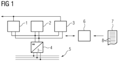
- An overall system comprises an electrolysis plant 1 as a subsystem.
- the electrolysis plant 1 produces hydrogen during operation.
- the overall system further comprises an electrical energy storage device 2 as a further subsystem.
- the overall system can include further subsystems, for example a plant in the steel industry or generally a plant that consumes electricity and/or hydrogen (not shown).
- the overall system also includes a hydrogen storage facility 3 as a further subsystem.
- the hydrogen storage facility 3 can be designed as a storage facility in the narrower sense, i.e. as a dedicated hydrogen storage facility.
- the pipeline network through which hydrogen is transported also has a certain storage capacity and can serve as a hydrogen storage facility 3 in the sense of the present invention.
- the hydrogen storage facility 3 can alternatively be arranged above ground or underground.
- the hydrogen storage 3 is connected directly or indirectly to the electrolysis plant 1 for receiving hydrogen and directly or indirectly to a hydrogen-consuming plant for releasing hydrogen. This is in FIG 1 indicated by the connecting line above the electrolysis plant 1 and the hydrogen storage 3. Due to the hydrogen storage 3, the operation of the electrolysis plant 1 - especially in conjunction with the hydrogen-consuming plant - can be designed more flexibly.
- the electrolysis system 1 and the electrical energy storage device 2 are connected to one another directly or indirectly to transmit electrical energy. They are also connected to an electrical supply network 5 - usually via a common converter unit 4, alternatively via their own converter units. Additional converter units can be arranged between the converter unit 4 and the electrical supply network 5.
- the converter unit 4 is preferably designed in such a way that the voltage applied to the electrolysis system 1 and the energy storage device 2 can be adjusted via it.
- the supply network 5 is usually a three-phase network and thus a multi-phase supply network.
- the three-phase network is often operated with a medium voltage in the range of 20 kV to 30 kV or with a high voltage of 110 kV.
- the overall system further comprises a control device 6.
- the control device 6 is programmed with a control program 7.
- the control program 7 comprises machine code 8 which can be processed by the control device 6. Due to the programming with the control program 7, the control device 6 processes the machine code 8.
- the processing of the machine code 8 by the control device 6 causes the control device 6 to control the overall system according to an operating method which is described below in connection with FIG 2 is explained in more detail.
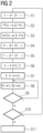
- a step S1 the control device 6 is informed of a current state Z of the overall system.
- the current state Z comprises a current partial state Z1, Z2 for the electrolysis system 1 and the energy storage device 2. If further partial systems are present, the state Z also comprises a current partial state for these partial systems.
- the partial state Z1 for the electrolysis plant 1 - hereinafter also referred to as plant state Z1 - can include, for example, a utilization and/or a temperature of the electrolysis plant 1 and/or a chemical composition of the electrolysis liquid of the electrolysis plant 1 and/or a wear state of the electrolysis plant 1.
- the partial state Z2 for the energy storage device 2 - hereinafter also referred to as storage state Z2 - includes at least the charge state of the energy storage device 2, i.e. the extent to which the energy storage device 2 is charged.
- the storage state Z2 can also include other variables, for example a temperature of the energy storage device 2 or a maximum possible or permissible charging and discharging current.
- the storage state Z2 can include the current current flow and/or a wear state of the energy storage device 2.
- the associated partial state includes at least the fill level of the hydrogen storage 3, i.e. the extent to which the hydrogen storage 3 is filled.
- the associated partial state can also include other variables, for example a temperature of the hydrogen storage 3 or a maximum possible or permissible flow of hydrogen when filling and emptying the hydrogen storage 3.
- a step S2 the control device 6 is informed of a desired production plan PP of the electrolysis system 1.
- the production plan PP can be specified to the control device 6 by an operator (not shown).
- the production plan PP determines, as a function of time t, to what extent and, if applicable, with what degree of purity hydrogen is to be produced by the electrolysis system 1.
- the production plan PP extends over a forecast horizon PH.
- the forecast horizon PH is generally at least several hours, often even in the range of several days.
- the production plan PP can also be determined by a production plan for other subsystems of the overall system, provided that these subsystems consume hydrogen.
- the control device 6 is informed of data D which determine at least one expected price P for electrical energy for the forecast horizon PH, provided that the electrical energy is drawn from the supply network 5.
- the expected price P is defined at least as a function of time t.
- the expected price P can depend on other facts, for example the amount of electrical energy drawn from the supply network 5. Electrical energy fed back into the supply network 5 is also often billed differently than electrical energy drawn from the supply network 5.
- the expected price P can also depend on the electrical power currently being drawn. For example, it can be the case that the price per MWh of electricity drawn is higher once a certain threshold value is exceeded, the higher the power drawn.
- the production plan PP and the data D for the price P of the control device 6 can initially be known for different time horizons in steps S2 and S3.
- the forecast horizon PH is determined by the smaller of the two time horizons.
- the control device 6 sets an operating mode B for the entire system for the forecast horizon PH.
- the operating mode B includes - analogous to the current state Z - a partial operating mode B1, B2, etc. for each of the subsystems 1, 2, etc.
- the partial operating modes B1, B2, etc. can be time-resolved to the second.
- the set operating modes B, B1, B2, etc. are initially only provisional.
- control device 6 When determining the plant operating mode B1, the control device 6 must ensure that the hydrogen requirements of other subsystems of the overall system are met, that the filling level of the hydrogen storage tank 3 does not fall below 0% and does not rise above 100%, and that the design limits of the electrolysis plant 1 are otherwise observed.
- electrolysis plant 1 may be sensible. However, it may also be sensible to vary the operation of the electrolysis plant 1 over time, since the costs for electrical energy often fluctuate greatly.
- the partial operating mode B2 for the energy storage device 2 - hereinafter also referred to as storage operating mode B2 - can be determined independently and often relatively flexibly by the control device 6. However, the control device 6 must ensure that the charge state of the energy storage device 2 does not fall below 0% and does not rise above 100% and that the design limits of the energy storage device 2 (for example the maximum charging current and the maximum discharging current) are adhered to.
- the partial operating mode for the hydrogen storage 3 - hereinafter also referred to as the hydrogen storage operating mode - often cannot be freely determined by the control device 6. Rather, it is determined by the system operating mode B1 and the operating modes of the hydrogen-consuming subsystems.
- the hydrogen storage 3 enables the decoupling of the operation of the electrolysis system 1 and the Hydrogen-consuming subsystems from each other and thus the flexible operation of the electrolysis plant 1.
- the control device 6 determines an expected final overall state Z' for the end of the forecast horizon PH.
- the expected final overall state Z' comprises - analogously to the current state Z - an expected final partial state Z1', Z2', etc. for each of the subsystems 1, 2, etc.
- the determination of the respective expected final partial state Z1', Z2', etc. is carried out by using the respective current partial state Z1, Z2, etc. and the respective partial operating mode B1, B2, etc.
- the control device 6 determines the respective expected final partial state Z1', Z2', etc. by updating the respective current partial state Z1, Z2, etc. based on the respective partial operating mode B1, B2, etc.
- the control device 6 determines the value of a cost function K.
- Various cost factors can be included in the cost function K.
- the cost function K is defined as a weighted or unweighted sum of the individual cost factors. Possible cost factors include, for example, the costs for purchasing electrical energy from the supply network 5, the operating modes B1, B2, etc. of the subsystems 1, 2, etc., evaluations of the expected final states Z1', Z2', etc. and a productivity of the electrolysis plant 1.
- the control device 6 can, for example, use the determined partial operating modes B1, B2, etc. to determine the purchase of electrical energy from the supply network 5 and, based on this, in conjunction with the known price P, determine the associated costs.
- the determination can be made with the same time resolution with which the partial operating modes B1, B2, etc. are determined, for example to the second.
- the determination can also be made with a coarser time resolution, for example with a resolution of 1 minute or 15 minutes. It is also possible to initially work with a high time resolution, for example to the second, but then to carry out statistical evaluations for longer periods of time (for example 1 minute, 5 minutes, 15 minutes), for example to determine mean values, maximum values, minimum values, dispersions, etc.
- the efficiency of the converter unit 4 can also be taken into account in the costs, whereby the efficiency of the converter unit 4 can also depend on the operating state of the converter unit 4.
- the plant operating mode B1 can be evaluated, for example, in terms of productivity, resource-saving operation, an assessment of the wear and tear of the electrolysis plant 1, etc. It can also be assessed that, for example, when the output is reduced, the hydrogen is often contaminated to a greater extent.
- the production of hydrogen in each electrolysis cell is essentially proportional to the flowing current.
- the voltage dropping across an individual electrolysis cell is a function of the current.
- the voltage can also depend on the temperature of the electrolysis liquid and the wear of a membrane of the respective electrolysis cell.
- the efficiency with which each electrolysis cell works corresponds essentially to the voltage dropping across the respective electrolysis cell.
- the wear in turn, depends on the temperature and the current. Wear that occurs due to a change in the operation of the respective electrolysis cell can also be determined and taken into account.
- the contamination of the hydrogen produced is also a function of the current. As required, either the contamination of the hydrogen as such or the effort to clean the hydrogen can be assessed with corresponding costs.
- the costs for operating a single electrolysis cell can be evaluated in this way.
- the evaluation can, for example, include the costs for the consumption and aging of the electrolyte and the wear and tear on the electrodes and membrane of the electrolysis cell. A current ripple can also be taken into account.
- the costs of a currentless (non-operating) electrolysis cell can also be evaluated.
- the costs for operating electrolysis system 1 are the sum of all electrolysis cells in electrolysis system 1.
- the voltage of an individual battery cell depends on the charge of the respective battery cell and - due to the internal resistance - on the current through the respective battery cell.
- the charge state of the respective battery cell is determined by integrating over the current, starting from a known initial value.
- the internal resistance can depend, for example, on the temperature and wear of the respective battery cell, and possibly also on the charge state.
- the wear is also dependent on the current through the respective battery cell and on the charge state of the respective battery cell. There may also be a dependency on other variables, for example on existing wear or on the temperature.
- the costs for operating a single battery cell can thus be assessed.
- the assessment can include in particular the costs for aging.
- a current ripple can also be taken into account.
- the costs of a battery cell without current can also be assessed.
- the costs for operating energy storage unit 2 are the sum of all battery cells in energy storage unit 2.
- the hydrogen storage unit 3 in particular generally requires relatively little energy, so that the energy requirement can be neglected if necessary or only needs to be taken into account if performance limits are exceeded integrally - seen across all subsystems that consume electrical energy.
- the cost function K preferably includes losses of hydrogen in the hydrogen storage unit 3. This is because such losses - which of course incur costs - cannot simply be ignored. In relation to one day, they can be in the range of up to 0.5% of the amount of hydrogen stored in the hydrogen storage unit 3.
- the evaluation of the expected final system state Z1' can include a portion that is determined, for example, by using an energetic state of the electrolysis system 1.
- the control device 6 is able to determine the evaluation of the expected final system state Z1' taking into account an amount of energy that must be applied during the subsequent operation of the electrolysis system 1 beyond the forecast horizon PH, for example in order to heat the electrolysis system 1 back up to its operating temperature. Concentrations of electrolyte fluids can also be included in the evaluation.
- the evaluation of the expected final storage state Z2' can include a portion that takes into account the wear and tear incurred by the operation of the energy storage device 2, i.e. the costs due to the wear and tear that occurs during the production horizon PH due to the storage operating mode B2.
- the evaluation of the productivity of the electrolysis plant 1 is usually relatively simple. It is generally better (i.e. the corresponding cost factor is smaller) the larger the amount of hydrogen produced in a certain unit of time. In the simplest case, the corresponding cost factor is proportional to the time required to produce a previously determined amount of hydrogen.
- cost function K Other cost factors can also be included in the cost function K. Some possible additional cost factors are discussed below as examples.
- a cost factor can be taken into account that represents the costs for operating additional subsystems, i.e. the costs that arise for the forecast horizon PH under consideration, but without taking into account the costs for electrical energy.
- the costs for operating the additional subsystems can, for example, include the costs for required input materials such as raw materials and process media or the costs for processing process media or costs due to environmental pollution.
- the cost factor for operating the additional subsystems can also include depreciation.
- cost factors can also be taken into account which represent the costs for the other operations of the electrolysis plant 1, the energy storage plant 2 and the hydrogen storage plant 3.
- a step S7 the control device 6 solves an optimization problem.
- the solution to the optimization problem is the combination of those partial operating modes B1, B2, etc. - each considered over the production horizon PH - in which the cost function K is minimal overall.
- the cost function K is therefore a functional that is to be minimized and is calculated on the basis of an initial value problem with boundary conditions.
- the control device 6 varies the partial operating modes B1, B2, etc. for the forecast horizon PH. The variation takes place taking into account the production plan PP.
- the control device 10 can also take additional conditions into account.
- conditions can be, for example, performance limits of the system 1 and the energy storage device 2, for example a minimum permissible and a maximum permissible state of charge, a maximum permissible charging current and a maximum permissible discharging current for the energy storage device 9.
- Other conditions are also possible, for example certain specifications for the expected final states Z1', Z2', etc. It can also be required that no energy is fed into the supply network 5 or that the energy drawn from the supply network 5 does not exceed a predetermined maximum value.
- the expected final state Z2' for the energy storage device 2 can, for example - either as a point value or as a framework specification - include a state of charge of the energy storage device 2 that must be met at the end of the forecast horizon PH.
- the consideration of such conditions can be achieved in particular by so-called inequality constraints
- the control device 6 can also take into account an average charge level of the electrical energy storage device 2 when varying the partial operating modes B1, B2, etc. This can be taken into account by including deviations from the average charge level in the cost function K with weighted factors - albeit relatively small ones - and thus being "penalized".
- step S7 With the execution of step S7, the varied and thus optimized partial operating modes B1, B2, etc. are determined.
- the control device 6 can therefore operate the subsystems 1, 2, etc. in accordance with the varied partial operating modes B1, B2, etc. in a step S8. This is initially done for the beginning of the forecast horizon PH.
- step S9 the control device 6 checks whether new information is available to it. If this is not the case, the control device 6 returns to step S8.
- step S8 is carried out again, the control device 6 continues to operate the subsystems 1, 2, etc. according to the varied partial operating modes B1, B2, etc. In doing so, it takes into account the progress in time t.
- step S10 the control device 6 checks whether the information is a command to terminate the operation of the entire system. If this is the case, the control device 6 terminates the operation of the entire system in a step S11. Otherwise, the control device 6 goes back to step S1. Depending on the type of new information, the control device 6 can alternatively go back to step S2 or step S3.
- the procedure according to FIG 2 the determination of the partial operating modes B1, B2 is repeated again and again with a specific forecast horizon PH.
- the determination is therefore carried out in the sense of a permanent forecast and is continuously adjusted to the expected price P and the production plan PP.
- the control device 6 implements a model of the electrolysis plant 1.
- the model of the electrolysis plant 1 models the energy efficiency and the wear of the electrolysis plant 1.
- the wear determined depends on the planned operation of the electrolysis plant 1.
- the wear can depend in particular in a non-linear manner on the plant operating mode B1.
- the evaluation of the expected final plant state Z1' can depend, for example, on the concentrations of process media (in particular electrolytes) expected for the end of the forecast horizon PH and the temperature of the electrolysis plant 1. There can also be a dependence on wear.
- the determination of the cost factor for the operation of the energy storage system 2 and the evaluation of the expected final storage state Z2' can be carried out in an analogous manner.
- control device 6 for the electrolysis system 1 and the electrical energy storage device 2 knows the efficiency, possibly depending on the operating state, the maximum capacity and the maximum possible rate of change of the operation of the electrolysis system 1 or the electrical energy storage device 2. These facts are also used within the framework of the respective model.
- FIGS 3 and 4 Two particularly preferred embodiments of the two basic subsystems 1, 2 are explained, i.e. the electrolysis system 1 and the energy storage 2.
- the electrolysis plant 1 and the energy storage system 2 are integrated into each other as far as the electrical circuitry is concerned.
- electrolysis plant 1 has the following FIGS 3 and 4 several electrolysis blocks 10.
- the energy storage device 2 also has several battery modules 11.
- the battery modules 11 are each connected to one of the electrolysis blocks 10 via a respective converter circuit 12.
- the number of electrolysis blocks 10 can be determined as required. For example, it can be 10, 15, 20, 50 or 100. Other numbers are also possible, be it less than 10, be it more than 100, be it between 10 and 100. As a rule, however, the number of electrolysis blocks 10 will be between 10 and 30. Regardless of the number of electrolysis blocks 10, however, the same number of battery modules 11 and converter circuits 12 are always present, so that exactly this number of groups, each consisting of one (1) electrolysis block 10, one (1) battery module 11 and one (1) converter circuit 12, can be formed.
- the electrolysis blocks 10 form an (electrical) series circuit, which is connected to the supply network 5 via the converter unit 4.
- the battery modules 11 are in the design according to FIG 3 thus, so to speak, an appendage of the respective electrolysis block 10.
- the battery modules 11 form an (electrical) series connection, which is connected to the supply network 5 via the converter unit 4.
- the electrolysis blocks 10 are thus, so to speak, appendages of the respective battery module 11.
- the electrolysis blocks 10 are according to FIG 5 each designed as a parallel connection of a number of electrolysis strands 13.
- the number of electrolysis strands 13 per electrolysis block 10 can be (only) 1. In this case, the parallel connection is degenerate. However, the electrolysis blocks 10 often have several electrolysis strands 13 each, so that a true parallel connection exists. As a rule, the number of electrolysis strands 13 per electrolysis block 10 is the same for all electrolysis blocks 10. As a rule, the number of electrolysis strands 13 per electrolysis block 10 will be between 10 and 30.
- electrolysis strings 13 are FIG 5 in turn, each designed as a series connection of several electrolysis cells 14.
- the electrolysis cells 14 of the respective electrolysis line 13 are arranged one behind the other both electrically and mechanically and in terms of fluid technology.
- a single electrolysis cell 14 is the smallest possible structural unit. It is characterized in particular by its electrochemical operating voltage, which is usually in the lower single-digit volt range, for example between 1.5 V and 2.0 V.
- the number of electrolysis cells 14 per electrolysis string 13 can be determined as required. For example, it can be 50, 80, 100, 120, 150 or 200 electrolysis cells 14. Other numbers are also possible, be it less than 50, more than 200, or between 50 and 200. Within the respective electrolysis block 10, the number of electrolysis cells 14 per electrolysis string 13 is uniformly the same. It can vary from electrolysis block 10 to electrolysis block 10. As a rule, however, the number of electrolysis cells 14 per electrolysis string 13 will be between 50 and 250, in particular between 100 and 200.
- the product of the number of electrolysis blocks 10 and the number of electrolysis cells 14 per electrolysis string 13 is often in the range between 500 and 3000, in particular between 1000 and 2000.
- the interior of the electrolysis blocks 10 or the electrolysis strands 13 cannot be easily accessed.
- the electrolysis blocks 10 or the electrolysis strands 13 can have a solid steel outer shell, so that only electrical connections for power and sensors as well as inlets and outlets for the electrolyte and produced gases are accessible. Due to the arrangement in the outer shell, the electrolysis can take place under pressure, so that, for example, energy can be saved for subsequent compression of the hydrogen. Otherwise, this energy would be required, for example, to store the hydrogen in the hydrogen storage 3.
- the battery modules 11 according to FIG 6 each have a series connection of several battery blocks 15.
- the number of battery blocks 15 per battery module 11 can be determined as required. For example, it can be 50, 80, 100, 120, 150 or 200 battery blocks 15. Other numbers are also possible, be it less than 50, more than 200, or between 50 and 200.
- the number of battery blocks 15 is often the same for all battery modules 11. However, this is not mandatory. Rather, the number of battery blocks 15 can vary from battery module 11 to battery module 11. As a rule, however, the number of battery blocks 15 per battery module 11 will be between 50 and 250, in particular between 100 and 200.
- the battery blocks 15 in turn have a number of battery cells 16 connected in parallel.
- the number of battery cells 16 per battery block 15 can be (only) 1.
- the parallel connection is degenerate.
- the battery blocks 15 often have several battery cells 16 each, so that a true parallel connection exists.
- the number of battery cells 16 per battery block 15 is the same for all battery blocks 15.
- the number of battery cells 16 per battery block 15 will be between 50 and 500, in particular between 100 and 400.
- a single battery cell 16 is the smallest possible structural unit. It is characterized in particular by its electrochemical operating voltage, which is usually also in the lower single-digit volt range, for example between 1.2 V and 5.0 V, especially in the case of a Li cell between 3.2 V and 4.2 V.
- the battery modules 11 each have a balancing circuit 17.
- the respective balancing circuit 17 effects a balancing of the charge states of the battery blocks 15 of the respective battery module 11 within the series-connected battery blocks 15 of the respective battery module 11. Balancing circuits 17 are known as such.
- the converter circuits 12 can be designed as required.
- the converter circuits 12 can be designed as shown in FIG 7 be designed as a synchronous converter.
- the respective converter circuit 12 comprises two electronic switching elements 18 (as shown in FIG 7 MOSFETs, but other semiconductor switches are also possible) and a choke 19.
- the FIG 7 The capacitor 20 shown is often present, but not mandatory.
- the converter circuits 12 can be arranged as shown in the FIGS 8 and 9 designed as a step-up converter or as a step-down converter. As a rule, the converter circuits 12 are designed uniformly.
- the converter circuits 12 When the converter circuits 12 are designed as synchronous converters, the unit with the higher operating voltage is usually arranged on the input side of the respective converter circuit 12. Depending on the design of the electrolysis blocks 10 and the battery modules 11, this can be either the respective electrolysis block 10 or the respective battery module 11.
- the converter circuits 12 When the converter circuits 12 are designed as step-up converters or step-down converters, the Direction of energy flow is determined. In this case, the respective battery module 11 must always be arranged on the input side of the respective converter circuit 12.
- the design of the converter devices 12 as step-up converters or step-down converters is particularly important in the design according to FIG 4 possible.
- n groups each consisting of one (1) electrolysis block 10, one (1) battery module 11 and one (1) converter circuit 12, there are n+1 control variables to be set.
- One of the control variables is the operating mode of the converter unit 4. Its control determines the extent to which energy is supplied to the electrolysis system 1 and the energy storage unit 2 (this value can also be negative for a short time).
- the other n control variables are the operating modes of the converter circuits 12, in particular their pulse width ratios.
- the operating modes of the converter circuits 12 determine the extent to which the current delivered by the converter unit 4 is distributed between the respective electrolysis block 10 and the respective battery module 11. The distribution can be uniformly the same for the n groups. However, this is not absolutely necessary.
- the converter unit 4 and the converter circuits 12 should be controlled in such a way that a certain voltage is applied to the unit consisting of the electrolysis system 1 and the energy storage device 2 and the currents of the battery modules 11 have certain values.
- the voltages and currents are recorded, as far as necessary, and integrated into corresponding control circuits for determining the controls of the converter unit 4 and the converter circuits 12.
- the explained, nested structure of the electrolysis system 1 and the energy storage device 2 is particularly advantageous because it is modular. If - for example - an individual electrolysis block 10 and/or an individual battery module 11 and/or an individual converter circuit 12 needs to be serviced, repaired or replaced, the corresponding group can be bridged via switching devices (not shown). The other groups, however, could continue to operate, although the control of the converter unit 4 and/or the remaining converter circuits 12 may need to be adjusted, but can often be left unchanged or almost unchanged. Above all, however, the electrolysis system 1 and the energy storage device 2 can continue to operate as a whole.
- the present invention has many advantages. In particular, a comprehensive optimization of the operation of the overall system, consisting of the subsystems 1, 2, etc., is possible.
Landscapes
- Engineering & Computer Science (AREA)
- Power Engineering (AREA)
- Electrolytic Production Of Non-Metals, Compounds, Apparatuses Therefor (AREA)
- Charge And Discharge Circuits For Batteries Or The Like (AREA)
Priority Applications (6)
| Application Number | Priority Date | Filing Date | Title |
|---|---|---|---|
| EP23151358.1A EP4401265A1 (fr) | 2023-01-12 | 2023-01-12 | Fonctionnement optimisé d'une installation d'électrolyse et d'un accumulateur d'énergie électrique |
| JP2025540903A JP2026500871A (ja) | 2023-01-12 | 2023-12-20 | 電気分解装置と電気エネルギー貯蔵装置との組み合わせ |
| PCT/EP2023/086932 WO2024149586A1 (fr) | 2023-01-12 | 2023-12-20 | Combinaison d'une installation d'électrolyse et d'un accumulateur d'énergie électrique |
| EP23837230.4A EP4649565A1 (fr) | 2023-01-12 | 2023-12-20 | Combinaison d'une installation d'électrolyse et d'un accumulateur d'énergie électrique |
| CN202380091291.7A CN120513561A (zh) | 2023-01-12 | 2023-12-20 | 电解系统和电能储存器的组合 |
| MX2025007792A MX2025007792A (es) | 2023-01-12 | 2025-07-02 | Combinacion de un sistema de electrolisis y un almacenador de energia electrica |
Applications Claiming Priority (1)
| Application Number | Priority Date | Filing Date | Title |
|---|---|---|---|
| EP23151358.1A EP4401265A1 (fr) | 2023-01-12 | 2023-01-12 | Fonctionnement optimisé d'une installation d'électrolyse et d'un accumulateur d'énergie électrique |
Publications (1)
| Publication Number | Publication Date |
|---|---|
| EP4401265A1 true EP4401265A1 (fr) | 2024-07-17 |
Family
ID=84943717
Family Applications (2)
| Application Number | Title | Priority Date | Filing Date |
|---|---|---|---|
| EP23151358.1A Withdrawn EP4401265A1 (fr) | 2023-01-12 | 2023-01-12 | Fonctionnement optimisé d'une installation d'électrolyse et d'un accumulateur d'énergie électrique |
| EP23837230.4A Pending EP4649565A1 (fr) | 2023-01-12 | 2023-12-20 | Combinaison d'une installation d'électrolyse et d'un accumulateur d'énergie électrique |
Family Applications After (1)
| Application Number | Title | Priority Date | Filing Date |
|---|---|---|---|
| EP23837230.4A Pending EP4649565A1 (fr) | 2023-01-12 | 2023-12-20 | Combinaison d'une installation d'électrolyse et d'un accumulateur d'énergie électrique |
Country Status (5)
| Country | Link |
|---|---|
| EP (2) | EP4401265A1 (fr) |
| JP (1) | JP2026500871A (fr) |
| CN (1) | CN120513561A (fr) |
| MX (1) | MX2025007792A (fr) |
| WO (1) | WO2024149586A1 (fr) |
Citations (5)
| Publication number | Priority date | Publication date | Assignee | Title |
|---|---|---|---|---|
| US7444189B1 (en) * | 2004-06-15 | 2008-10-28 | John Joseph Marhoefer | Method and apparatus for simultaneous optimization of distributed generation and hydrogen production |
| US8288888B2 (en) | 2008-10-30 | 2012-10-16 | Next Hydrogen Corporation | Power dispatch system for electrolytic production of hydrogen from wind power |
| DE102012113049A1 (de) * | 2012-12-21 | 2014-06-26 | Evonik Industries Ag | Verfahren zum Betreiben von Energiespeichern |
| US20200106294A1 (en) * | 2018-09-28 | 2020-04-02 | Johnson Controls Technology Company | Photovoltaic energy system with stationary energy storage control and power factor correction |
| US20220302708A1 (en) * | 2021-03-17 | 2022-09-22 | Kabushiki Kaisha Toshiba | Information processing apparatus, information processing method, non-transitory computer readable medium, and information processing system |
Family Cites Families (2)
| Publication number | Priority date | Publication date | Assignee | Title |
|---|---|---|---|---|
| CN104319410B (zh) * | 2010-01-25 | 2017-01-11 | 雷蒙特亚特特拉维夫大学有限公司 | 在燃料电池堆内维持不同电解质和气体压力的方法 |
| WO2021102405A1 (fr) * | 2019-11-21 | 2021-05-27 | Ohmium International, Inc. | Systèmes modulaires de génération d'hydrogène et leurs procédés de fonctionnement |
-
2023
- 2023-01-12 EP EP23151358.1A patent/EP4401265A1/fr not_active Withdrawn
- 2023-12-20 CN CN202380091291.7A patent/CN120513561A/zh active Pending
- 2023-12-20 WO PCT/EP2023/086932 patent/WO2024149586A1/fr not_active Ceased
- 2023-12-20 EP EP23837230.4A patent/EP4649565A1/fr active Pending
- 2023-12-20 JP JP2025540903A patent/JP2026500871A/ja active Pending
-
2025
- 2025-07-02 MX MX2025007792A patent/MX2025007792A/es unknown
Patent Citations (5)
| Publication number | Priority date | Publication date | Assignee | Title |
|---|---|---|---|---|
| US7444189B1 (en) * | 2004-06-15 | 2008-10-28 | John Joseph Marhoefer | Method and apparatus for simultaneous optimization of distributed generation and hydrogen production |
| US8288888B2 (en) | 2008-10-30 | 2012-10-16 | Next Hydrogen Corporation | Power dispatch system for electrolytic production of hydrogen from wind power |
| DE102012113049A1 (de) * | 2012-12-21 | 2014-06-26 | Evonik Industries Ag | Verfahren zum Betreiben von Energiespeichern |
| US20200106294A1 (en) * | 2018-09-28 | 2020-04-02 | Johnson Controls Technology Company | Photovoltaic energy system with stationary energy storage control and power factor correction |
| US20220302708A1 (en) * | 2021-03-17 | 2022-09-22 | Kabushiki Kaisha Toshiba | Information processing apparatus, information processing method, non-transitory computer readable medium, and information processing system |
Non-Patent Citations (4)
| Title |
|---|
| FLETCHER, R.: "Practical Methods on Optimization", 1987, JOHN WILEY INC. |
| HINTERMÜLLER, M.STADLER, G.: "A semi-smooth Newton methods for linear-quadratic control problems", ZEITSCHRIFT FÜR ANGEWANDTE MATHEMATIK UND MECHANIK (ZAMM, vol. 83-4, 2003, pages 219 - 237 |
| ITO, K.KUNISCH, K.: "Semi-smooth Newton methods for state-constrained optimal control problems", SYSTEMS AND CONTROL LETTERS, vol. 50, 2003, pages 221 - 228 |
| STAHLEISEN, GRÜNE ENERGIEVERSORGUNG DER STAHLINDUSTRIE, August 2022 (2022-08-01), pages 22 - 24 |
Also Published As
| Publication number | Publication date |
|---|---|
| JP2026500871A (ja) | 2026-01-08 |
| WO2024149586A1 (fr) | 2024-07-18 |
| MX2025007792A (es) | 2025-08-01 |
| CN120513561A (zh) | 2025-08-19 |
| EP4649565A1 (fr) | 2025-11-19 |
Similar Documents
| Publication | Publication Date | Title |
|---|---|---|
| DE102022204103A1 (de) | Verfahren zum Betreiben einer Ammoniaksynthese mit schwankender Auslastung | |
| WO2014095343A2 (fr) | Procédé de fonctionnement d'accumulateurs d'énergie | |
| EP3382841B1 (fr) | Utilisation hybride d'accumulateurs d'énergie | |
| DE102009054078A1 (de) | Batterieproduktionseinrichtung | |
| WO2023198465A1 (fr) | Procédé pour déterminer une valeur théorique d'une puissance de charge pour une charge d'une batterie d'un véhicule au moyen d'un dispositif de charge | |
| EP4401265A1 (fr) | Fonctionnement optimisé d'une installation d'électrolyse et d'un accumulateur d'énergie électrique | |
| EP2917959B1 (fr) | Procédé de fourniture d'énergie électrique à un consommateur | |
| WO2019211034A1 (fr) | Procédé de régulation en temps réel d'un système d'alimentation et de distribution d'énergie | |
| EP4054045A1 (fr) | Procédé et dispositif de commande permettant de commander les flux de puissance entre plusieurs systèmes énergétiques | |
| EP3042433B1 (fr) | Procédé et dispositif permettant la gestion optimale pour un système d'accumulation d'un système photovoltaïque | |
| DE102019125200A1 (de) | Verfahren zum Steuern eines Speichersystems und Energie-Management-System für ein Speichersystem | |
| EP4492611A1 (fr) | Procédé et appareil pour faire fonctionner une batterie dans une communauté d'énergie renouvelable | |
| DE102019121990A1 (de) | Verfahren zur Modellierung einer oder mehrerer Energiewandlungsanlagen in einem Energiemanagementsystem | |
| EP4443352A1 (fr) | Fonctionnement économique d'une installation dri et de plus de sous-systèmes d'un système global | |
| EP4649564A1 (fr) | Fonctionnement économique d'une installation de l'industrie sidérurgique et d'autres systèmes partiels d'un système global | |
| EP4401264A1 (fr) | Fonctionnement économique d'une installation de l'industrie sidérurgique et de plus de sous-systèmes d'un système global | |
| DE102015110029A1 (de) | Verfahren zur steuerung eines verbrauchers | |
| EP4085504B1 (fr) | Procédé de gestion d'énergie et système de gestion d'énergie | |
| EP4443688A1 (fr) | Fonctionnement économique d'une installation de l'industrie sidérurgique et de plus de sous-systèmes d'un système global | |
| EP4690415A1 (fr) | Fonctionnement économique d'une installation de l'industrie métallurgique et de sous-systèmes supplémentaires d'un système complet | |
| EP4336773A1 (fr) | Système et procédé pour effectuer des calculs associés à une chaîne de blocs | |
| EP4498557A1 (fr) | Fonctionnement économique d'une installation de l'industrie métallique et de plus de sous-systèmes d'un système global comprenant l'installation | |
| DE102023208469A1 (de) | Verfahren zum Betreiben einer Elektrolyseanlage, Prozessleitsystem | |
| DE102023208424A1 (de) | Verfahren zum Betreiben einer Elektrolyseanlage, Prozessleitsystem | |
| WO2026003347A1 (fr) | Procédé et système de détermination d'un point de fonctionnement d'un système de synthèse d'ammoniac ayant une alimentation électrique pour fournir de l'hydrogène, ladite alimentation électrique comprenant au moins une source d'énergie renouvelable |
Legal Events
| Date | Code | Title | Description |
|---|---|---|---|
| PUAI | Public reference made under article 153(3) epc to a published international application that has entered the european phase |
Free format text: ORIGINAL CODE: 0009012 |
|
| STAA | Information on the status of an ep patent application or granted ep patent |
Free format text: STATUS: THE APPLICATION HAS BEEN PUBLISHED |
|
| AK | Designated contracting states |
Kind code of ref document: A1 Designated state(s): AL AT BE BG CH CY CZ DE DK EE ES FI FR GB GR HR HU IE IS IT LI LT LU LV MC ME MK MT NL NO PL PT RO RS SE SI SK SM TR |
|
| STAA | Information on the status of an ep patent application or granted ep patent |
Free format text: STATUS: THE APPLICATION IS DEEMED TO BE WITHDRAWN |
|
| 18D | Application deemed to be withdrawn |
Effective date: 20250118 |