EP4401367A1 - Kommunikationsverfahren und vorrichtung für wifi-system - Google Patents
Kommunikationsverfahren und vorrichtung für wifi-system Download PDFInfo
- Publication number
- EP4401367A1 EP4401367A1 EP21959001.5A EP21959001A EP4401367A1 EP 4401367 A1 EP4401367 A1 EP 4401367A1 EP 21959001 A EP21959001 A EP 21959001A EP 4401367 A1 EP4401367 A1 EP 4401367A1
- Authority
- EP
- European Patent Office
- Prior art keywords
- extension
- code
- data code
- coding
- code blocks
- Prior art date
- Legal status (The legal status is an assumption and is not a legal conclusion. Google has not performed a legal analysis and makes no representation as to the accuracy of the status listed.)
- Pending
Links
- 238000004891 communication Methods 0.000 title claims abstract description 207
- 238000000034 method Methods 0.000 title claims abstract description 126
- 230000007480 spreading Effects 0.000 claims description 92
- 238000004590 computer program Methods 0.000 claims description 17
- 238000005516 engineering process Methods 0.000 abstract description 16
- 230000035515 penetration Effects 0.000 abstract description 5
- 230000006870 function Effects 0.000 description 59
- 238000012545 processing Methods 0.000 description 46
- 238000010586 diagram Methods 0.000 description 29
- 230000008569 process Effects 0.000 description 25
- 230000005540 biological transmission Effects 0.000 description 24
- 238000001514 detection method Methods 0.000 description 23
- 230000000694 effects Effects 0.000 description 18
- 230000000875 corresponding effect Effects 0.000 description 15
- 238000013461 design Methods 0.000 description 14
- 230000002596 correlated effect Effects 0.000 description 12
- 238000010295 mobile communication Methods 0.000 description 10
- 238000004422 calculation algorithm Methods 0.000 description 9
- 230000011664 signaling Effects 0.000 description 8
- 238000012986 modification Methods 0.000 description 5
- 230000004048 modification Effects 0.000 description 5
- 230000003287 optical effect Effects 0.000 description 5
- 230000000295 complement effect Effects 0.000 description 4
- 230000010363 phase shift Effects 0.000 description 4
- 230000003068 static effect Effects 0.000 description 4
- 230000003321 amplification Effects 0.000 description 2
- 230000003416 augmentation Effects 0.000 description 2
- 125000004122 cyclic group Chemical group 0.000 description 2
- 238000001914 filtration Methods 0.000 description 2
- 239000004973 liquid crystal related substance Substances 0.000 description 2
- 230000007774 longterm Effects 0.000 description 2
- 238000007726 management method Methods 0.000 description 2
- 238000003199 nucleic acid amplification method Methods 0.000 description 2
- 230000005855 radiation Effects 0.000 description 2
- 230000002441 reversible effect Effects 0.000 description 2
- 238000001228 spectrum Methods 0.000 description 2
- 230000001360 synchronised effect Effects 0.000 description 2
- 238000000342 Monte Carlo simulation Methods 0.000 description 1
- 230000001133 acceleration Effects 0.000 description 1
- 238000005311 autocorrelation function Methods 0.000 description 1
- 210000000988 bone and bone Anatomy 0.000 description 1
- 238000004364 calculation method Methods 0.000 description 1
- 239000003795 chemical substances by application Substances 0.000 description 1
- 238000010276 construction Methods 0.000 description 1
- 238000013500 data storage Methods 0.000 description 1
- 230000001419 dependent effect Effects 0.000 description 1
- 238000011156 evaluation Methods 0.000 description 1
- 239000013307 optical fiber Substances 0.000 description 1
- 230000000737 periodic effect Effects 0.000 description 1
- 230000011218 segmentation Effects 0.000 description 1
- 239000004065 semiconductor Substances 0.000 description 1
- 230000003595 spectral effect Effects 0.000 description 1
Images


Classifications
-
- H—ELECTRICITY
- H04—ELECTRIC COMMUNICATION TECHNIQUE
- H04J—MULTIPLEX COMMUNICATION
- H04J3/00—Time-division multiplex systems
- H04J3/02—Details
- H04J3/06—Synchronising arrangements
- H04J3/0602—Systems characterised by the synchronising information used
- H04J3/0605—Special codes used as synchronising signal
-
- H—ELECTRICITY
- H04—ELECTRIC COMMUNICATION TECHNIQUE
- H04B—TRANSMISSION
- H04B1/00—Details of transmission systems, not covered by a single one of groups H04B3/00 - H04B13/00; Details of transmission systems not characterised by the medium used for transmission
- H04B1/69—Spread spectrum techniques
- H04B1/707—Spread spectrum techniques using direct sequence modulation
- H04B1/7073—Synchronisation aspects
-
- H—ELECTRICITY
- H04—ELECTRIC COMMUNICATION TECHNIQUE
- H04J—MULTIPLEX COMMUNICATION
- H04J13/00—Code division multiplex systems
- H04J13/10—Code generation
- H04J13/102—Combining codes
-
- H—ELECTRICITY
- H04—ELECTRIC COMMUNICATION TECHNIQUE
- H04L—TRANSMISSION OF DIGITAL INFORMATION, e.g. TELEGRAPHIC COMMUNICATION
- H04L1/00—Arrangements for detecting or preventing errors in the information received
- H04L1/0001—Systems modifying transmission characteristics according to link quality, e.g. power backoff
- H04L1/0002—Systems modifying transmission characteristics according to link quality, e.g. power backoff by adapting the transmission rate
- H04L1/0003—Systems modifying transmission characteristics according to link quality, e.g. power backoff by adapting the transmission rate by switching between different modulation schemes
-
- H—ELECTRICITY
- H04—ELECTRIC COMMUNICATION TECHNIQUE
- H04L—TRANSMISSION OF DIGITAL INFORMATION, e.g. TELEGRAPHIC COMMUNICATION
- H04L1/00—Arrangements for detecting or preventing errors in the information received
- H04L1/0001—Systems modifying transmission characteristics according to link quality, e.g. power backoff
- H04L1/0023—Systems modifying transmission characteristics according to link quality, e.g. power backoff characterised by the signalling
- H04L1/0025—Transmission of mode-switching indication
-
- H—ELECTRICITY
- H04—ELECTRIC COMMUNICATION TECHNIQUE
- H04L—TRANSMISSION OF DIGITAL INFORMATION, e.g. TELEGRAPHIC COMMUNICATION
- H04L1/00—Arrangements for detecting or preventing errors in the information received
- H04L1/0001—Systems modifying transmission characteristics according to link quality, e.g. power backoff
- H04L1/0023—Systems modifying transmission characteristics according to link quality, e.g. power backoff characterised by the signalling
- H04L1/0028—Formatting
- H04L1/0031—Multiple signaling transmission
-
- H—ELECTRICITY
- H04—ELECTRIC COMMUNICATION TECHNIQUE
- H04L—TRANSMISSION OF DIGITAL INFORMATION, e.g. TELEGRAPHIC COMMUNICATION
- H04L1/00—Arrangements for detecting or preventing errors in the information received
- H04L1/004—Arrangements for detecting or preventing errors in the information received by using forward error control
- H04L1/0056—Systems characterized by the type of code used
- H04L1/0067—Rate matching
-
- H—ELECTRICITY
- H04—ELECTRIC COMMUNICATION TECHNIQUE
- H04L—TRANSMISSION OF DIGITAL INFORMATION, e.g. TELEGRAPHIC COMMUNICATION
- H04L1/00—Arrangements for detecting or preventing errors in the information received
- H04L1/004—Arrangements for detecting or preventing errors in the information received by using forward error control
- H04L1/0075—Transmission of coding parameters to receiver
-
- H—ELECTRICITY
- H04—ELECTRIC COMMUNICATION TECHNIQUE
- H04L—TRANSMISSION OF DIGITAL INFORMATION, e.g. TELEGRAPHIC COMMUNICATION
- H04L27/00—Modulated-carrier systems
- H04L27/26—Systems using multi-frequency codes
- H04L27/2601—Multicarrier modulation systems
- H04L27/2602—Signal structure
-
- H—ELECTRICITY
- H04—ELECTRIC COMMUNICATION TECHNIQUE
- H04L—TRANSMISSION OF DIGITAL INFORMATION, e.g. TELEGRAPHIC COMMUNICATION
- H04L27/00—Modulated-carrier systems
- H04L27/26—Systems using multi-frequency codes
- H04L27/2601—Multicarrier modulation systems
- H04L27/2602—Signal structure
- H04L27/261—Details of reference signals
- H04L27/2613—Structure of the reference signals
- H04L27/26132—Structure of the reference signals using repetition
-
- H—ELECTRICITY
- H04—ELECTRIC COMMUNICATION TECHNIQUE
- H04L—TRANSMISSION OF DIGITAL INFORMATION, e.g. TELEGRAPHIC COMMUNICATION
- H04L27/00—Modulated-carrier systems
- H04L27/26—Systems using multi-frequency codes
- H04L27/2601—Multicarrier modulation systems
- H04L27/2602—Signal structure
- H04L27/261—Details of reference signals
- H04L27/2613—Structure of the reference signals
- H04L27/26134—Pilot insertion in the transmitter chain, e.g. pilot overlapping with data, insertion in time or frequency domain
-
- H—ELECTRICITY
- H04—ELECTRIC COMMUNICATION TECHNIQUE
- H04L—TRANSMISSION OF DIGITAL INFORMATION, e.g. TELEGRAPHIC COMMUNICATION
- H04L27/00—Modulated-carrier systems
- H04L27/26—Systems using multi-frequency codes
- H04L27/2601—Multicarrier modulation systems
- H04L27/2626—Arrangements specific to the transmitter only
- H04L27/2627—Modulators
- H04L27/2634—Inverse fast Fourier transform [IFFT] or inverse discrete Fourier transform [IDFT] modulators in combination with other circuits for modulation
-
- H—ELECTRICITY
- H04—ELECTRIC COMMUNICATION TECHNIQUE
- H04L—TRANSMISSION OF DIGITAL INFORMATION, e.g. TELEGRAPHIC COMMUNICATION
- H04L5/00—Arrangements affording multiple use of the transmission path
- H04L5/0001—Arrangements for dividing the transmission path
- H04L5/0026—Division using four or more dimensions, e.g. beam steering or quasi-co-location [QCL]
-
- H—ELECTRICITY
- H04—ELECTRIC COMMUNICATION TECHNIQUE
- H04L—TRANSMISSION OF DIGITAL INFORMATION, e.g. TELEGRAPHIC COMMUNICATION
- H04L5/00—Arrangements affording multiple use of the transmission path
- H04L5/003—Arrangements for allocating sub-channels of the transmission path
- H04L5/0048—Allocation of pilot signals, i.e. of signals known to the receiver
-
- H—ELECTRICITY
- H04—ELECTRIC COMMUNICATION TECHNIQUE
- H04W—WIRELESS COMMUNICATION NETWORKS
- H04W84/00—Network topologies
- H04W84/02—Hierarchically pre-organised networks, e.g. paging networks, cellular networks, WLAN [Wireless Local Area Network] or WLL [Wireless Local Loop]
- H04W84/10—Small scale networks; Flat hierarchical networks
- H04W84/12—WLAN [Wireless Local Area Networks]
Definitions
- This application relates to the field of communication technologies, and in particular, to a communication method for a wireless fidelity Wi-Fi system and an apparatus
- a Wi-Fi technology is a wireless local area network technology that is created by the Wi-Fi Alliance in the Institute of Electrical and Electronics Engineers (Institute of Electrical and Electronic Engineers, IEEE) 802.11 standard.
- the AP may also be referred to as a wireless access point, which is a provider of a Wi-Fi network, allows access of another wireless device, and provides data access for the accessed device.
- a device that accesses the Wi-Fi network may be referred to as a STA.
- IOT Internet of Things
- STA Internet of Things
- An IoT device generally has the following features: low costs, low power consumption, low traffic, and wide coverage.
- Wi-Fi-based Internet of Things devices the 802.11b standard has extremely high potential and has the foregoing features.
- a gain of a physical layer preamble (PHY preamble, also referred to as a physical layer convergence protocol (PHY convergence protocol, PLCP) preamble, which is referred to as a preamble for short) in the Wi-Fi frame detected by an IoT device based on the 802.11b standard comes from a spreading gain of the AP.
- PHY preamble also referred to as a physical layer convergence protocol (PHY convergence protocol, PLCP) preamble, which is referred to as a preamble for short
- PHY preamble also referred to as a physical layer convergence protocol (PHY convergence protocol, PLCP) preamble, which is referred to as a preamble for short
- PHY convergence protocol PHY convergence protocol
- PLCP physical layer convergence protocol
- IoT devices smart home devices such as a refrigerator, an air conditioner, a color TV, a smart curtain, a smart camera, and a smart home
- IoT devices may be distributed in various locations of a home, which imposes a strict requirement on a coverage capability of each device.
- Embodiments of this application provide a communication method for a wireless fidelity Wi-Fi system and an apparatus, to improve an anti-interference capability of an IoT device, and improve a coverage capability and a wall penetration capability.
- a communication method for a wireless fidelity Wi-Fi system may be performed by a first communication apparatus, the first communication apparatus may alternatively be a module or a chip in the first communication apparatus, or the first communication apparatus may be a chip or a system on chip.
- a PSDU of the Wi-Fi frame includes an extension header and a payload
- the payload includes a plurality of data code blocks
- each data code block includes a coding field and a check field
- the extension header indicates one or more pieces of the following information: a length of the payload, a coding scheme and a modulation scheme of the coding field, and a type of the check field
- the method before the transmitting the Wi-Fi frame, the method further includes: performing channel coding (for example, LDPC coding or Polar coding) on the data code blocks by using the coding scheme; performing rate matching on data code blocks obtained through the channel coding; modulating data code blocks obtained through the rate matching based on the modulation scheme, where the modulation scheme includes differential modulation; and the transmitting the Wi-Fi frame includes: spreading the modulated data code blocks and then transmitting modulated data code blocks obtained through spreading.
- channel coding is mainly introduced to a link of a transmitter for transmission of the payload of the Wi-Fi frame, which is
- the method before the modulating data code blocks obtained through the rate matching based on the modulation scheme, the method further includes: performing differential coding on the data code blocks obtained through the rate matching, where the modulation scheme includes non-differential modulation.
- the modulation scheme includes differential modulation
- a network device performs differential coding on the data code blocks obtained through the rate matching, to cooperate with the differential modulation, so as to implement an effect of non-differential modulation, so that a recipient calculates a log likelihood ratio (log likelihood ratio, LLR) by using non-differential demodulation.
- LLR log likelihood ratio
- the PSDU further includes an extension start frame delimiter SFD located before the extension header.
- the extension start frame delimiter indicates that the extension header eheader is transmitted subsequently.
- the extension code is obtained from a spreading sequence generated by spreading an initial sequence based on the Barker code.
- a communication method for a wireless fidelity Wi-Fi system may be performed by a second communication apparatus, the second communication apparatus may alternatively be a module or a chip in the second communication apparatus, or the second communication apparatus may be a chip or a system on chip.
- the synchronization sequence includes: a first group of extension codes, where the first group of extension codes includes a first extension code and a second extension code that is located in first duration after the first extension code; and a second group of extension codes, where the second group of extension codes includes a third extension code and a fourth extension code that is located in second duration after the third extension code; and the second group of extension codes is located after the first group of extension codes, and the first duration is not equal to the second duration.
- a PSDU of the Wi-Fi frame includes an extension header and a payload
- the payload includes a plurality of data code blocks
- each data code block includes a coding field and a check field
- the extension header indicates one or more pieces of the following information: a length of the payload, a coding scheme and a modulation scheme of the coding field, and a type of the check field
- the method further includes: despreading the data code blocks based on the Barker code; demodulating the despread data code blocks based on the modulation scheme, where the modulation scheme includes differential modulation; performing rate de-matching on the demodulated data code blocks; and performing channel decoding on data code blocks obtained through the rate de-matching based on the coding scheme.
- the method before the performing rate de-matching on the demodulated data code blocks, the method further includes: performing de-differential decoding on the demodulated data code blocks, where the modulation scheme includes non-differential modulation.
- the PSDU further includes an extension start frame delimiter SFD located before the extension header.
- the extension code is obtained from a spreading sequence generated by spreading an initial sequence based on the Barker code.
- a communication method for a wireless fidelity Wi-Fi system may be performed by a first communication apparatus, the first communication apparatus may alternatively be a module or a chip in the first communication apparatus, or the first communication apparatus may be a chip or a system on chip.
- the method includes the following steps: generating a Wi-Fi frame including a PSDU, where the PSDU includes an extension header and a payload, the payload includes a plurality of data code blocks, each data code block includes a coding field and a check field, and the extension header indicates one or more pieces of the following information: a length of the payload, a coding scheme and a modulation scheme of the coding field, and a type of the check field; performing channel coding on the data code blocks by using the coding scheme; performing rate matching on data code blocks obtained through the channel coding; modulating data code blocks obtained through the rate matching based on the modulation scheme, where the modulation scheme includes differential modulation; and transmitting modulated data code blocks obtained through spreading.
- channel coding is mainly introduced to a link of a transmitter for transmission of the payload of the Wi-Fi frame, which is more conducive to improving transmission quality in a low SNR scenario.
- the method before the modulating data code blocks obtained through the rate matching based on the modulation scheme, the method further includes: performing differential coding on the data code blocks obtained through the rate matching, where the modulation scheme includes non-differential modulation.
- the modulation scheme includes differential modulation
- a network device performs differential coding on the data code blocks obtained through the rate matching, to cooperate with the differential modulation, so as to implement an effect of non-differential modulation, so that a recipient calculates a log likelihood ratio LLR by using non-differential demodulation.
- the extension header further includes a check bit.
- the PSDU further includes an extension start frame delimiter SFD located before the extension header.
- the extension start frame delimiter indicates that the extension header eheader is transmitted subsequently.
- a communication method for a wireless fidelity Wi-Fi system may be performed by a second communication apparatus, the second communication apparatus may alternatively be a module or a chip in the second communication apparatus, or the second communication apparatus may be a chip or a system on chip.
- the method before the performing rate de-matching on the demodulated data code blocks, the method further includes: performing de-differential decoding on the demodulated data code blocks, where the modulation scheme includes non-differential modulation.
- the extension header further includes a check bit.
- the check bit is used to perform data check on the extension header.
- the PSDU further includes an extension start frame delimiter SFD located before the extension header.
- the synchronization sequence includes: a first group of extension codes, where the first group of extension codes includes a first extension code and a second extension code that is located in first duration after the first extension code; and a second group of extension codes, where the second group of extension codes includes a third extension code and a fourth extension code that is located in second duration after the third extension code; and the second group of extension codes is located after the first group of extension codes, and the first duration is not equal to the second duration.
- a PSDU of the Wi-Fi frame includes an extension header and a payload
- the payload includes a plurality of data code blocks
- each data code block includes a coding field and a check field
- the extension header indicates one or more pieces of the following information: a length of the payload, a coding scheme and a modulation scheme of the coding field, and a type of the check field
- the processor is further configured to: perform channel coding on the data code blocks by using the coding scheme; perform rate matching on data code blocks obtained through the channel coding; and modulate data code blocks obtained through the rate matching based on the modulation scheme, where the modulation scheme includes differential modulation
- the transmitter is configured to spread the modulated data code blocks and then transmit modulated data code blocks obtained through spreading.
- the processor is further configured to perform differential coding on the modulated data code blocks, where the modulation scheme includes non-differential modulation.
- the extension code is obtained from a spreading sequence generated by spreading an initial sequence based on the Barker code.
- a communication apparatus may be a second communication apparatus, the second communication apparatus may alternatively be a module or a chip in the second communication apparatus, or the second communication apparatus may be a chip or a system on chip, and the communication apparatus includes: a receiver, configured to receive a Wi-Fi frame, where a PSDU of the Wi-Fi frame includes an extension header and a payload, the payload includes a plurality of data code blocks, each data code block includes a coding field and a check field, and the extension header indicates one or more pieces of the following information: a length of the payload, a coding scheme and a modulation scheme of the coding field, and a type of the check field; and a processor, configured to: despread the data code blocks based on a Barker code; demodulate the despread data code blocks based on the modulation scheme, where the modulation scheme includes differential modulation; perform rate de-matching on the demodulated data code blocks; and perform channel decoding on data code
- the extension header further includes a check bit.
- a computer-readable storage medium stores a computer program, and when the computer program is run on a computer, the computer is enabled to perform the method according to any one of the foregoing aspects.
- a computer program product including instructions is provided.
- the computer program product includes computer program code, and when the computer program code is run on a computer, the computer is enabled to perform the method according to any one of the foregoing aspects.
- a communication system includes the first communication apparatus in the foregoing aspects and the second communication apparatus in the foregoing aspects.
- the first communication apparatus may be a network device
- the second communication apparatus may be a terminal device.
- example is used to present a concept in a specific manner.
- “information (information)”, “signal (signal)”, “message (message)”, “channel (channel)”, “signaling (signaling), and “message (message)” may be mixed during use sometimes. It should be noted that expressed meanings are consistent when differences are not emphasized. Terms “of (of)”, “corresponding (corresponding, relevant)” and “corresponding (corresponding)” may be mixed during use sometimes. It should be noted that expressed meanings are consistent when differences are not emphasized.
- FIG. 1 For ease of understanding embodiments of this application, a communication system shown in FIG. 1 is first used as an example to describe in detail a communication system to which embodiments of this application are applicable.
- the network device may be a device with a wireless transceiver function or a chip that may be disposed in the network device.
- the network device includes but is not limited to: an access point AP (access point) in a Wi-Fi system, an evolved NodeB (evolved NodeB, eNB), a home NodeB (for example, a home evolved NodeB, or a home NodeB, HNB), a wireless relay node, a wireless backhaul node, a transmission point (transmission and reception point, TRP, or transmission point, TP), or the like.
- the network device may be a gNB in a new radio (new radio, NR) system, a communication server, a router, a switch, a bridge, a computer, or the like.
- one network device or one terminal device may be regarded as one node, and communication in any form such as a one-to-one form, a one-to-many form, a many-to-one form, or a many-to-many form may exist between any two or more nodes.
- one network device may communicate with at least one terminal device and/or at least one network device, and one terminal device may also communicate with at least one network device and/or at least one terminal device.
- the network device 101 may communicate with the terminal device 103, or may communicate with the network device 102, or may communicate with at least two of the terminal device 103, the terminal device 104, and the network device 102.
- the terminal device 104 may communicate with the network device 101, or may communicate with the terminal device 103, or may communicate with at least two of the network device 101, the network device 102, and the terminal device 103.
- FIG. 1 is merely a simplified schematic diagram of an example for ease of understanding.
- the communication system may further include another network device or another terminal device that is not shown in FIG. 1 .
- FIG. 2 shows only the network device 101 configured with two antennas and the terminal device 103 configured with one antenna.
- one or more antennas may be configured for each of the network device 101 and the terminal device 103.
- a node such as the network device 101 or the terminal device 103 may send or receive a signal by using a plurality of antennas, which is referred to as a multiple-input multiple-output (multiple-input multiple-output, MIMO) technology for short.
- MIMO multiple-input multiple-output
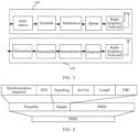
- the physical layer baseband processing module is configured to perform despreading (despreading, that is, an inverse process of spreading), demodulation, and descrambling (descrambling, that is, an inverse process of scrambling) on the radio frequency signal received by the radio frequency front end by using an antenna, to recover the information bit, so as to complete sending and receiving of the information bit, that is, the binary user data.
- the preamble includes a synchronization sequence (synchronization sequence, SYNC) and a start frame delimiter (start frame delimiter, SFD).
- a length of a long preamble is 144 bits, including a 128-bit synchronization sequence located at a front part and a 16-bit SFD located at a rear part.
- a length of a short preamble is 72 bits, including a 56-bit synchronization sequence located at a front part and a 16-bit SFD located at a rear part.
- the SYNC of the long preamble is 128-bit "1" obtained after scrambling (for example, a code of a scrambler used for scrambling may be "1101100"), and the SYNC of the short preamble is 56-bit "0" obtained after scrambling.
- the SYNC is used to wake up a recipient to synchronize with a received signal.
- the SFD is used to notify the recipient that some parameters related to a MAC layer start to be transmitted immediately after the SFD ends.
- a value of the SFD may be, for example, 1111 0011 1010 0000.
- the preamble is usually modulated by using differential binary phase shift keying (differential binary phase shift keying, DBPSK) and transmitted at a rate of 1 M.
- a modulation algorithm of the preamble is fixed.
- a modulation algorithm of the header may be DBPSK or quadrature binary phase shift keying (quadrature binary phase shift keying, QBPSK).
- the PSDU may use another modulation algorithm, for example, DBPSK, QBPSK, complementary code keying (complementary code keying, CCK) (CCK5.5 or CCK11), or the like.
- the header includes physical parameters related to data transmission, and these parameters include signaling (SIGNALING), service (SERVICE), a length (LENGTH) of data to be transmitted, and a 16-bit CRC check code.
- a length of the signaling (SIGNALING) field is 8 bits and the field defines a data transmission rate.
- the field has four values: 0Ah, 14h, 37h, and 6Eh, which respectively specify transmission rates 1 Mbps, 2 Mbps, 5.5 Mbps, and 11 Mbps.
- the recipient adjusts the receiving rate based on the values.
- a length of the service (SERVICE) field is also 8 bits.
- the field specifies a modulation code (CCK or packet binary convolutional coding (packet binary convolutional coding, PBCC)) to be used.
- CCK modulation code
- PBCC packet binary convolutional coding
- a length of the length (LENGTH) field is 16 bits and the field indicates a period of time (a unit thereof is microsecond) that needs to be used to send a subsequent PSDU.
- the 16-bit CRC check code is used to check whether received signaling, service, and length fields are correct.
- the preamble and the header are transmitted at a fixed rate of 1 Mbps.
- the PSDU part may be transmitted at a rate of 1 Mbps (DBPSK modulation), 2 Mbps (DQPSK modulation), 5.5 Mbps (CCK or PBCC), or 11 Mbps (CCK or PBCC).
- IOT Internet of Things
- Wi-Fi-based Internet of Things devices the 802.11b standard has extremely high potential and has the foregoing features.
- a gain of a preamble in the Wi-Fi frame detected by an IoT device based on the 802. 11b standard comes from a spreading gain of the AP.
- the AP uses a conventional Barker (Barker) code whose chip length is 11 to spread a scrambled (scrambling processing) preamble, and a spreading gain is about 10.4 dB.
- Barker Barker
- IoT devices smart home devices such as a refrigerator, an air conditioner, a color TV, a smart curtain, a smart camera, and a smart home
- IoT devices may be distributed in various locations of a home, which imposes a strict requirement on a coverage capability of each device.
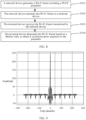
- FIG. 5 shows an amplitude curve of coherence superposition between chips of a Barker code, where a maximum amplitude (10.4 dB) is reached at a position where a chip identifier is 7.
- a maximum peak value of a synchronization sequence of a preamble for spreading based on a Barker chip whose chip length is 11 is limited by the maximum length (11) of coherence superposition between chips of the Barker code, therefore, the maximum peak value of the synchronization sequence may be submerged by noise, and the peak value cannot be detected. Consequently, acquisition (acquisition) cannot be performed on the IoT device. Therefore, the spreading gain cannot meet a wide coverage requirement. As a result, an IoT device in the 802. 11b standard has a weak anti-interference capability and a poor access capability, affecting user experience.
- one or more segments of an extension code provided in this embodiment of this application are mainly used to replace a synchronization sequence of a preamble of a Wi-Fi frame. Because the extension code is generated based on a Barker code, symbols of the extension code are correlated. In this way, in a Wi-Fi frame transmission process, after the synchronization sequence is spread by using the Barker code, chips formed by spreading different symbols included in the extension code are also correlated.
- the network device 101 and the terminal device 103 in this embodiment of this application may also be referred to as communication apparatuses.
- the network device 101 is referred to as a first communication apparatus
- the terminal device 103 is referred to as a second communication apparatus.
- the communication apparatus may be a general-purpose device or a dedicated device. This is not specifically limited in this embodiment of this application.
- FIG. 6 is a schematic diagram of structures of a network device 101 and a terminal device 103 according to an embodiment of this application.
- the memory 302 is configured to store computer-executable instructions for executing the solutions of this application, and the execution is controlled by the processor 301.
- the processor 301 is configured to execute the computer-executable instructions stored in the memory 302, to implement the communication method for a wireless fidelity Wi-Fi system in embodiments of this application.
- the computer-executable instructions in this embodiment of this application may also be referred to as application program code or computer program code. This is not specifically limited in this embodiment of this application.
- the transceiver 303 may use any apparatus such as a transceiver, and is configured to communicate with another device or a communication network.
- the transceiver 303 includes a transmitter (transmitter, Tx) and a receiver (receiver, Rx).
- Tx transmitter
- Rx receiver
- the terminal device 103 receives a Wi-Fi frame by using the receiver.
- the output device 304 communicates with the processor 301, and may display information in a plurality of manners.
- the output device 304 may be a liquid crystal display (liquid crystal display, LCD), a light emitting diode (light emitting diode, LED) display device, a cathode ray tube (cathode ray tube, CRT) display device, or a projector (projector).
- the input device 305 communicates with the processor 301, and may receive an input of a user in a plurality of manners.
- the input device 305 may be a mouse, a keyboard, a touchscreen device, or a sensing device.
- the network device 101 includes at least one processor (an example in which one processor 201 is included is used for description in FIG. 6 ), at least one transceiver (an example in which one transceiver 203 is included is used for description in FIG. 6 ), and at least one network interface (an example in which one network interface 204 is included is used for description in FIG. 6 ).
- the network device 101 may further include at least one memory (an example in which one memory 202 is included is used for description in FIG. 6 ).
- the processor 201, the memory 202, the transceiver 203, and the network interface 204 are connected through a communication line.
- the network interface 204 is configured to connect to a core network device by using a link (for example, an S1 interface), or connect to a network interface of another network device by using a wired or wireless link (for example, an X2 interface) (not shown in FIG. 6 ).
- a link for example, an S1 interface
- a wired or wireless link for example, an X2 interface
- the transceiver 203 may use any apparatus such as a transceiver, and is configured to communicate with another device or a communication network.
- the transceiver 203 includes a transmitter (transmitter, Tx) and a receiver (receiver, Rx).
- Tx transmitter
- Rx receiver
- the network device 101 transmits a Wi-Fi frame by using the transmitter.
- FIG. 7 is a specific structural form of the terminal device 103 according to an embodiment of this application.
- a function of the processor 301 in FIG. 6 may be implemented by a processor 110 in FIG. 7 .
- a function of the transceiver 303 in FIG. 6 may be implemented by using an antenna 1, an antenna 2, a mobile communication module 150, a wireless communication module 160, and the like in FIG. 7 .
- the antenna 1 and the antenna 2 are configured to transmit and receive electromagnetic wave signals.
- Each antenna in the terminal device 103 may be configured to cover one or more communication frequency bands. Different antennas may be further multiplexed, to improve antenna utilization.
- the antenna 1 may be multiplexed as a diversity antenna of a wireless local area network. In some other embodiments, the antenna may be used in combination with a tuning switch.
- the GNSS may include a global positioning system (global positioning system, GPS), a global navigation satellite system (global navigation satellite system, GLONASS), a BeiDou navigation satellite system (BeiDou navigation satellite system, BDS), a quasi-zenith satellite system (quasi-zenith satellite system, QZSS), or a satellite based augmentation system (satellite based augmentation system, SBAS).
- GPS global positioning system
- GLONASS global navigation satellite system
- BeiDou navigation satellite system BeiDou navigation satellite system
- BDS BeiDou navigation satellite system
- QZSS quasi-zenith satellite system
- SBAS satellite based augmentation system
- the following describes, by using an example in which the network device shown in FIG. 1 interacts with any terminal device, a communication method for a wireless fidelity Wi-Fi system according to an embodiment of this application.
- names of messages between network elements, names of parameters in the messages, or the like in the following embodiments of this application are merely examples, and there may be other names in a specific implementation. This is not specifically limited in embodiments of this application.
- the extension code is S, and a construction method of the extension code includes but is not limited to the following method.
- a value of g may be obtained, that is, a symbol position corresponding to the extension code in the chip sequence of c R-ACQ (i) .
- specific steps of constructing the Wi-Fi frame are as follows:
- step S2 scrambling is performed on an all-1 or all-0 synchronization sequence (symbol) whose length is L.
- c ACQ (i) is an original all-1 or all-0 symbol sequence before scrambling, and R(i) is a scrambled sequence generated in S1.
- the terminal device serving as a recipient may perform synchronization position detection based on the sequence C hybrid (i) by using a coherence algorithm, so that coherence combination performance shown in FIG. 9 may be obtained, and a higher coherence peak value may be detected in a synchronization sequence detection process.
- coherence coarse frequency estimation, coherence fine frequency offset estimation, coherence channel estimation, and the like are performed based on a result of the synchronization position detection, parameter estimation performance may also be improved.
- a synchronization sequence of the Wi-Fi frame shown in FIG. 10 includes a plurality of extension codes. For example, five extension codes are placed in the synchronization sequence.
- specific steps of constructing the Wi-Fi frame are as follows:
- step S2 scrambling is performed on an all-1 or all-0 synchronization sequence (symbol) whose length is L.
- c ACQ (i) is an original all-1 or all-0 symbol sequence before scrambling, and R(i) is a scrambled sequence generated in S1.
- the network device serving as the transmitter performs spreading (Barker spreading) based on a protocol requirement in a process of transmitting the Wi-Fi frame in a subsequent step, that is, performs Barker code spreading on the replaced symbol sequence C hybrid (i) , to generate a spreading sequence:
- the terminal device serving as a recipient may perform synchronization position detection based on the sequence C hybrid (i) by using a coherence algorithm, so that coherence combination performance shown in FIG. 9 may be obtained, and a higher coherence peak value may be detected in a synchronization sequence detection process.
- coherence coarse frequency estimation, coherence fine frequency offset estimation, coherence channel estimation, and the like are performed based on a result of the synchronization position detection, parameter estimation performance may also be improved.
- step S2 scrambling is performed on an all-1 or all-0 synchronization sequence (symbol) whose length is L.
- ⁇ c R ⁇ ACQ i R i ⁇ c ACQ i ;
- c ACQ (i) is an original all-1 or all-0 symbol sequence before scrambling, and R(i) is a scrambled sequence generated in S 1.
- detection is performed on C ACQ 0 and C eSFD 0 (or C ACQ 1 and C eSFD 1 ) sequences in the spreading sequence of each group of extension codes in the synchronization sequence, to distinguish the two groups of sequences based on whether the C ACQ 0 and C eSFD 0 (or C ACQ 1 and C eSFD 1 ) sequences are reverse; and whether a group of extension codes is synchronized is identified by using an interval between peak values of the C ACQ 0 and C eSFD 0 sequences, so as to determine a synchronization position based on C ACQ 0 (or C ACQ 1 ) and determine a frame start position based on C eSFD 0 (or C eSFD 1 ) .
- a tail is usually supplemented in a padding (padding) manner.
- the extension header indicates one or more pieces of the following information: a length of the payload, a coding scheme and a modulation scheme of the coding field, and a type of the check field.
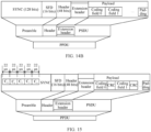
- the eheader may include an elenghth field (12 bits), indicating a length of the payload; an eMOD field (2 bits), indicating a modulation scheme of the payload; a reserved field (reserved, 2 bits); and an eCRC field (8 bits), used to check the eheader.
- the bit in the b3 field may be used to indicate whether the Wi-Fi frame structure provided in this embodiment of this application is used. When the bit is configured as 0, it indicates a conventional 802.11b frame structure, and when the bit is configured as 1, it indicates the Wi-Fi frame structure provided in this embodiment of this application.
- the eheader is designed to send information such as a data length/modulation signaling by using the first 48 bits of the PSDU. Therefore, a polar coding field and a CRC check field that are smaller and formed by using a polar coding scheme may be used for sending, so as to adapt to operation in an extremely low SNR scenario.
- Table 3 provides values of the parameters in the eheader.
- Table 3 Parameter Value (value) eLength 0 to 2 ⁇ 12-1 , indicating a length of the payload, eLength Legacy LENGTH-eSFD LENGTH - eheader LENGTH, and the Legacy LENGTH is a payload length currently specified in the 802.11b protocol.
- eMod Payload modulation scheme indication 0: 512 Kbps
- DBPSK 1 1 Mbps
- DQPSK 2 2.75 Mbps
- CCK55 3 5.5 Mbps
- CCK11 eCoding 0: polar 1: LDPC Reserved
- eCRC 8 bits used to check the eheader
- the extension start frame delimiter SFD may include an eSFD sequence (16 bits) and eCRC (8 bits), which indicate that the eheader is sent subsequently.
- eSFD eSFD sequence
- eCRC eCRC 8 bits
- descrambling may be performed normally, and a descrambler is initialized to prepare for further parsing of the SFD.
- the b3 field of the service (SERVICE) field in the header may be used to indicate whether the Wi-Fi frame structure provided in this embodiment of this application is used.
- the foregoing eSFD and eheader in the MPDU (the MPDU is referred to as a PSDU after entering the PLCP layer) may also be used to indicate that the payload uses the Wi-Fi frame structure provided in this embodiment of this application.
- the eSFD is designed to be sent by using the first 48 bits of the PSDU. Therefore, the eSFD may be sent by using a polar coding field and a CRC check field that are smaller and formed by using a polar coding scheme, to adapt to operation in an extremely low SNR scenario.
- a conventional Wi-Fi frame is detected and the Wi-Fi frame provided in this embodiment of this application is detected, that is, detection of an ACQ (that is, a current synchronization sequence)/SFD/header and detection of an eACQ (that is, a synchronization sequence including an extension code)/eSFD/eheader are simultaneously performed.
- an ACQ that is, a current synchronization sequence
- eACQ that is, a synchronization sequence including an extension code
- the conventional Wi-Fi frame is successfully detected (that is, the ACQ/SFD/header are all successfully detected)
- detection of the conventional Wi-Fi frame is stopped.
- the Wi-Fi frame provided in this embodiment of this application is successfully detected (the eACQ/eSFD/eheader are all successfully detected), data demodulation and decoding of the payload are performed in the manner provided in this embodiment of this application. In addition, when the eheader is successfully detected, detection of the conventional Wi-Fi frame is immediately stopped.
- the data code blocks in the payloads in FIG. 15 and FIG. 16 are described by using an example in which each data code block includes a coding field and a check field, in some examples, the data code blocks in the payloads in FIG. 15 and FIG. 16 may alternatively be in the form shown in FIG. 14B , that is, include only the coding field.
- the network device and the terminal device include corresponding hardware structures and/or software modules for performing the functions.
- a person skilled in the art should be easily aware that, in combination with units and algorithm operations of the examples described in embodiments disclosed in this specification, this application can be implemented by hardware or a combination of hardware and computer software. Whether a function is performed by hardware or hardware driven by computer software depends on particular applications and design constraints of the technical solutions. A person skilled in the art may use different methods to implement the described functions for each particular application, but it should not be considered that the implementation goes beyond the scope of this application.
- functional modules of the network device may be obtained through division based on the foregoing method example.
- the functional modules may be obtained through division corresponding to various functions, or two or more functions may be integrated into one processing module.
- the integrated module may be implemented in a form of hardware, or may be implemented in a form of a software functional module.
- module division is an example, and is merely logical function division. In an actual implementation, another division manner may be used.
- FIG. 17 is a schematic diagram of a structure of a communication apparatus.
- the communication apparatus may be a chip or a system on chip in the foregoing network device, or may be another combined device or component that can implement a function of the foregoing network device.
- the communication apparatus may be configured to perform the function of the network device in the foregoing embodiments.
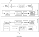
- the communication apparatus shown in FIG. 17 includes a sending unit 1701 and a processing unit 1702.
- the sending unit 1701 is configured to transmit the Wi-Fi frame.
- the synchronization sequence includes: a first group of extension codes, where the first group of extension codes includes a first extension code and a second extension code that is located in first duration after the first extension code; and a second group of extension codes, where the second group of extension codes includes a third extension code and a fourth extension code that is located in second duration after the third extension code; and the second group of extension codes is located after the first group of extension codes, and the first duration is not equal to the second duration.
- the processor is further configured to perform differential coding on the modulated data code blocks, where the modulation scheme includes non-differential modulation.
- the PSDU further includes an extension start frame delimiter SFD located before the extension header.
- the extension code is obtained from a spreading sequence generated by spreading an initial sequence based on the Barker code.
- the communication apparatus is presented in a form that the functional modules are obtained through division in an integrated manner.
- the "module” herein may be an ASIC, a circuit, a processor that executes one or more software or firmware programs, a memory, an integrated logic circuit, and/or another component that can provide the foregoing functions.
- the communication apparatus may be in the form of the network device shown in FIG. 6 .
- functions/implementation processes of the sending unit 1701 and the processing unit 1702 in FIG. 17 may be implemented by the processor 201 in FIG. 6 by invoking the computer-executable instructions stored in the memory 203.
- functions/implementation processes of the processing unit 1702 in FIG. 17 may be implemented by the processor 201 in FIG. 6 by invoking the computer-executable instructions stored in the memory 203
- functions/implementation processes of the sending unit 1701 in FIG. 17 may be implemented by the transmitter in the transceiver 203 in FIG. 6 .
- the communication apparatus provided in this embodiment may perform the foregoing communication method for a wireless fidelity Wi-Fi system. Therefore, for technical effects that can be achieved by the communication apparatus, refer to the foregoing method embodiments. Details are not described herein again.
- functional modules of the terminal device may be obtained through division based on the foregoing method example.
- the functional modules may be obtained through division corresponding to various functions, or two or more functions may be integrated into one processing module.
- the integrated module may be implemented in a form of hardware, or may be implemented in a form of a software functional module.
- module division is an example, and is merely logical function division. In an actual implementation, another division manner may be used.
- FIG. 18 is a schematic diagram of a structure of a communication apparatus.
- the communication apparatus may be a chip or a system on chip in the foregoing terminal device, or may be another combined device or component that can implement a function of the foregoing terminal device.
- the communication apparatus may be configured to perform the function of the network device in the foregoing embodiments.
- a PSDU of the Wi-Fi frame includes an extension header and a payload
- the payload includes a plurality of data code blocks
- each data code block includes a coding field and a check field
- the extension header indicates one or more pieces of the following information: a length of the payload, a coding scheme and a modulation scheme of the coding field, and a type of the check field
- the processing unit 1802 is further configured to: despread the data code blocks based on the Barker code; demodulate the despread data code blocks based on the modulation scheme, where the modulation scheme includes differential modulation; perform rate de-matching on the demodulated data code blocks; and perform channel decoding on data code blocks obtained through the rate de-matching based on the coding scheme.
- the processor is further configured to perform de-differential decoding on the despread data code block, where the modulation scheme includes non-differential modulation.
- the PSDU further includes an extension start frame delimiter SFD located before the extension header.
- the extension code is obtained from a spreading sequence generated by spreading an initial sequence based on the Barker code.
- the communication apparatus is presented in a form that the functional modules are obtained through division in an integrated manner.
- the "module” herein may be an ASIC, a circuit, a processor that executes one or more software or firmware programs, a memory, an integrated logic circuit, and/or another component that can provide the foregoing functions.
- the communication apparatus may be in the form of the terminal device shown in FIG. 6 .
- the processor 201 in FIG. 6 may invoke the computer-executable instructions stored in the memory 203, so that the communication apparatus performs the communication method for a wireless fidelity Wi-Fi system in the foregoing method embodiments.
- functions/implementation processes of the receiving unit 1801 and the processing unit 1802 in FIG. 18 may be implemented by the processor 201 in FIG. 6 by invoking the computer-executable instructions stored in the memory 203.
- functions/implementation processes of the processing unit 1802 in FIG. 18 may be implemented by the processor 201 in FIG. 2 by invoking the computer-executable instructions stored in the memory 203
- functions/implementation processes of the receiving unit 1801 in FIG. 18 may be implemented by the receiver in the transceiver 303 in FIG. 6 .
- FIG. 19 is a schematic diagram of a structure of a communication apparatus.
- the communication apparatus may be a chip or a system on chip in the foregoing network device, or may be another combined device or component that can implement a function of the foregoing network device.
- the communication apparatus may be configured to perform the function of the network device in the foregoing embodiments.
- the processing unit 1902 is further configured to perform differential coding on the data code blocks obtained through the rate matching, where the modulation scheme includes non-differential modulation.
- the extension header further includes a check bit.
- the PSDU further includes an extension start frame delimiter SFD located before the extension header.
- the communication apparatus is presented in a form that the functional modules are obtained through division in an integrated manner.
- the "module” herein may be an ASIC, a circuit, a processor that executes one or more software or firmware programs, a memory, an integrated logic circuit, and/or another component that can provide the foregoing functions.
- the communication apparatus may be in the form of the network device shown in FIG. 6 .
- the communication apparatus provided in this embodiment may perform the foregoing communication method for a wireless fidelity Wi-Fi system. Therefore, for technical effects that can be achieved by the communication apparatus, refer to the foregoing method embodiments. Details are not described herein again.
- functional modules of the terminal device may be obtained through division based on the foregoing method example.
- the functional modules may be obtained through division corresponding to various functions, or two or more functions may be integrated into one processing module.
- the integrated module may be implemented in a form of hardware, or may be implemented in a form of a software functional module.
- module division is an example, and is merely logical function division. In an actual implementation, another division manner may be used.
- FIG. 20 is a schematic diagram of a structure of a communication apparatus.
- the communication apparatus may be a chip or a system on chip in the foregoing terminal device, or may be another combined device or component that can implement a function of the foregoing terminal device.
- the communication apparatus may be configured to perform the function of the network device in the foregoing embodiments.
- the processing unit 2002 is further configured to perform de-differential decoding on the demodulated data code block, and the modulation scheme includes non-differential modulation.
- the extension header further includes a check bit.
- the PSDU further includes an extension start frame delimiter SFD located before the extension header. All related content of the operations in the foregoing method embodiments may be cited in function descriptions of the corresponding functional modules. Details are not described herein again.
- the communication apparatus is presented in a form that the functional modules are obtained through division in an integrated manner.
- the "module” herein may be an ASIC, a circuit, a processor that executes one or more software or firmware programs, a memory, an integrated logic circuit, and/or another component that can provide the foregoing functions.
- the communication apparatus may be in the form of the terminal device shown in FIG. 6 .
- the processor 201 in FIG. 6 may invoke the computer-executable instructions stored in the memory 203, so that the communication apparatus performs the communication method for a wireless fidelity Wi-Fi system in the foregoing method embodiments.
- the communication apparatus provided in this embodiment may perform the foregoing communication method for a wireless fidelity Wi-Fi system. Therefore, for technical effects that can be achieved by the communication apparatus, refer to the foregoing method embodiments. Details are not described herein again.
- the sending unit 1702 and the sending unit 1902 may be transmitters when transmitting information
- the receiving unit 1802 and the receiving unit 2002 may be receivers when receiving information
- a transceiver unit may be a transceiver.
- the transceiver, the transmitter, or the receiver may be a radio frequency circuit.
- the storage unit is configured to store computer instructions.
- the processor is communicatively connected to the memory, and the processor executes the computer instructions stored in the memory, to cause the first communication apparatus and the second communication apparatus to perform the method in the method embodiments.
- the processor may be a general-purpose central processing unit (CPU), a microprocessor, or an application-specific integrated circuit (application-specific integrated circuit, ASIC).
- the storage unit may be a storage unit that is located in the terminal device or the network device and that is located outside the chip, for example, a read-only memory (read-only memory, ROM) or another type of static storage device that can store static information and instructions, or a random access memory (random access memory, RAM).
- ROM read-only memory
- RAM random access memory
- All or some of the foregoing embodiments may be implemented by using software, hardware, firmware, or any combination thereof.
- a software program is used to implement the foregoing embodiments, all or some of the embodiments may be implemented in a form of a computer program product.
- the computer program product includes one or more computer instructions. When the computer program instructions are loaded and executed on a computer, the procedure or functions according to embodiments of this application are all or partially generated.
- the computer may be a general-purpose computer, a dedicated computer, a computer network, or other programmable apparatuses.
- the computer instructions may be stored in a computer-readable storage medium or may be transmitted from one computer-readable storage medium to another computer-readable storage medium.
- the computer instructions may be transmitted from a website, computer, server, or data center to another website, computer, server, or data center in a wired (for example, a coaxial cable, an optical fiber, or a digital subscriber line (digital subscriber line, DSL)) or wireless (for example, infrared, radio, or microwave) manner.
- the computer-readable storage medium may be any usable medium accessible by a computer, or a data storage device, such as a server or a data center, integrating one or more usable media.
- the usable medium may be a magnetic medium (for example, a floppy disk, a hard disk, or a magnetic tape), an optical medium (for example, a DVD), or a semiconductor medium (for example, a solid-state drive (solid-state drive, SSD)).
- the computer may include the apparatus described above.
Landscapes
- Engineering & Computer Science (AREA)
- Computer Networks & Wireless Communication (AREA)
- Signal Processing (AREA)
- Quality & Reliability (AREA)
- Physics & Mathematics (AREA)
- Discrete Mathematics (AREA)
- General Physics & Mathematics (AREA)
- Mathematical Physics (AREA)
- Mobile Radio Communication Systems (AREA)
Applications Claiming Priority (1)
| Application Number | Priority Date | Filing Date | Title |
|---|---|---|---|
| PCT/CN2021/122476 WO2023050435A1 (zh) | 2021-09-30 | 2021-09-30 | 一种用于无线保真Wi-Fi系统的通信方法及装置 |
Publications (2)
| Publication Number | Publication Date |
|---|---|
| EP4401367A1 true EP4401367A1 (de) | 2024-07-17 |
| EP4401367A4 EP4401367A4 (de) | 2024-11-27 |
Family
ID=85781224
Family Applications (1)
| Application Number | Title | Priority Date | Filing Date |
|---|---|---|---|
| EP21959001.5A Pending EP4401367A4 (de) | 2021-09-30 | 2021-09-30 | Kommunikationsverfahren und vorrichtung für wifi-system |
Country Status (4)
| Country | Link |
|---|---|
| US (1) | US20240259124A1 (de) |
| EP (1) | EP4401367A4 (de) |
| CN (1) | CN117957823A (de) |
| WO (1) | WO2023050435A1 (de) |
Families Citing this family (6)
| Publication number | Priority date | Publication date | Assignee | Title |
|---|---|---|---|---|
| CN115473536A (zh) * | 2021-06-11 | 2022-12-13 | 华为技术有限公司 | 一种极化码编码方法、译码方法及装置 |
| CN120416920A (zh) * | 2024-01-31 | 2025-08-01 | 华为技术有限公司 | 通信方法、装置、设备以及存储介质 |
| WO2025184857A1 (zh) * | 2024-03-07 | 2025-09-12 | Oppo广东移动通信有限公司 | 无线通信方法、装置、设备、存储介质及芯片 |
| CN120730456A (zh) * | 2024-03-29 | 2025-09-30 | 华为技术有限公司 | 通信方法及装置 |
| CN119853866A (zh) * | 2024-12-31 | 2025-04-18 | 乐鑫信息科技(上海)股份有限公司 | 无线通信方法、无线发射装置和无线接收装置 |
| CN119854865A (zh) * | 2024-12-31 | 2025-04-18 | 乐鑫信息科技(上海)股份有限公司 | 无线通信方法和装置、计算机可读存储介质和程序产品 |
Family Cites Families (10)
| Publication number | Priority date | Publication date | Assignee | Title |
|---|---|---|---|---|
| US7106803B1 (en) * | 2002-06-26 | 2006-09-12 | Marvell International Ltd. | Phase shift keying wireless communication apparatus and method |
| US8064414B2 (en) * | 2005-12-13 | 2011-11-22 | Qualcomm, Incorporated | Range extension techniques for a wireless local area network |
| US8891592B1 (en) * | 2009-10-16 | 2014-11-18 | Marvell International Ltd. | Control physical layer (PHY) data unit |
| US9832680B2 (en) * | 2015-03-12 | 2017-11-28 | Intel IP Corporation | Dynamic indication map for multicast group and traffic indication |
| CN104901777B (zh) * | 2015-04-17 | 2018-08-21 | 中国工程物理研究院电子工程研究所 | 一种用于太赫兹无线网络的物理层架构系统 |
| US10945219B2 (en) * | 2016-04-15 | 2021-03-09 | Huawei Technologies Co., Ltd. | System and method for a wireless network having multiple station classes |
| CN106209159B (zh) * | 2016-07-18 | 2019-12-13 | 乐鑫信息科技(上海)股份有限公司 | 一种数据包前导序列和包头及其处理方法和数据帧 |
| US10389567B2 (en) * | 2016-11-03 | 2019-08-20 | Samsung Electronics Co., Ltd. | Method and apparatus for synchronization signal design |
| US10298353B2 (en) * | 2017-02-09 | 2019-05-21 | Lg Electronics Inc. | Method and device for receiving uplink signal using differential modulation scheme with interference cancellation and channel estimation |
| US11496924B2 (en) * | 2019-07-02 | 2022-11-08 | Qualcomm Incorporated | Medium access control (MAC) protocol data unit (MPDU) and codeword alignment and validation |
-
2021
- 2021-09-30 EP EP21959001.5A patent/EP4401367A4/de active Pending
- 2021-09-30 WO PCT/CN2021/122476 patent/WO2023050435A1/zh not_active Ceased
- 2021-09-30 CN CN202180102058.5A patent/CN117957823A/zh active Pending
-
2024
- 2024-04-01 US US18/623,763 patent/US20240259124A1/en active Pending
Also Published As
| Publication number | Publication date |
|---|---|
| CN117957823A (zh) | 2024-04-30 |
| WO2023050435A1 (zh) | 2023-04-06 |
| EP4401367A4 (de) | 2024-11-27 |
| US20240259124A1 (en) | 2024-08-01 |
Similar Documents
| Publication | Publication Date | Title |
|---|---|---|
| US20240259124A1 (en) | Communication method for wireless fidelity wi-fi system and apparatus | |
| US11626947B2 (en) | Communication method and communications device | |
| US20250113302A1 (en) | Wireless communication method, terminal device, and network device | |
| US10756802B2 (en) | Communication method and terminal device | |
| US12615101B2 (en) | Communication method for wireless fidelity Wi-Fi system and apparatus | |
| WO2023030019A1 (zh) | 通信方法及装置、计算机可读存储介质 | |
| EP3621275B1 (de) | Sendeverfahren und empfangsverfahren für rundfunksignale, netzwerkvorrichtung und endgerät | |
| US20210378030A1 (en) | Random access method, apparatus, and system | |
| EP3897054B1 (de) | Kommunikationsverfahren, und -vorrichtung | |
| CN103944664B (zh) | 传输信息的方法、基站和用户设备 | |
| EP2991283A1 (de) | Datenübertragungsverfahren und -vorrichtung | |
| US20220224478A1 (en) | Communication method, device, and system | |
| US20200068517A1 (en) | Signal Transmission Method and Apparatus | |
| US20210168699A1 (en) | Wireless communication method, apparatus, and computer-readable storage medium | |
| EP3952538A1 (de) | Kommunikationsverfahren, -vorrichtung und -system | |
| CN111757432B (zh) | 一种唤醒方法以及相关装置 | |
| US20250234294A1 (en) | Methods, apparatus, and systems for low-complexity and low-power wake-up of electronic device | |
| US12294545B2 (en) | Method for receiving and sending reference signal, apparatus, and system | |
| CN117397351B (zh) | 用于无线通信的节点中的方法和装置 | |
| EP3738283A1 (de) | Verschlüsselung von physikalischen kanälen und referenzsignalen in drahtlosen kommunikationsnetzen | |
| EP3902177B1 (de) | Kommunikationsverfahren, -vorrichtung und -system | |
| US11997027B2 (en) | Signal sending method, signal receiving method, and apparatus | |
| CN121795074A (zh) | 通信方法和通信装置 | |
| CN120881761A (zh) | 一种用于无线通信的终端和物联网设备中的方法和装置 | |
| WO2025152835A1 (zh) | 信息传输方法、装置及相关设备 |
Legal Events
| Date | Code | Title | Description |
|---|---|---|---|
| STAA | Information on the status of an ep patent application or granted ep patent |
Free format text: STATUS: THE INTERNATIONAL PUBLICATION HAS BEEN MADE |
|
| PUAI | Public reference made under article 153(3) epc to a published international application that has entered the european phase |
Free format text: ORIGINAL CODE: 0009012 |
|
| STAA | Information on the status of an ep patent application or granted ep patent |
Free format text: STATUS: REQUEST FOR EXAMINATION WAS MADE |
|
| 17P | Request for examination filed |
Effective date: 20240411 |
|
| AK | Designated contracting states |
Kind code of ref document: A1 Designated state(s): AL AT BE BG CH CY CZ DE DK EE ES FI FR GB GR HR HU IE IS IT LI LT LU LV MC MK MT NL NO PL PT RO RS SE SI SK SM TR |
|
| RIC1 | Information provided on ipc code assigned before grant |
Ipc: H04L 1/00 20060101ALI20240704BHEP Ipc: H04J 13/10 20110101ALI20240704BHEP Ipc: H04W 56/00 20090101ALI20240704BHEP Ipc: H04W 84/12 20090101ALI20240704BHEP Ipc: H04B 1/7073 20110101ALI20240704BHEP Ipc: H04L 27/26 20060101AFI20240704BHEP |
|
| A4 | Supplementary search report drawn up and despatched |
Effective date: 20241025 |
|
| RIC1 | Information provided on ipc code assigned before grant |
Ipc: H04L 1/00 20060101ALI20241021BHEP Ipc: H04J 13/10 20110101ALI20241021BHEP Ipc: H04W 56/00 20090101ALI20241021BHEP Ipc: H04W 84/12 20090101ALI20241021BHEP Ipc: H04L 5/00 20060101ALI20241021BHEP Ipc: H04B 1/7073 20110101ALI20241021BHEP Ipc: H04L 27/26 20060101AFI20241021BHEP |
|
| DAV | Request for validation of the european patent (deleted) | ||
| DAX | Request for extension of the european patent (deleted) |