EP4402013B1 - Gestion de charge pour véhicules de travail électriques - Google Patents
Gestion de charge pour véhicules de travail électriques Download PDFInfo
- Publication number
- EP4402013B1 EP4402013B1 EP22843950.1A EP22843950A EP4402013B1 EP 4402013 B1 EP4402013 B1 EP 4402013B1 EP 22843950 A EP22843950 A EP 22843950A EP 4402013 B1 EP4402013 B1 EP 4402013B1
- Authority
- EP
- European Patent Office
- Prior art keywords
- charging
- properties
- vehicle
- electric work
- charging module
- Prior art date
- Legal status (The legal status is an assumption and is not a legal conclusion. Google has not performed a legal analysis and makes no representation as to the accuracy of the status listed.)
- Active
Links
Images

Classifications
-
- B—PERFORMING OPERATIONS; TRANSPORTING
- B60—VEHICLES IN GENERAL
- B60L—PROPULSION OF ELECTRICALLY-PROPELLED VEHICLES; SUPPLYING ELECTRIC POWER FOR AUXILIARY EQUIPMENT OF ELECTRICALLY-PROPELLED VEHICLES; ELECTRODYNAMIC BRAKE SYSTEMS FOR VEHICLES IN GENERAL; MAGNETIC SUSPENSION OR LEVITATION FOR VEHICLES; MONITORING OPERATING VARIABLES OF ELECTRICALLY-PROPELLED VEHICLES; ELECTRIC SAFETY DEVICES FOR ELECTRICALLY-PROPELLED VEHICLES
- B60L53/00—Methods of charging batteries, specially adapted for electric vehicles; Charging stations or on-board charging equipment therefor; Exchange of energy storage elements in electric vehicles
- B60L53/60—Monitoring or controlling charging stations
- B60L53/66—Data transfer between charging stations and vehicles
-
- B—PERFORMING OPERATIONS; TRANSPORTING
- B60—VEHICLES IN GENERAL
- B60L—PROPULSION OF ELECTRICALLY-PROPELLED VEHICLES; SUPPLYING ELECTRIC POWER FOR AUXILIARY EQUIPMENT OF ELECTRICALLY-PROPELLED VEHICLES; ELECTRODYNAMIC BRAKE SYSTEMS FOR VEHICLES IN GENERAL; MAGNETIC SUSPENSION OR LEVITATION FOR VEHICLES; MONITORING OPERATING VARIABLES OF ELECTRICALLY-PROPELLED VEHICLES; ELECTRIC SAFETY DEVICES FOR ELECTRICALLY-PROPELLED VEHICLES
- B60L53/00—Methods of charging batteries, specially adapted for electric vehicles; Charging stations or on-board charging equipment therefor; Exchange of energy storage elements in electric vehicles
- B60L53/10—Methods of charging batteries, specially adapted for electric vehicles; Charging stations or on-board charging equipment therefor; Exchange of energy storage elements in electric vehicles characterised by the energy transfer between the charging station and the vehicle
- B60L53/11—DC charging controlled by the charging station, e.g. mode 4
-
- B—PERFORMING OPERATIONS; TRANSPORTING
- B60—VEHICLES IN GENERAL
- B60L—PROPULSION OF ELECTRICALLY-PROPELLED VEHICLES; SUPPLYING ELECTRIC POWER FOR AUXILIARY EQUIPMENT OF ELECTRICALLY-PROPELLED VEHICLES; ELECTRODYNAMIC BRAKE SYSTEMS FOR VEHICLES IN GENERAL; MAGNETIC SUSPENSION OR LEVITATION FOR VEHICLES; MONITORING OPERATING VARIABLES OF ELECTRICALLY-PROPELLED VEHICLES; ELECTRIC SAFETY DEVICES FOR ELECTRICALLY-PROPELLED VEHICLES
- B60L53/00—Methods of charging batteries, specially adapted for electric vehicles; Charging stations or on-board charging equipment therefor; Exchange of energy storage elements in electric vehicles
- B60L53/10—Methods of charging batteries, specially adapted for electric vehicles; Charging stations or on-board charging equipment therefor; Exchange of energy storage elements in electric vehicles characterised by the energy transfer between the charging station and the vehicle
- B60L53/12—Inductive energy transfer
- B60L53/126—Methods for pairing a vehicle and a charging station, e.g. establishing a one-to-one relation between a wireless power transmitter and a wireless power receiver
-
- B—PERFORMING OPERATIONS; TRANSPORTING
- B60—VEHICLES IN GENERAL
- B60L—PROPULSION OF ELECTRICALLY-PROPELLED VEHICLES; SUPPLYING ELECTRIC POWER FOR AUXILIARY EQUIPMENT OF ELECTRICALLY-PROPELLED VEHICLES; ELECTRODYNAMIC BRAKE SYSTEMS FOR VEHICLES IN GENERAL; MAGNETIC SUSPENSION OR LEVITATION FOR VEHICLES; MONITORING OPERATING VARIABLES OF ELECTRICALLY-PROPELLED VEHICLES; ELECTRIC SAFETY DEVICES FOR ELECTRICALLY-PROPELLED VEHICLES
- B60L53/00—Methods of charging batteries, specially adapted for electric vehicles; Charging stations or on-board charging equipment therefor; Exchange of energy storage elements in electric vehicles
- B60L53/30—Constructional details of charging stations
- B60L53/305—Communication interfaces
-
- B—PERFORMING OPERATIONS; TRANSPORTING
- B60—VEHICLES IN GENERAL
- B60L—PROPULSION OF ELECTRICALLY-PROPELLED VEHICLES; SUPPLYING ELECTRIC POWER FOR AUXILIARY EQUIPMENT OF ELECTRICALLY-PROPELLED VEHICLES; ELECTRODYNAMIC BRAKE SYSTEMS FOR VEHICLES IN GENERAL; MAGNETIC SUSPENSION OR LEVITATION FOR VEHICLES; MONITORING OPERATING VARIABLES OF ELECTRICALLY-PROPELLED VEHICLES; ELECTRIC SAFETY DEVICES FOR ELECTRICALLY-PROPELLED VEHICLES
- B60L53/00—Methods of charging batteries, specially adapted for electric vehicles; Charging stations or on-board charging equipment therefor; Exchange of energy storage elements in electric vehicles
- B60L53/60—Monitoring or controlling charging stations
- B60L53/62—Monitoring or controlling charging stations in response to charging parameters, e.g. current, voltage or electrical charge
-
- B—PERFORMING OPERATIONS; TRANSPORTING
- B60—VEHICLES IN GENERAL
- B60L—PROPULSION OF ELECTRICALLY-PROPELLED VEHICLES; SUPPLYING ELECTRIC POWER FOR AUXILIARY EQUIPMENT OF ELECTRICALLY-PROPELLED VEHICLES; ELECTRODYNAMIC BRAKE SYSTEMS FOR VEHICLES IN GENERAL; MAGNETIC SUSPENSION OR LEVITATION FOR VEHICLES; MONITORING OPERATING VARIABLES OF ELECTRICALLY-PROPELLED VEHICLES; ELECTRIC SAFETY DEVICES FOR ELECTRICALLY-PROPELLED VEHICLES
- B60L53/00—Methods of charging batteries, specially adapted for electric vehicles; Charging stations or on-board charging equipment therefor; Exchange of energy storage elements in electric vehicles
- B60L53/60—Monitoring or controlling charging stations
- B60L53/67—Controlling two or more charging stations
-
- B—PERFORMING OPERATIONS; TRANSPORTING
- B60—VEHICLES IN GENERAL
- B60L—PROPULSION OF ELECTRICALLY-PROPELLED VEHICLES; SUPPLYING ELECTRIC POWER FOR AUXILIARY EQUIPMENT OF ELECTRICALLY-PROPELLED VEHICLES; ELECTRODYNAMIC BRAKE SYSTEMS FOR VEHICLES IN GENERAL; MAGNETIC SUSPENSION OR LEVITATION FOR VEHICLES; MONITORING OPERATING VARIABLES OF ELECTRICALLY-PROPELLED VEHICLES; ELECTRIC SAFETY DEVICES FOR ELECTRICALLY-PROPELLED VEHICLES
- B60L58/00—Methods or circuit arrangements for monitoring or controlling batteries or fuel cells, specially adapted for electric vehicles
- B60L58/10—Methods or circuit arrangements for monitoring or controlling batteries or fuel cells, specially adapted for electric vehicles for monitoring or controlling batteries
- B60L58/12—Methods or circuit arrangements for monitoring or controlling batteries or fuel cells, specially adapted for electric vehicles for monitoring or controlling batteries responding to state of charge [SoC]
-
- B—PERFORMING OPERATIONS; TRANSPORTING
- B60—VEHICLES IN GENERAL
- B60L—PROPULSION OF ELECTRICALLY-PROPELLED VEHICLES; SUPPLYING ELECTRIC POWER FOR AUXILIARY EQUIPMENT OF ELECTRICALLY-PROPELLED VEHICLES; ELECTRODYNAMIC BRAKE SYSTEMS FOR VEHICLES IN GENERAL; MAGNETIC SUSPENSION OR LEVITATION FOR VEHICLES; MONITORING OPERATING VARIABLES OF ELECTRICALLY-PROPELLED VEHICLES; ELECTRIC SAFETY DEVICES FOR ELECTRICALLY-PROPELLED VEHICLES
- B60L2200/00—Type of vehicles
- B60L2200/40—Working vehicles
-
- B—PERFORMING OPERATIONS; TRANSPORTING
- B60—VEHICLES IN GENERAL
- B60L—PROPULSION OF ELECTRICALLY-PROPELLED VEHICLES; SUPPLYING ELECTRIC POWER FOR AUXILIARY EQUIPMENT OF ELECTRICALLY-PROPELLED VEHICLES; ELECTRODYNAMIC BRAKE SYSTEMS FOR VEHICLES IN GENERAL; MAGNETIC SUSPENSION OR LEVITATION FOR VEHICLES; MONITORING OPERATING VARIABLES OF ELECTRICALLY-PROPELLED VEHICLES; ELECTRIC SAFETY DEVICES FOR ELECTRICALLY-PROPELLED VEHICLES
- B60L2240/00—Control parameters of input or output; Target parameters
- B60L2240/70—Interactions with external data bases, e.g. traffic centres
-
- B—PERFORMING OPERATIONS; TRANSPORTING
- B60—VEHICLES IN GENERAL
- B60L—PROPULSION OF ELECTRICALLY-PROPELLED VEHICLES; SUPPLYING ELECTRIC POWER FOR AUXILIARY EQUIPMENT OF ELECTRICALLY-PROPELLED VEHICLES; ELECTRODYNAMIC BRAKE SYSTEMS FOR VEHICLES IN GENERAL; MAGNETIC SUSPENSION OR LEVITATION FOR VEHICLES; MONITORING OPERATING VARIABLES OF ELECTRICALLY-PROPELLED VEHICLES; ELECTRIC SAFETY DEVICES FOR ELECTRICALLY-PROPELLED VEHICLES
- B60L2240/00—Control parameters of input or output; Target parameters
- B60L2240/80—Time limits
-
- B—PERFORMING OPERATIONS; TRANSPORTING
- B60—VEHICLES IN GENERAL
- B60L—PROPULSION OF ELECTRICALLY-PROPELLED VEHICLES; SUPPLYING ELECTRIC POWER FOR AUXILIARY EQUIPMENT OF ELECTRICALLY-PROPELLED VEHICLES; ELECTRODYNAMIC BRAKE SYSTEMS FOR VEHICLES IN GENERAL; MAGNETIC SUSPENSION OR LEVITATION FOR VEHICLES; MONITORING OPERATING VARIABLES OF ELECTRICALLY-PROPELLED VEHICLES; ELECTRIC SAFETY DEVICES FOR ELECTRICALLY-PROPELLED VEHICLES
- B60L2260/00—Operating Modes
- B60L2260/40—Control modes
- B60L2260/44—Control modes by parameter estimation
-
- B—PERFORMING OPERATIONS; TRANSPORTING
- B60—VEHICLES IN GENERAL
- B60L—PROPULSION OF ELECTRICALLY-PROPELLED VEHICLES; SUPPLYING ELECTRIC POWER FOR AUXILIARY EQUIPMENT OF ELECTRICALLY-PROPELLED VEHICLES; ELECTRODYNAMIC BRAKE SYSTEMS FOR VEHICLES IN GENERAL; MAGNETIC SUSPENSION OR LEVITATION FOR VEHICLES; MONITORING OPERATING VARIABLES OF ELECTRICALLY-PROPELLED VEHICLES; ELECTRIC SAFETY DEVICES FOR ELECTRICALLY-PROPELLED VEHICLES
- B60L2260/00—Operating Modes
- B60L2260/40—Control modes
- B60L2260/50—Control modes by future state prediction
- B60L2260/58—Departure time prediction
-
- Y—GENERAL TAGGING OF NEW TECHNOLOGICAL DEVELOPMENTS; GENERAL TAGGING OF CROSS-SECTIONAL TECHNOLOGIES SPANNING OVER SEVERAL SECTIONS OF THE IPC; TECHNICAL SUBJECTS COVERED BY FORMER USPC CROSS-REFERENCE ART COLLECTIONS [XRACs] AND DIGESTS
- Y02—TECHNOLOGIES OR APPLICATIONS FOR MITIGATION OR ADAPTATION AGAINST CLIMATE CHANGE
- Y02T—CLIMATE CHANGE MITIGATION TECHNOLOGIES RELATED TO TRANSPORTATION
- Y02T10/00—Road transport of goods or passengers
- Y02T10/60—Other road transportation technologies with climate change mitigation effect
- Y02T10/70—Energy storage systems for electromobility, e.g. batteries
-
- Y—GENERAL TAGGING OF NEW TECHNOLOGICAL DEVELOPMENTS; GENERAL TAGGING OF CROSS-SECTIONAL TECHNOLOGIES SPANNING OVER SEVERAL SECTIONS OF THE IPC; TECHNICAL SUBJECTS COVERED BY FORMER USPC CROSS-REFERENCE ART COLLECTIONS [XRACs] AND DIGESTS
- Y02—TECHNOLOGIES OR APPLICATIONS FOR MITIGATION OR ADAPTATION AGAINST CLIMATE CHANGE
- Y02T—CLIMATE CHANGE MITIGATION TECHNOLOGIES RELATED TO TRANSPORTATION
- Y02T10/00—Road transport of goods or passengers
- Y02T10/60—Other road transportation technologies with climate change mitigation effect
- Y02T10/7072—Electromobility specific charging systems or methods for batteries, ultracapacitors, supercapacitors or double-layer capacitors
-
- Y—GENERAL TAGGING OF NEW TECHNOLOGICAL DEVELOPMENTS; GENERAL TAGGING OF CROSS-SECTIONAL TECHNOLOGIES SPANNING OVER SEVERAL SECTIONS OF THE IPC; TECHNICAL SUBJECTS COVERED BY FORMER USPC CROSS-REFERENCE ART COLLECTIONS [XRACs] AND DIGESTS
- Y02—TECHNOLOGIES OR APPLICATIONS FOR MITIGATION OR ADAPTATION AGAINST CLIMATE CHANGE
- Y02T—CLIMATE CHANGE MITIGATION TECHNOLOGIES RELATED TO TRANSPORTATION
- Y02T90/00—Enabling technologies or technologies with a potential or indirect contribution to GHG emissions mitigation
- Y02T90/10—Technologies relating to charging of electric vehicles
- Y02T90/12—Electric charging stations
-
- Y—GENERAL TAGGING OF NEW TECHNOLOGICAL DEVELOPMENTS; GENERAL TAGGING OF CROSS-SECTIONAL TECHNOLOGIES SPANNING OVER SEVERAL SECTIONS OF THE IPC; TECHNICAL SUBJECTS COVERED BY FORMER USPC CROSS-REFERENCE ART COLLECTIONS [XRACs] AND DIGESTS
- Y02—TECHNOLOGIES OR APPLICATIONS FOR MITIGATION OR ADAPTATION AGAINST CLIMATE CHANGE
- Y02T—CLIMATE CHANGE MITIGATION TECHNOLOGIES RELATED TO TRANSPORTATION
- Y02T90/00—Enabling technologies or technologies with a potential or indirect contribution to GHG emissions mitigation
- Y02T90/10—Technologies relating to charging of electric vehicles
- Y02T90/16—Information or communication technologies improving the operation of electric vehicles
Definitions
- the invention relates to the field of electric work vehicles.
- the charging points may be at the same location or at different locations.
- An operator of an electric work vehicle may not know the location of the charging points, particularly if the charging point locations vary between worksites or if the charging points are mobile. The operator may waste time and charge travelling to look for a charging point. An operator of an electric work vehicles may travel to a charging point in order to charge without knowledge of any properties of the charging point, and so risk not being able to charge. For example, the charging point may be in use by another vehicle, low on power or charge, out of order, the wrong type of charging point, or otherwise unusable. In the event that an electric work vehicle cannot charge at the charging point, the electric work vehicle may be required to wait or to travel to a different charging point.
- EP 3726455 A2 describes a method for forecasting availability of at least one charging station for an electric vehicle.
- a specific charging requirement is determined for a plurality of electric vehicles.
- Each of the electric vehicles issues a request regarding the availability of at least one charging station depending on the specific charging requirement.
- a real demand for a charging process is estimated for the at least one charging station based on the requests of the electric vehicles, and from this a first probability for the availability of the at least one charging station at a future point in time is determined.
- US 2019/193573 A1 describes a travelling energy distribution system that includes a plurality of supply facilities each of which is able to supply travelling energy to a vehicle.
- the system includes an information acquisition unit configured to acquire, from a vehicle, vehicle information relevant to an amount of travelling energy remaining in the vehicle and acquire, from each of the plurality of supply facilities, supply facility information relevant to an amount of travelling energy that can be supplied from that supply facility.
- the system includes a determination unit configured to determine a transfer source supply facility and a transfer destination supply facility for travelling energy to be transferred from among the plurality of supply facilities and determine an amount of the travelling energy to be transferred based on the vehicle information and the supply facility information acquired by the information acquisition unit.
- WO 2014/033944 A1 describes a charging support system and method for an electric vehicle.
- a control center detects a specific electric vehicle that needs to be charged in order to reach a destination from a current location of the electric vehicle on the basis of prescribed electric vehicle information obtained from each electric vehicle, detects a specific charging station that is available for the specific electric vehicle on the basis of information on the specific charging station among multiple charging stations and the electric vehicle information on the specific electric vehicle, detects a specific route for navigating the specific electric vehicle to the specific charging station, and transmits specific navigation information, which includes the specific route, to the specific electric vehicle.
- US 2021/008997 A1 describes a system and method for charging machines.
- the method includes causing, with a controller, operation of a first compaction machine at a worksite based at least in part on a worksite plan.
- the method also includes determining, with the controller, a return path extending from a current location of the first machine to a charging zone located at the worksite, and determining, with the controller, a return power required for the first machine to traverse the return path.
- the method further includes causing, with the controller, the first machine to traverse the return path, from the current location to the charging zone, based on at least one of the return power and an amount of available power stored in an energy storage device of the first machine.
- WO 2022/219362 A1 describes a system and method for charging electric vehicles (EVs).
- a computer-based system is described for managing energy supply and demand at an EV charging facility, which charging facility may comprise a plurality of EV charge points.
- the system comprises a data capture module configured to receive data representative of a number of EVs, including EV charge status and EV location.
- An energy supply and demand processing unit determines a subgroup of the EVs and corresponding prospective customers based on said received data.
- An EV charge offer module is configured to issue EV charge offers for the benefit of the EV customers in the subgroup. These EV charge offers each include at least a proposed EV charge time and may also include an allocated EV charge point.
- KR 2013 0094919 A describes a reservation-based charging service for electric vehicles.
- An electric vehicle transmits a reservation request message including the information on a current position and a battery to a reservation charge server and receives the information of a charging station from the reservation charge server.
- the electric vehicle transmits a reservation acceptance message to the reservation request server.
- the charging stations transmits the information of the charging station including the position of the charging station, sale prices, a charging schedule, and power situation of the charging station to the reservation charge server.
- the charging stations receive the reservation acceptance message from the reservation charge server and add the electric vehicle for reservation in the charge schedule.
- the reservation charge server receives and stores the information of the charging station from the charging station, receives the reservation request message from the electric vehicle, compares and analyzes the power situation of the charging station and a battery property of the electric vehicle, removes the charging station which is unsuitable for conditions, arranges the rest of the charging station by arranging the same by the distance, the sale price, and expected waiting time for charging in an ascending order, searches the optimal charging station, transmits the information of the searched charging station to the electric vehicle, and transmits the reservation acceptance message to the charging station by receiving the reservation acceptance message from the electric vehicle.
- CN 110435474 A describes a charging method applied to a server.
- the server collects position information and working state information of multiple battery charging stations.
- the charging method comprises the steps of receiving a charging request of an electric vehicle; obtaining position information, power capacity information and running path information of the electric vehicle; selecting one target battery charging station from multiple target battery charging stations according to position information and working state information of the multiple target battery charging stations in a surrounding area of the electric vehicle and the position information, the power capacity information and the running path information of the electric vehicle; and transmitting the position information of the target battery charging station to the electric vehicle so that the electric vehicle runs to the target battery charging station to execute charging operation.
- US 2021/065073 A1 describes a system and method for presenting electric vehicle charging options.
- the system and method include determining at least one charging station that is within a remaining distance that the electric vehicle is capable of travelling based on the current geo-location of the electric vehicle and the current state of charge of the battery of the electric vehicle.
- the system and method further include presenting a charging station map user interface that pin points the current geo-location of the electric vehicle and the at least one charging station.
- One or more of the charging stations are presented with labels.
- the system and method further include reserving the at least one charging station for charging the electric vehicle by selecting one or more particular user interface selectable geo-locations that are presented on the charging station map user interface.
- WO 2013/032519 A1 describes a battery charging station and method of use.
- the charging station includes a plurality of charge ports and a plurality of power stages where each stage provides a portion of the station's maximum available charging power.
- a switching system couples the output of the power stages to the charging ports based on charging station and vehicle conditions as well as a predefined set of power distribution rules.
- Current charging station and vehicle conditions may include vehicle arrival time, usage fees, vehicle/customer priority information, SOC, and intended departure time.
- the method includes the steps of monitoring and determining battery charging station conditions, determining power distribution for the battery charging station and the charging ports in response to the current charging conditions and in accordance with a predefined set of power distribution rules, and coupling the power stages to the charging ports in accordance with the power distribution.
- a method of charging management for electric work vehicles according to the invention and a
- Electric work vehicles commonly operate off road at work sites, for example on construction sites or at mining sites.
- the plurality of electric work vehicles at the work site will need to be charged.
- the electric work vehicle and charging module need to communicate. For example, communicating a status of a charging module to an electric work vehicle prevents the electric work vehicle wasting time and charge travelling to a charging module that is in use by another electric work vehicle, that is low on power or charge, or that is otherwise unusable.
- Communicating the location of the charging modules which may differ between work sites or even over time in the same work site, means that the electric work vehicles can travel efficiently to the charging module.
- communicating properties of the electric work vehicles to the charging modules allows efficient charging of the electric work vehicles, for example by ensuring that the electric work vehicle travels to a charging module that can provide at least the amount of charge required by the electric work vehicle.
- Recharging an electric work vehicle can be time consuming, and queues may form at charging modules. Communication between the charging module and the electric work vehicle allows the electric work vehicle to travel to a charging module that is or that soon will be available.
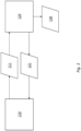
- a method of charging management for electric work vehicles comprises communicating charger properties 111 from a charging module 110 to an electric work vehicle 120 and communicating vehicle properties 121 from the electric work vehicle 120 to the charging module 110.
- Charging information 130 is provided to an operator.
- the charging information 130 is based on the charger properties 111 and the vehicle properties 121.
- the charger properties 111 comprise a location of the charging module 110 and an availability of the charging module 110.
- the vehicle properties comprise a current state of charge of a battery of the electric work vehicle and a capacity of the battery of the electric work vehicle.
- Communicating charger properties 111 to the electric work vehicle 120 and communicating vehicle properties 121 to the charging module 110 may occur at the same time, or sequentially in either order.
- the charger properties 111 and vehicle properties 121 may be communicated continuously or at regular intervals.
- the charger properties 111 and vehicle properties 121 may alternatively be communicated on demand, for example in response to a request by an operator.
- the charger properties 111 and vehicle properties 121 may be communicated directly between the charging module 110 and the electric work vehicle 120.
- the charger properties 111 and vehicle properties 121 may be communicated between the charging module 110 and the electric work vehicle 120 via a central controller 200.
- the central controller may provide the charging information 130.
- the charging module 110 and the electric work vehicle 120 may each comprise a telematics module.
- the telematics modules may be configured to send and receive the charger properties 111 and the vehicle properties 121.
- the electric work vehicle 120 may communicate vehicle properties 121 to and receive charger properties 11 from more than one charging module 110.
- the charging module 110 may communicate charger properties 111 to and receive vehicle properties 121 from more than one electric work vehicle 120.
- the charging module may comprise a mains supply, or may not be connected to the mains supply.
- the charging module may comprise a power pack.
- the charger may comprise a generator.
- the charger properties 111 may further include a health status of the charger. For example, whether the charger is working, and whether there is any damage to the charger or limited capability of the charger.
- the charger properties 111 may further comprise a charging capacity of the charger. For example, in the event that the charger is not connected to the mains supply, it may have a limited amount of charge available.
- the charging capacity may comprise a state of charge of power pack. In an embodiment, the charging capacity may comprise either an indication that the charger has sufficient charge to fully charge the battery, or an indication of the predicted state of charge of the battery after fully draining the charger.
- the charger properties 111 may further comprise a charging rate of the charger, and a charger connection type (such as DC, AC, three phase).
- the charger properties 111 comprise an availability of the charging module 110.
- the availability of the charging module 110 may comprise an indication of whether the charger is in use and a reservation status of the charger. For example, the charger may be currently in use, currently free, reserved for use at a certain time by another vehicle, or unreserved. In an event that the charger is in use, the availability of the charging module 110 may further comprise a predicted charging end time at which the charger will be available. Similarly, in an event that the charger is reserved, the availability of the charging module 110 may further comprise a period when the charger is free prior to the reservation and/or a predicted end time of the reservation.
- the predicted charging end time may be communicated from the charger to the electric work vehicle 120.
- the predicted charging end time may be calculated by the electric work vehicle 120 or central controller based on a current state of charge of the battery being charged, a target state of charge of the battery being charged, and a charging rate of the charger.
- the charger properties 111 may further comprise a predicted state of charge of the charger at the predicted charging end time.
- the charger may comprise a DC charger and the charger properties may further comprise a DC voltage of the charger.
- the vehicle properties 121 may further comprise a predicted time before charging is required.
- the predicted time may be based on at least one of a current state of charge, a discharge rate, and a distance from the charger.
- the discharge rate may be based on a current discharge rate.
- the discharge rate may be based on data from previous discharging of the battery, for example data comprising discharge rates at different states of charge, or discharge rates for the operator, or discharge rates for performing various tasks with the vehicle.
- the distance from the charger may be used to calculate the state of charge required to travel to the charger, and therefore the minimum state of charge that the vehicle can reach before needing to travel to the charger.
- the vehicle properties 121 may further comprise an available time period for charging.
- the available time may be based on a return-to-work time for the electric work vehicle 120.
- the electric work vehicle 120 may be charged at the end of an operator's shift, and the return-to-work time may comprise the beginning of the next shift for the electric work vehicle 120 (for the same or a different operator). Otherwise, an available time period may comprise a lunch break of the operator, a weekend, a closed period of the worksite, or other time period.
- the vehicle properties 121 may further comprise a target state of charge for charging the battery.
- the target state of charge may be to fully charge the battery to a 100% state of charge.
- the target state of charge may comprise a state of charge that has been determined to be appropriate to maintain good battery health.
- the target state of charge may be the state of charge required to complete the next task or the next shift.
- the vehicle properties 121 may further comprise at least one of a battery voltage, a maximum charge rate of the battery, a state of health of the battery, and a temperature of the battery.
- the charging module 110 may comprise a geofence.
- the geofence may define a perimeter around the charging module 110, for example based on a radius from the charging module 110.
- a speed of the electric work vehicle 120 may be limited to below a threshold speed, and/or the electric work vehicle 120 may be limited in the tasks it can perform.
- the charger properties may further comprise the geofence and any limitations on the electric work vehicle 120 that occur within the geofence.
- the charging information 130 provided to the operator may comprise information to allow the operator to make an informed charging decision.
- the charging information 130 may comprise the predicted time before charging is required and distances to available charging modules.
- the charging information 130 provided to the operator may comprise a result of a charging decision made by a controller (either the central controller or a controller of the electric work vehicle). For example, the controller may decide which charging module 110 the electric work vehicle 120 should travel to, and when the electric work vehicle 120 should travel to or arrive at the charging module.
- the method may further comprise making a reservation of the charging module 110.
- the reservation may be made by the operator based on the charging information 130.
- the reservation may be suggested to the operator by a controller based on a charging decision made by the controller, and the operator may confirm or reject the reservation.
- the reservation may be made by a controller based on a charging decision made by the controller, without input from the operator.
- the method of charging management may comprise communicating charger properties 111 from a plurality of charging modules 110 to an electric work vehicle 120.
- the charging information 130 may be based on the charger properties 111 for the plurality of charging modules 110, such that the charging decision (made by the operator or a controller) comprises a decision of whether or when to charge the electric work vehicle, and which charging module to use.
- the charging information 130 may be provided to the operator via a display in the electric work vehicle cab, via a smartphone, or by other means.
- a charging management device for electric work vehicles.
- the charging management device is configured to communicate charger properties 111 from a charging module 110 to an electric work vehicle and communicate vehicle properties 121 from the electric work vehicle 120 to the charging module 110.
- the charging management device is further configured to provide charging information 130 to an operator, wherein the charging information 130 is based on the charger properties 111 and the vehicle properties 121.
- the charger properties 111 comprise location of the charging module 110 and an availability of the charging module 110.
- the vehicle properties 121 comprise a current state of charge of a battery of the electric work vehicle 120 and a capacity of the battery of the electric work vehicle 110.
- the charging management device may be configured to carry out any of the methods described above.
- the charging management device may comprise a controller (either a central controller or a controller on the electric work vehicle 120).
- the charging management device may comprise a telematics device on the charging module 110, and a telematics device on the electric work vehicle 120.
Landscapes
- Engineering & Computer Science (AREA)
- Power Engineering (AREA)
- Transportation (AREA)
- Mechanical Engineering (AREA)
- Life Sciences & Earth Sciences (AREA)
- Sustainable Development (AREA)
- Sustainable Energy (AREA)
- Computer Networks & Wireless Communication (AREA)
- Charge And Discharge Circuits For Batteries Or The Like (AREA)
- Electric Propulsion And Braking For Vehicles (AREA)
Claims (15)
- Procédé de gestion de charge pour les véhicules de travail électriques, le procédé comprenant : la communication de propriétés de chargeur (111) d'un module de charge (110) à un véhicule de travail électrique (120) ;la communication de propriétés de véhicule (121) du véhicule de travail électrique (120) au module de charge (110) ; et la fourniture d'informations de charge (130) à un opérateur, dans lequel les informations de charge (130) sont basées sur les propriétés de chargeur (111) et les propriétés de véhicule (121) ;dans lequel les propriétés de chargeur (111) comprennent :une position du module de charge (110) ; etune disponibilité du module de charge (110) ; etdans lequel les propriétés de véhicule (121) comprennent :un état de charge actuel d'une batterie du véhicule de travail électrique (120) ;une capacité de la batterie du véhicule de travail électrique (120) ; etune période de temps disponible pour la charge en fonction d'une heure de retour au travail du véhicule de travail électrique (120) ;caractérisé en ce que les propriétés de véhicule comprennent en outre :
un moment prédit avant que la charge ne soit requise, dans lequel le moment est basé sur les données d'une décharge précédente de la batterie du véhicule de travail électrique (120) comprenant au moins l'un parmi :des régimes de décharge à différents états de charge ;des régimes de décharge pour l'opérateur ; etdes régimes de décharge pour l'exécution de diverses tâches au moyen du véhicule de travail électrique (120). - Procédé selon la revendication 1, dans lequel les propriétés de chargeur (111) comprennent en outre au moins l'un parmi :un état de santé du module de charge (110) ;une capacité de charge du module de charge (110) ;un régime de charge ; etun type de connexion du module de charge.
- Procédé selon la revendication 1 ou 2, dans lequel la disponibilité du module de charge comprend au moins l'un parmi :
une indication du fait de savoir si le module de charge (110) est en cours d'utilisation ; et un état de réservation du module de charge (110). - Procédé selon la revendication 3 dans lequel, dans le cas où le module de charge (110) est en cours d'utilisation, la disponibilité du module de charge (110) comprend un temps de fin de charge prédit.
- Procédé selon la revendication 4, dans lequel le temps de fin de charge prédit est soit : communiqué par le module de charge (110) au véhicule de travail électrique (120) ; soit calculé par le véhicule de travail électrique (120) en fonction d'un état de charge actuel de la batterie en cours de charge, d'un état de charge cible de la batterie en cours de charge et d'un régime de charge du module de charge (110).
- Procédé selon l'une quelconque des revendications précédentes, dans lequel le module de charge (110) comprend un chargeur CC et dans lequel les propriétés de chargeur comprennent en outre une tension CC.
- Procédé selon l'une quelconque des revendications précédentes, dans lequel les propriétés de véhicule (121) comprennent en outre au moins l'un parmi :un moment prédit avant que la charge ne soit requise ;une période de temps disponible pour la charge ; et un état de charge cible pour la charge.
- Procédé selon l'une quelconque des revendications précédentes, dans lequel les propriétés de véhicule (121) comprennent en outre au moins l'un parmi :une tension de la batterie ;un régime de charge maximal de la batterie ;un état de santé de la batterie ; et une température de la batterie.
- Procédé selon l'une quelconque des revendications précédentes, dans lequel la communication des propriétés de chargeur (111) et la communication des propriétés de véhicule (121) s'effectuent par le biais d'un dispositif de commande distinct.
- Procédé selon l'une quelconque des revendications précédentes, dans lequel le module de charge (110) et le véhicule de travail électrique (120) comprennent chacun un module télématique.
- Procédé selon l'une quelconque des revendications précédentes, dans lequel les propriétés de chargeur (111) comprennent en outre un rayon autour du module de charge (110), rayon dans lequel la vitesse du véhicule de travail électrique (120) est limitée à une valeur en dessous d'une vitesse seuil.
- Procédé selon l'une quelconque des revendications précédentes, dans lequel les informations de charge (111) comprennent un résultat d'une décision de charge prise par un dispositif de commande.
- Procédé selon l'une quelconque des revendications précédentes, comprenant en outre la réservation du module de charge (110).
- Dispositif de gestion de charge pour les véhicules de travail électriques, le dispositif de gestion de charge étant conçu pour :communiquer les propriétés de chargeur (111) d'un module de charge (110) à un véhicule de travail électrique (120) ;communiquer les propriétés de véhicule (121) du véhicule de travail électrique (120) au module de charge (110) ; etfournir des informations de charge (130) à un opérateur, dans lequel les informations de charge (130) sont basées sur les propriétés de chargeur (111) et les propriétés de véhicule (121) ;dans lequel les propriétés de chargeur (111) comprennent :une position du module de charge (110) ; etune disponibilité du module de charge (120) ; etdans lequel les propriétés de véhicule (121) comprennent :un état de charge actuel d'une batterie du véhicule de travail électrique (120) ;une capacité de la batterie du véhicule de travail électrique (120) ; etune période de temps disponible pour la charge en fonction d'une heure de retour au travail du véhicule de travail électrique (120) ;caractérisé en ce que les propriétés de véhicule comprennent en outre :
un moment prédit avant que la charge ne soit requise, dans lequel le moment est basé sur les données d'une décharge précédente de la batterie du véhicule de travail électrique (120) comprenant au moins l'un parmi :des régimes de décharge à différents états de charge ;des régimes de décharge pour l'opérateur ; etdes régimes de décharge pour l'exécution de diverses tâches au moyen du véhicule de travail électrique (120). - Dispositif de gestion de charge selon la revendication 14, dans lequel les propriétés de chargeur (111) comprennent en outre au moins l'un parmi :un état de santé du module de charge (110) ;une capacité de charge du module de charge (110) ;un régime de charge ; etun type de connexion du module de charge.
Applications Claiming Priority (2)
| Application Number | Priority Date | Filing Date | Title |
|---|---|---|---|
| GB2117516.1A GB2613554B (en) | 2021-12-03 | 2021-12-03 | Charging management for electric work vehicles |
| PCT/US2022/080305 WO2023102334A1 (fr) | 2021-12-03 | 2022-11-22 | Gestion de charge pour véhicules de travail électriques |
Publications (3)
| Publication Number | Publication Date |
|---|---|
| EP4402013A1 EP4402013A1 (fr) | 2024-07-24 |
| EP4402013C0 EP4402013C0 (fr) | 2025-02-19 |
| EP4402013B1 true EP4402013B1 (fr) | 2025-02-19 |
Family
ID=80080972
Family Applications (1)
| Application Number | Title | Priority Date | Filing Date |
|---|---|---|---|
| EP22843950.1A Active EP4402013B1 (fr) | 2021-12-03 | 2022-11-22 | Gestion de charge pour véhicules de travail électriques |
Country Status (7)
| Country | Link |
|---|---|
| US (1) | US20250033512A1 (fr) |
| EP (1) | EP4402013B1 (fr) |
| JP (1) | JP2024543577A (fr) |
| AU (1) | AU2022401715A1 (fr) |
| CA (1) | CA3239438A1 (fr) |
| GB (1) | GB2613554B (fr) |
| WO (1) | WO2023102334A1 (fr) |
Families Citing this family (1)
| Publication number | Priority date | Publication date | Assignee | Title |
|---|---|---|---|---|
| US12580392B2 (en) * | 2021-11-15 | 2026-03-17 | Caterpillar Paving Products Inc. | System, apparatus, and method for machine-to-machine charging at a worksite |
Citations (2)
| Publication number | Priority date | Publication date | Assignee | Title |
|---|---|---|---|---|
| WO2013032519A1 (fr) * | 2011-09-02 | 2013-03-07 | Tesla Motors, Inc. | Système de charge à courant continu pour véhicule à ports multiples avec distribution de puissance variable |
| US20210291687A1 (en) * | 2020-03-23 | 2021-09-23 | Gm Cruise Holdings Llc | Dispatch-based charging for electric vehicle fleet |
Family Cites Families (21)
| Publication number | Priority date | Publication date | Assignee | Title |
|---|---|---|---|---|
| KR101341415B1 (ko) * | 2012-02-17 | 2013-12-24 | (주)넥스트이지 | 전기차량의 예약충전 시스템 |
| WO2014033944A1 (fr) * | 2012-09-03 | 2014-03-06 | 株式会社日立製作所 | Système d'aide au chargement et procédé d'aide au chargement destinés à un véhicule électrique |
| DE102015101094A1 (de) * | 2015-01-27 | 2016-07-28 | Dr. Ing. H.C. F. Porsche Aktiengesellschaft | Ladesteuerung für eine Batterie in einem Fahrzeug |
| US10377260B2 (en) * | 2017-01-13 | 2019-08-13 | Uber Technologies, Inc. | Charge control system for mobile energy storage fleet |
| US20180339601A1 (en) * | 2017-05-23 | 2018-11-29 | Martin Kruszelnicki | Charging station system and method |
| JP2019118219A (ja) * | 2017-12-27 | 2019-07-18 | トヨタ自動車株式会社 | 走行エネルギー分配システム、走行エネルギー分配方法および走行エネルギー分配プログラム |
| CN110435474A (zh) * | 2018-05-03 | 2019-11-12 | 南宁富桂精密工业有限公司 | 充电方法、服务器及计算机可读存储介质 |
| US11391597B2 (en) * | 2018-06-18 | 2022-07-19 | Chargeway Inc. | Displaying charging options for an electric vehicle |
| CN112313110B (zh) * | 2018-08-29 | 2024-06-25 | 本田技研工业株式会社 | 车辆、服务器装置、显示控制方法及存储介质 |
| US11256259B2 (en) * | 2018-09-19 | 2022-02-22 | Locus Robotics Corp. | Zone engine for providing context-augmented map layer |
| JP2019018612A (ja) * | 2019-02-05 | 2019-02-07 | 三菱自動車工業株式会社 | 内燃機関の制御装置 |
| EP3702201B1 (fr) * | 2019-02-27 | 2021-03-31 | Sap Se | Commande d'infrastructure de charge de véhicule électrique |
| DE102019205713A1 (de) * | 2019-04-18 | 2020-10-22 | Volkswagen Aktiengesellschaft | Verfahren zur Prognose einer Verfügbarkeit wenigstens einer Ladestation für ein Elektrofahrzeug |
| US11207995B2 (en) * | 2019-07-08 | 2021-12-28 | Caterpillar Paving Products Inc. | System and method for charging machines |
| US20210065073A1 (en) * | 2019-08-14 | 2021-03-04 | Honda Motor Co., Ltd. | System and method for presenting electric vehicle charging options |
| US20210270622A1 (en) * | 2020-02-27 | 2021-09-02 | Cummins Enterprise Llc | Technologies for energy source schedule optimization for hybrid architecture vehicles |
| US11362521B2 (en) * | 2020-06-22 | 2022-06-14 | Ola Electric Mobility Private Limited | Offline mutual authentication for battery swapping |
| GB2605834A (en) * | 2021-04-15 | 2022-10-19 | William Cowper Stephen | System for charging electric vehicles (EVs) and related methods |
| CN113459863B (zh) * | 2021-07-02 | 2022-06-14 | 国网智慧能源交通技术创新中心(苏州)有限公司 | 一种基于网格分析法的有序充电算法 |
| GB2613560A (en) * | 2021-12-03 | 2023-06-14 | Caterpillar Inc | Charging management for electric work vehicles on an autonomous worksite |
| GB2613557B (en) * | 2021-12-03 | 2025-03-26 | Caterpillar Inc | Charging management for electric work vehicles with vehicle-to-vehicle negotiation |
-
2021
- 2021-12-03 GB GB2117516.1A patent/GB2613554B/en active Active
-
2022
- 2022-11-22 WO PCT/US2022/080305 patent/WO2023102334A1/fr not_active Ceased
- 2022-11-22 AU AU2022401715A patent/AU2022401715A1/en active Pending
- 2022-11-22 EP EP22843950.1A patent/EP4402013B1/fr active Active
- 2022-11-22 CA CA3239438A patent/CA3239438A1/fr active Pending
- 2022-11-22 JP JP2024532772A patent/JP2024543577A/ja active Pending
- 2022-11-22 US US18/715,963 patent/US20250033512A1/en active Pending
Patent Citations (2)
| Publication number | Priority date | Publication date | Assignee | Title |
|---|---|---|---|---|
| WO2013032519A1 (fr) * | 2011-09-02 | 2013-03-07 | Tesla Motors, Inc. | Système de charge à courant continu pour véhicule à ports multiples avec distribution de puissance variable |
| US20210291687A1 (en) * | 2020-03-23 | 2021-09-23 | Gm Cruise Holdings Llc | Dispatch-based charging for electric vehicle fleet |
Also Published As
| Publication number | Publication date |
|---|---|
| EP4402013C0 (fr) | 2025-02-19 |
| GB2613554B (en) | 2024-03-27 |
| GB202117516D0 (en) | 2022-01-19 |
| WO2023102334A1 (fr) | 2023-06-08 |
| AU2022401715A1 (en) | 2024-06-06 |
| CA3239438A1 (fr) | 2023-06-08 |
| JP2024543577A (ja) | 2024-11-21 |
| GB2613554A (en) | 2023-06-14 |
| US20250033512A1 (en) | 2025-01-30 |
| EP4402013A1 (fr) | 2024-07-24 |
Similar Documents
| Publication | Publication Date | Title |
|---|---|---|
| US11340083B2 (en) | Assignment of motor vehicles to charging stations | |
| EP3358306B1 (fr) | Appareil de commande de véhicule et procédé de commande de véhicule | |
| JP5776017B2 (ja) | 蓄電池充電計画支援システム | |
| US20170043671A1 (en) | Control system for electric vehicle service network | |
| TW201926236A (zh) | 電池組優化輸送規劃方法 | |
| CN113195299A (zh) | 用于优化分布的充电站效率和用户体验的方法和系统 | |
| JP2013115873A (ja) | 車車間電力送受システム、車載電力送受制御装置 | |
| JP6475177B2 (ja) | カーシェアリングサービスの運用システム | |
| EP3110653B1 (fr) | Pôles de facturation constitué d'éléments autonomes | |
| KR20150042889A (ko) | 전기자동차를 이용하여 운행서비스를 제공하는 차량 배차 시스템 및 배차 방법 | |
| CN110435448A (zh) | 车辆的充电方法、装置和系统、存储介质及电子装置 | |
| JP2013055731A (ja) | 充電システム及び充電方法 | |
| EP4402013B1 (fr) | Gestion de charge pour véhicules de travail électriques | |
| CN116442846B (zh) | 服务器、车辆、供电系统以及供电系统的控制方法 | |
| EP4377129B1 (fr) | Gestion de la charge d'un véhicule de travail électrique autonome sur un chantier | |
| US20240394811A1 (en) | Charging Management for Electric Work Vehicles with Vehicle-to-Vehicle Negotiation | |
| CN116442841A (zh) | 供电系统、服务器以及电力调整方法 | |
| JP7796331B2 (ja) | バッテリ交換計画生成システム、及び、バッテリ交換計画生成方法 | |
| US12475413B2 (en) | Display control method and display control device | |
| KR20240172359A (ko) | 전기자동차 충전예약 서비스 제공시스템 및 방법 | |
| JP2025108297A (ja) | 充電システム | |
| JP2024120204A (ja) | 移動手配装置、移動手配方法及びプログラム | |
| WO2025009135A1 (fr) | Système de charge | |
| JP2024086572A (ja) | 情報処理装置、情報処理方法及びプログラム |
Legal Events
| Date | Code | Title | Description |
|---|---|---|---|
| STAA | Information on the status of an ep patent application or granted ep patent |
Free format text: STATUS: UNKNOWN |
|
| STAA | Information on the status of an ep patent application or granted ep patent |
Free format text: STATUS: THE INTERNATIONAL PUBLICATION HAS BEEN MADE |
|
| PUAI | Public reference made under article 153(3) epc to a published international application that has entered the european phase |
Free format text: ORIGINAL CODE: 0009012 |
|
| STAA | Information on the status of an ep patent application or granted ep patent |
Free format text: STATUS: REQUEST FOR EXAMINATION WAS MADE |
|
| 17P | Request for examination filed |
Effective date: 20240419 |
|
| AK | Designated contracting states |
Kind code of ref document: A1 Designated state(s): AL AT BE BG CH CY CZ DE DK EE ES FI FR GB GR HR HU IE IS IT LI LT LU LV MC ME MK MT NL NO PL PT RO RS SE SI SK SM TR |
|
| GRAP | Despatch of communication of intention to grant a patent |
Free format text: ORIGINAL CODE: EPIDOSNIGR1 |
|
| STAA | Information on the status of an ep patent application or granted ep patent |
Free format text: STATUS: GRANT OF PATENT IS INTENDED |
|
| DAV | Request for validation of the european patent (deleted) | ||
| DAX | Request for extension of the european patent (deleted) | ||
| INTG | Intention to grant announced |
Effective date: 20240920 |
|
| GRAS | Grant fee paid |
Free format text: ORIGINAL CODE: EPIDOSNIGR3 |
|
| GRAA | (expected) grant |
Free format text: ORIGINAL CODE: 0009210 |
|
| STAA | Information on the status of an ep patent application or granted ep patent |
Free format text: STATUS: THE PATENT HAS BEEN GRANTED |
|
| AK | Designated contracting states |
Kind code of ref document: B1 Designated state(s): AL AT BE BG CH CY CZ DE DK EE ES FI FR GB GR HR HU IE IS IT LI LT LU LV MC ME MK MT NL NO PL PT RO RS SE SI SK SM TR |
|
| REG | Reference to a national code |
Ref country code: GB Ref legal event code: FG4D |
|
| REG | Reference to a national code |
Ref country code: CH Ref legal event code: EP |
|
| REG | Reference to a national code |
Ref country code: DE Ref legal event code: R096 Ref document number: 602022010942 Country of ref document: DE |
|
| REG | Reference to a national code |
Ref country code: IE Ref legal event code: FG4D |
|
| U01 | Request for unitary effect filed |
Effective date: 20250304 |
|
| U07 | Unitary effect registered |
Designated state(s): AT BE BG DE DK EE FI FR IT LT LU LV MT NL PT RO SE SI Effective date: 20250311 |
|
| PG25 | Lapsed in a contracting state [announced via postgrant information from national office to epo] |
Ref country code: RS Free format text: LAPSE BECAUSE OF FAILURE TO SUBMIT A TRANSLATION OF THE DESCRIPTION OR TO PAY THE FEE WITHIN THE PRESCRIBED TIME-LIMIT Effective date: 20250519 |
|
| PG25 | Lapsed in a contracting state [announced via postgrant information from national office to epo] |
Ref country code: PL Free format text: LAPSE BECAUSE OF FAILURE TO SUBMIT A TRANSLATION OF THE DESCRIPTION OR TO PAY THE FEE WITHIN THE PRESCRIBED TIME-LIMIT Effective date: 20250219 |
|
| PG25 | Lapsed in a contracting state [announced via postgrant information from national office to epo] |
Ref country code: ES Free format text: LAPSE BECAUSE OF FAILURE TO SUBMIT A TRANSLATION OF THE DESCRIPTION OR TO PAY THE FEE WITHIN THE PRESCRIBED TIME-LIMIT Effective date: 20250219 |
|
| PG25 | Lapsed in a contracting state [announced via postgrant information from national office to epo] |
Ref country code: IS Free format text: LAPSE BECAUSE OF FAILURE TO SUBMIT A TRANSLATION OF THE DESCRIPTION OR TO PAY THE FEE WITHIN THE PRESCRIBED TIME-LIMIT Effective date: 20250619 Ref country code: NO Free format text: LAPSE BECAUSE OF FAILURE TO SUBMIT A TRANSLATION OF THE DESCRIPTION OR TO PAY THE FEE WITHIN THE PRESCRIBED TIME-LIMIT Effective date: 20250519 |
|
| PG25 | Lapsed in a contracting state [announced via postgrant information from national office to epo] |
Ref country code: HR Free format text: LAPSE BECAUSE OF FAILURE TO SUBMIT A TRANSLATION OF THE DESCRIPTION OR TO PAY THE FEE WITHIN THE PRESCRIBED TIME-LIMIT Effective date: 20250219 |
|
| PG25 | Lapsed in a contracting state [announced via postgrant information from national office to epo] |
Ref country code: GR Free format text: LAPSE BECAUSE OF FAILURE TO SUBMIT A TRANSLATION OF THE DESCRIPTION OR TO PAY THE FEE WITHIN THE PRESCRIBED TIME-LIMIT Effective date: 20250520 |
|
| PG25 | Lapsed in a contracting state [announced via postgrant information from national office to epo] |
Ref country code: SM Free format text: LAPSE BECAUSE OF FAILURE TO SUBMIT A TRANSLATION OF THE DESCRIPTION OR TO PAY THE FEE WITHIN THE PRESCRIBED TIME-LIMIT Effective date: 20250219 |
|
| PG25 | Lapsed in a contracting state [announced via postgrant information from national office to epo] |
Ref country code: CZ Free format text: LAPSE BECAUSE OF FAILURE TO SUBMIT A TRANSLATION OF THE DESCRIPTION OR TO PAY THE FEE WITHIN THE PRESCRIBED TIME-LIMIT Effective date: 20250219 |
|
| PG25 | Lapsed in a contracting state [announced via postgrant information from national office to epo] |
Ref country code: SK Free format text: LAPSE BECAUSE OF FAILURE TO SUBMIT A TRANSLATION OF THE DESCRIPTION OR TO PAY THE FEE WITHIN THE PRESCRIBED TIME-LIMIT Effective date: 20250219 |
|
| U20 | Renewal fee for the european patent with unitary effect paid |
Year of fee payment: 4 Effective date: 20251022 |
|
| PLBE | No opposition filed within time limit |
Free format text: ORIGINAL CODE: 0009261 |
|
| STAA | Information on the status of an ep patent application or granted ep patent |
Free format text: STATUS: NO OPPOSITION FILED WITHIN TIME LIMIT |
|
| 26N | No opposition filed |
Effective date: 20251120 |