EP4403015A1 - Dispositif de protection pour effrayer des insectes et destiné à être utilisé sur une unité de tonte d'une faucheuse et faucheuse - Google Patents
Dispositif de protection pour effrayer des insectes et destiné à être utilisé sur une unité de tonte d'une faucheuse et faucheuse Download PDFInfo
- Publication number
- EP4403015A1 EP4403015A1 EP24401001.3A EP24401001A EP4403015A1 EP 4403015 A1 EP4403015 A1 EP 4403015A1 EP 24401001 A EP24401001 A EP 24401001A EP 4403015 A1 EP4403015 A1 EP 4403015A1
- Authority
- EP
- European Patent Office
- Prior art keywords
- mowing
- scaring
- protective device
- mower
- unit
- Prior art date
- Legal status (The legal status is an assumption and is not a legal conclusion. Google has not performed a legal analysis and makes no representation as to the accuracy of the status listed.)
- Granted
Links
Images




Classifications
-
- A—HUMAN NECESSITIES
- A01—AGRICULTURE; FORESTRY; ANIMAL HUSBANDRY; HUNTING; TRAPPING; FISHING
- A01D—HARVESTING; MOWING
- A01D75/00—Accessories for harvesters or mowers
- A01D75/20—Devices for protecting men or animals
-
- A—HUMAN NECESSITIES
- A01—AGRICULTURE; FORESTRY; ANIMAL HUSBANDRY; HUNTING; TRAPPING; FISHING
- A01D—HARVESTING; MOWING
- A01D34/00—Mowers; Mowing apparatus of harvesters
- A01D34/01—Mowers; Mowing apparatus of harvesters characterised by features relating to the type of cutting apparatus
- A01D34/412—Mowers; Mowing apparatus of harvesters characterised by features relating to the type of cutting apparatus having rotating cutters
- A01D34/63—Mowers; Mowing apparatus of harvesters characterised by features relating to the type of cutting apparatus having rotating cutters having cutters rotating about a vertical axis
- A01D34/82—Other details
- A01D34/828—Safety devices
-
- A—HUMAN NECESSITIES
- A01—AGRICULTURE; FORESTRY; ANIMAL HUSBANDRY; HUNTING; TRAPPING; FISHING
- A01M—CATCHING, TRAPPING OR SCARING OF ANIMALS; APPARATUS FOR THE DESTRUCTION OF NOXIOUS ANIMALS OR NOXIOUS PLANTS
- A01M29/00—Scaring or repelling devices, e.g. bird-scaring apparatus
- A01M29/30—Scaring or repelling devices, e.g. bird-scaring apparatus preventing or obstructing access or passage, e.g. by means of barriers, spikes, cords, obstacles or sprinkled water
- A01M29/34—Scaring or repelling devices, e.g. bird-scaring apparatus preventing or obstructing access or passage, e.g. by means of barriers, spikes, cords, obstacles or sprinkled water specially adapted for insects
Definitions
- the invention relates to a protective device for scaring away insects and for use on a mowing mechanism of a mowing device as well as a mowing device for mowing grass and/or for collecting leaves.
- insecticides used in agriculture lead to lower insect populations. This affects, for example, pollen donors (such as bees).
- the EN 10 2020 118 051 A1 a mowing head with movable scaring elements that can be positioned in front of the mowing head.
- the scaring elements are designed as chains and are attached to a swiveling or sliding bracket, which is U-shaped, especially when viewed from above. Strictly speaking, the scaring elements can be swiveled or moved between an activated position in front of the mowing head and a deactivated position on the mowing head.
- pollen donors can be scared away from flowers and thus protected from damage.
- a first aspect of the present invention comprises a protective device for scaring away insects and for use on a mowing deck of a mowing device.
- the protective device has a scaring unit with which insects, such as pollen donors or bees, can be attracted and/or scared away.
- the protective device comprises at least one holding arm with a first and a second end, wherein the first end can be attached to a mower of a mowing device.
- a holding arm or its first end can be attached to a mower of a mowing device in order to space a scaring unit, for example.
- the second end is connected to the scarer unit, e.g. directly or for example immediately, in such a way that the scarer unit and the at least one holding arm can be rotated and/or moved relative to one another.
- the scarer unit and the second end of the at least one holding arm can be rotated and/or moved relative to one another.
- the distance between a mower of a mowing device and the scarer unit can thus not only be changed by rotating the scarer unit relative to a mower of a mowing device, but can also be changed by moving the scarer unit in the direction of a mower of a mowing device.
- the protective device is therefore ideal for mowing in confined spaces with obstacles such as trees or signposts, as the protective device enables mowing close to the obstacle without the driver of a vehicle with the above-mentioned protective device, the scaring unit must be moved manually in order to mow as close as possible to a sign, for example. As a result, comfortable and therefore faster mowing of public green spaces with trees and signs can be ensured.
- the scarer unit can comprise a cross member which has a guide for the at least one holding arm, in which the second end of the at least one holding arm is arranged.
- the guide can be arranged such that the second end of the at least one holding arm has at least one degree of freedom, which can be oriented approximately transversely to a direction of travel and/or working direction of a mowing device.
- the second end can be mounted in a movable manner relative to the scarer unit, or e.g. relative to the cross member, by means of the guide.
- the guide thus allows a displacement and/or rotation of the at least one holding arm relative to the scarer unit.
- the second end can be guided in the guide rail using a bolt. This is a simple mechanical implementation.
- the scarer unit When the scarer unit is displaced relative to one another, the scarer unit can also be designed to twist or rotate the at least one holding arm about the at least one first end. In other words, when the scarer unit is displaced, the entire holding arm can rotate. This makes it possible to achieve a particularly large adjustment and/or displacement path of the scarer unit relative to a mowing mechanism of a mowing device.
- the at least one holding arm can be designed to be variable in length.
- the at least one holding arm can be telescopic and/or designed in the manner of a spring and/or damper element, such as in the manner of a gas spring, as used for example in a trunk lid or an office chair.
- the at least one holding arm can extend like a tube in a direction along which the holding arm can be designed to be variable in length, or along its longitudinal axis along which the holding arm can be designed to be variable in length.
- the at least one holding arm is preferably designed to automatically change its length in the event of a collision between the deterrent unit and an obstacle.
- the At least one holding arm is designed to automatically return to and/or assume its original length and/or starting position after the collision.
- the cross member can have a U-profile, whereby the equally oriented legs of the U-profile can have the guide rail. This enables stable guidance of at least one holding arm in the guide rail, whereby a U-profile can be obtained at low cost.
- the scaring unit can comprise a carrier for at least one scaring element.
- the scaring element can be used to come into direct contact with grass and/or flowers or with a meadow and the plants growing there in order to move the plants so that pollen donors such as bees or other insects are scared away and flee.
- the support can be designed as a tube. This is a simple and cost-effective implementation.
- the carrier can be designed to be relatively rotatable and/or aligned in the same direction as a cross member of the scare unit.
- the scaring unit can comprise two bearings in which the carrier is rotatably mounted.
- the two bearings can be arranged on a cross member of the scarer unit, for example on a connecting leg of a U-profile of the cross member that connects two equally oriented legs. This simplifies the structure.
- the scaring unit can have a first locking mechanism with which at least two different positions of a carrier of the scaring unit relative to a cross member of the scaring unit can be assumed or adjusted.
- the first locking mechanism can have a locking pin and at least two locking holes into which the locking pin can be locked in order to set at least two different positions.
- at least two different positions of a carrier can be set relative to a cross member of the scarer unit, to which the carrier can be fastened by means of two bearings.
- a carrier of the scare unit can have at least two locking holes.
- the at least two locking holes can be arranged at different positions on the circumference of a support of the scare unit, so that a locking hole can be selected by rotating the support. This makes it possible to fix the position of the support relative to a cross member of the scare unit.
- a transport position can be set by means of the first locking mechanism, in which at least one scaring element of the scaring unit is oriented opposite to the ground.
- a first working position can be set by means of the first locking mechanism, in which at least one scaring element of the scaring unit is oriented at a first angle to the ground.
- the second angle can be smaller than the first angle. This allows the different lengths of vegetation on a meadow or green area to be taken into account.
- the first angle can include 80, 90 or 100 degrees with the ground or with at least one support arm.
- the second angle can include 70, 60, 50 or 40 degrees with the ground or with at least one support arm.
- the angle is generally advantageous to set the angle as small as possible if the speed of a mowing device is selected to be higher and/or if the vegetation on a meadow has reached a certain height at which, for example, the scaring unit is at a smaller distance from the ground than the tips of the vegetation on the meadow.
- the scaring unit can comprise at least one scaring element.
- the scaring element can be used to come into direct contact with grass and/or flowers or with a meadow and the plants growing there in order to move the plants so that pollen donors such as bees or other insects are scared away and flee.
- the at least one scaring element can be attached to a support of the scaring unit.
- the at least one deterrent element can be designed as a spring element which springs back to its original position after the application of force.
- the at least one scaring element or the spring element can be designed in the form of a tine or a reel tine.
- the at least one scaring element can be made of plastic or the at least one scaring element can be designed as a chain.
- the at least one holding arm can have a stop with which the at least one holding arm can be struck against a support frame of a mowing mechanism of a mowing device in order to limit the movement of the holding arm.
- the stop can be arranged at the first end of the at least one holding arm.
- the stop can also be designed as a cantilever arm which, for example, extends away from the at least one holding arm.
- a rubber buffer can be arranged on the stop for gentle impact against a support frame of a mowing deck of a mowing device.
- the scaring unit can have a second locking mechanism with which the scaring unit can be locked to the at least one holding arm.
- the second locking mechanism can have a first passage and a locking pin that can be inserted into it.
- the first passage can be arranged in a cross member of the scare unit.
- the second locking mechanism can have a locking unit on at least one holding arm.
- the locking unit can comprise a metal sheet with a second passage for a locking pin.
- the locking unit can be arranged at the first end of the at least one holding arm. This allows a transport position of the protective device to be realized.
- the second locking mechanism can be used to fix the at least one holding arm in such a way that a relative displacement or rotation between the scaring unit and at least one holding arm can be prevented.
- a second aspect of the present invention includes a mowing device for mowing grass and/or collecting leaves.
- a mowing device for mowing grass and/or for collecting leaves comprises a protective device according to the first aspect and a mowing mechanism, which can be designed, for example, as a horizontal mowing mechanism or as a rotary mowing mechanism.
- the protective device is arranged on the mowing mechanism.
- the mower can have a spring and/or damper element per holding arm of the protective device in order to pre-tension the holding arms into an insect protection position.
- the spring and/or damper element can be designed as a gas spring, such as those used in a trunk lid or an office chair. This means that the gas spring can be pushed together at a specific speed and force, while also always being able to return to a position.
- the spring and/or damper element can also comprise a first and a second end, wherein the first end can be fastened to the at least one holding arm of the protective device.
- the second end can be fastened to a support frame of the mower.
- the mower can include a support frame to which support wheels can be attached in a rotatable manner. These serve to support the weight of the mower.
- the mower can comprise two support wheels, to whose pivot axes a support arm of the protective device is rotatably attached.
- the support frame can comprise two holding elements, each designed as a U-shaped holding bracket, to each of which a second end of a spring and/or damper element of the mower is attached.
- the support frame can also space the protective device from the ground in such a way that at least one scaring element of the scaring unit of the protective device can be moved over the ground without contact.
- the two holding arms of the protective device, two spring and/or damper elements and the two holding elements can be positioned and designed relative to one another in such a way that the protective device can be brought into a transport position and into an insect protection position.
- the protective device In the transport position, the protective device can have a first distance from the mower.
- a second locking mechanism of the protective device can be locked by a locking pin of the second locking mechanism of the protective device connecting the first end of the at least one holding arm to the scarer unit.
- the second end of the at least one holding arm can have a first distance from the mower.
- the protective device In the insect protection position, the protective device can have a second distance from the mower.
- a second locking mechanism of the protective device can be unlocked by a locking pin of the second locking mechanism releasing the connection between the first end of the at least one holding arm and the scarer unit.
- the second end of the at least one holding arm can have a second distance from the mower.
- the first distance between the scarer unit and the mower can be smaller than the second distance between the scarer unit and the mower. This saves volume, making it easier to transport a mower.
- the mowing device for mowing grass and/or collecting leaves can be designed and constructed in such a way that when contact is made with a If an obstacle is detected, the protective device can be used to switch off the mower and/or reduce the speed of the mower. The direction of travel of the mower can also be automatically reversed in order to automatically reset the mower away from an obstacle.
- the mowing device and/or the protective device can have at least one sensor device or one sensor device each which can detect a movement of the protective device relative to the mower or which can detect a movement of the protective device and a movement of the mower.
- the at least one sensor device may comprise an accelerometer.
- the mowing device can have a control unit which is connected to the at least one sensor device in order to receive the data from the at least one sensor device.
- control unit can, for example, reduce the driving speed of the mowing device and/or reverse the direction of travel and/or switch off the mowing mechanism.
- the control unit can also be designed to determine the relative acceleration of the protective device to the mower by comparing the data of at least one sensor device of the protective device and at least one sensor device of the mowing mechanism of the mowing device in order to determine whether there is an obstacle. This makes it possible to detect an obstacle that drives against the protective device or its scaring unit even more precisely.
- a third aspect of the present invention includes a mowing device for mowing grass and/or collecting leaves.
- a mowing device for mowing grass and/or collecting leaves comprises a mower and a protective device with a scaring unit, with which insects such as pollen donors or bees can be attracted and/or scared away.
- the protective device can comprise at least one holding arm with a first and a second end, wherein the second end can be fastened to the scaring unit.
- the first end of the at least one holding arm can be connected to the mower in such a way that the mower and the at least one holding arm can be rotated and/or displaced relative to one another. This offers the advantage that the distance between the mower and the scaring unit, which is determined by the at least one holding arm, can be changed.
- the distance can be changed in such a way that the first end of the at least one holding arm and the mower can not only rotate relative to one another, but can also be displaced relative to one another.
- the distance between the mower and the scarer unit can be changed not only by rotating the scarer unit relative to the mower, but can also be changed by moving the scarer unit in the direction of the mower.
- the mower may comprise a support frame to which support wheels may be pivotally attached. These serve to support the weight of the mower.
- the mower or its support frame can have a guide rail in which the first end of the at least one holding arm is arranged.
- the guide rail can be arranged in such a way that the first end of the at least one holding arm has at least one degree of freedom, which can be oriented approximately transversely or approximately longitudinally to a direction of travel and/or working direction of the mower.
- the first end can be mounted in a movable manner relative to the mower, or e.g. relative to the support frame of the mower, by means of the guide rail.
- the guide rail thus allows a displacement and/or rotation of the at least one holding arm relative to the mower.
- the first end can be guided in the guide rail using a bolt. This is a simple mechanical implementation.
- the mower or its support frame, on which the at least one holding arm can be arranged can also be designed to rotate the at least one holding arm about the at least one second end.
- the entire holding arm can be rotated. This allows a particularly large adjustment and/or displacement path of the scarer unit relative to the mower of the mowing device.
- the at least one holding arm can be designed to be variable in length.
- the at least one holding arm can be telescopic and/or designed in the manner of a spring and/or damper element, such as in the manner of a gas spring, as used for example in a trunk lid or an office chair.
- the at least one holding arm can extend like a tube in a direction along which the holding arm can be designed to be variable in length, or along its longitudinal axis.
- the scaring unit can comprise a cross member on which the second end of the at least one holding arm is arranged.
- the second end of the at least one holding arm can be arranged rotatably and/or displaceably on the scaring unit or on its cross member.
- phrases such as “approximately transverse” or “approximately longitudinal” are to be understood as including at least a 10 percent deviation from an ideal longitudinal or transverse direction.
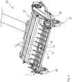
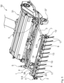
- Figure 1 shows a side view of a mowing device 30 for mowing grass and/or for collecting leaves with a protective device 1 in a transport position, wherein Figure 2 a side view of the mowing device 30 Figure 1 with the protective device 1 in an insect protection position.
- Figure 3 another side view of the mowing device 30 Figure 1 .
- Figure 4 shows a spatial front view of the mowing device 30 from Figure 1
- Figure 5 a spatial front view of the mowing device 30 Figure 2
- Figure 6 shows a spatial rear view of the mowing device 30 from Figure 5 or from Figure 2 .
- Figures 1 to 6 a mowing device 30 for mowing grass and/or collecting leaves.
- the mowing device 30 has a protective device 1 and a mower 31, which can be designed as a horizontal mower or as a rotary mower.
- the protective device 1 is arranged on the mower 31.
- the protective device 1 is a protective device 1 for scaring away insects and for use on a mower 31 of a mowing device 30.
- the protective device 1 has to comply with Figures 1 to 6 a scaring unit 2, with which insects, such as pollen donors or bees, can be attracted and/or scared away.
- the protective device 1 has two holding arms 3, 4, each with a first and a second end 5, 6, wherein the first end 5 is attached to the mower 31 of the mowing device 30.
- the second end 6, however, is connected to the scarer unit 2 in such a way that the scarer unit 2 and the holding arms 3, 4 can be rotated and moved relative to one another.
- This offers the advantage that the distance between the mower 31 and the scarer unit 2, which is determined by the holding arms, can be changed.
- the distance can be changed in such a way that the second end 6 of the holding arms 3, 4 and the scarer unit 2 can not only rotate relative to one another, but can also be moved relative to one another.
- the distance between the mower 31 and the scarer unit 2 can be changed not only by rotating the scarer unit 2 relative to the mower 31, but can also be changed by moving the scarer unit 2 in the direction of the mower 31.
- the protective device 1 is therefore ideally suited for mowing in tight spaces with obstacles, such as trees or signposts, since the protective device 1 enables mowing close to the obstacle.
- the scaring unit 2 comprises a cross member 7, which has a slotted guide 8 for each of the holding arms 3, 4, in which the second end 6 of a holding arm 3, 4 is arranged.
- the second end 6 is guided in the guide rail 8 by means of a bolt 9 (cf. Figures 5 , 6 ).
- Figures 1 to 6 in particular Figures 1 to 3 that the cross member 7 has a U-profile, wherein the equally oriented legs of the U-profile have the slotted guide 8.
- the scare unit 2 comprises a carrier 10 for scare elements 17, wherein the carrier 10 is designed as a tube.
- the carrier 10 is designed to be relatively rotatable and is aligned in the same direction as the cross member 7 of the scare unit 2.
- the scarer unit 2 comprises two bearings 11, 12 in which the carrier 10 is rotatably mounted.
- the two bearings 11, 12 are arranged on the cross member 7 of the scarer unit 2 or on a connecting leg of the U-profile of the cross member 7, which connects two equally oriented legs.
- the scare unit 2 has a first locking mechanism 13, with which several different positions of the carrier 10 of the scare unit 2 relative to the cross member 7 of the scare unit 2 can be assumed or adjusted.
- the first locking mechanism 13 has a locking pin 14 and several locking holes 15, 16 into which the locking pin 14 can be locked (cf. Figure 4 ) to set different positions.
- the carrier 10 of the scare unit 2 has the locking holes 15, 16.
- the locking holes 15, 16 are arranged at different positions on the circumference of the carrier 10 of the scare unit 2, so that a specific locking hole 15, 16 can be selected by rotating the carrier 10 (cf. Figure 4 ).
- a transport position can be set in which the scaring elements 17 of the scaring unit 2 are oriented opposite to the ground E (cf. Figures 1 and 4 ).
- a first working position can be set by means of the first locking mechanism 13, in which the scaring elements 17 of the scaring unit 2 are oriented at a first angle ⁇ to the ground E (cf. Figure 2 ).
- a second working position can be set by means of the first locking mechanism 13, in which the scaring elements 17 of the scaring unit 2 are oriented at a second angle ⁇ to the ground E (cf. Figure 3 ).
- the second angle ⁇ is smaller than the first angle ⁇ , whereby the first angle ⁇ forms 90 degrees with the ground E and the second angle ⁇ forms 40 degrees with the ground E.
- the scaring unit 2 has several scaring elements 17 which are attached to the support 10 of the scaring unit 2.
- the scaring elements 17 are each designed as a spring element that springs back to its original position after the application of force.
- the scaring elements 17 are designed in the form of a tine or a reel tine and are made of plastic. Alternatively, the scaring elements 17 can be designed as a chain.
- each holding arm 3, 4 has a stop 18 with which a holding arm 3, 4 can be struck against a support frame 36 of the mowing mechanism 31 of the mowing device 30 in order to limit the movement of the holding arm 3, 4.
- the stop 18 is arranged at the first end 5 of a holding arm 3, 4 and is designed as a cantilever arm which extends away from the holding arm 3, 4.
- a rubber buffer is arranged on each of the stops 18 for gentle impact against a support frame 36 of the mowing deck 31 of the mowing device 30.
- the scare unit 2 has a second locking mechanism 19 with which the scare unit 2 can be locked to the holding arms 3, 4.
- the second locking mechanism 19 has a first passage 21 and a locking pin 20 which can be inserted into it, wherein the first passage 21 is arranged in the cross member 7 of the scare unit 2 (cf. Figure 6 ).
- the second locking mechanism 19 has a locking unit 22 on each of the holding arms 3, 4, wherein the locking unit 22 comprises a metal sheet 23 with a second passage 24 for the locking pin 20.
- the locking unit 22 is arranged at the first end 5 of each holding arm 3, 4.
- the holding arms 3, 4 can be fixed in such a way that a relative displacement or twisting between the scarer unit 2 and the holding arms 3, 4 can be prevented (cf. Figure 4 ).
- the mower 31 has a spring and damper element 32, 33 per holding arm 3, 4 of the protective device 1 in order to pre-tension the holding arms 3, 4 into an insect protection position (cf. Figures 6 and 2, 3 ).
- Each spring and damper element 32, 33 is designed as a gas spring. Furthermore, each spring and damper element 32, 33 comprises a first and a second end 34, 35, wherein the first end 34 is attached to the holding arm 3, 4 and the second end 35 is attached to a support frame 36 of the mower 31.
- the mower 31 comprises a support frame 36 to which support wheels 37, 38 are rotatably attached.
- the mower 31 has two support wheels 37, 38, to whose rotation axes a support arm 3, 4 of the protective device 1 is rotatably attached.
- the support frame 36 comprises two holding elements 39, 40, each designed as a U-shaped holding bracket, to each of which a second end 35 of the spring and damper element 32, 33 of the mower 31 is fastened.
- the support frame 36 spaces the protective device 1 from the ground E in such a way that the scaring elements 17 of the scaring unit 2 of the protective device 1 can be moved over the ground E without contact.
- two holding arms 3, 4, two spring and damper elements 32, 33 and the two holding elements 39, 40 are positioned and designed relative to each other in such a way that the protective device 1 can be moved into a transport position (cf. Figures 1 and 4 ) and in an insect protection position (cf. Figures 2, 3 and 5 , 6 ) can be brought.
- the protective device 1 In the transport position, the protective device 1 has a first distance from the mower 31, wherein in the transport position the second locking mechanism 19 of the protective device 1 is locked.
- the locking pin 20 of the second locking mechanism 19 connects the first end 5 of a holding arm 3, 4 to the scarer unit 2, whereby the second end 6 of a holding arm 3, 4 has a first distance from the mower 31.
- the protective device 1 In the insect protection position, however, the protective device 1 has a second distance from the mower 31, whereby in the insect protection position the second locking mechanism 19 of the protective device 1 is unlocked (cf. Figures 2, 3 and 5 , 6 ). Each locking pin 20 of the second locking mechanism 19 releases the connection between the first end 5 of a holding arm 3, 4 and the scarer unit 2, whereby the second end 6 of a holding arm 3, 4 has a second distance from the mowing mechanism 31.
- the first distance between scaring unit 2 and mower 31 can be seen from e.g. Figure 1 is smaller than the second distance between scarer unit 2 and mower 31 from Figure 2 This saves volume, making the mowing device 30 easier to transport.
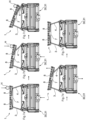
- the mowing device 30 for mowing grass and/or for picking up leaves is designed and constructed in such a way that when an obstacle H comes into contact with the protective device 1, the mowing mechanism 31 can be switched off and/or the driving speed of the mowing device 30 can be reduced. Furthermore, the direction of travel of the mowing device 30 can be automatically reversed in order to automatically reset the mowing device 30 away from an obstacle H (cf. Figures 7d )).
- the mower 31 and the protective device 1 each have a sensor device (not shown) that can detect a movement of the protective device 1 and a movement of the mower 31.
- the sensor devices have an accelerometer.
- the mowing device 30 comprises a control unit (not shown) which is connected to the sensor devices in order to receive the data from the sensor devices.
- the control unit can, for example, reduce the driving speed of the mowing device 30 and/or reverse the direction of travel and/or switch off the mowing mechanism when certain values are received from the sensor devices.
- control unit (not shown) can be designed to determine the relative acceleration of the protective device 1 to the mower 31 by comparing the data from the sensor device of the protective device 1 and a sensor device of the mower 31 in order to determine whether there is an obstacle. This also makes it possible to detect an obstacle that is driving against the protective device 1 or its scaring unit 2 even more precisely.
- an aggregate or a protective device 1 is mounted at the front of a mower 31 of a mowing device 30 (e.g. on pivot axes of the support wheels 37, 38).
- the grass When mowing, the grass is shaken by the tine carrier or by the carrier 10 of a scaring unit 2 of the protective device 1 before the mowing process in order to scare away and flush out flying insects in the grass so that they can be protected from harm.
- a tine carrier 10 or the carrier 10 of the scaring unit 2 is formed from a tube and has tines or scaring elements 17 (combine harvester - reel tine technology) made of deformable plastic.
- the tines or scaring elements 17 are not in contact with the ground E.
- the tine carrier or support 10 is rotatably mounted in two bearings 11, 12.
- the support 10 has several positions that can be adjusted by a locking bolt 14.
- a transport position (tines up and to the rear - see Figures 1 and 4 ), a first working position in which short and medium grass (tines or scaring elements 17 are arranged below: approximately 10 cm above ground level E - see Figure 2) can be mown and a second working position in which long grass (tines or scaring elements 17 are arranged below and to the rear: approximately 25 cm above ground level E - see Figure 3 ) can be mown.
- the tine carrier or carrier 10 is attached to a cross member 7 including the bearings 11, 12.
- the cross member 7 contains two curved tracks or guide rails 8 in which two support arms 3, 4 or holding arms 3, 4 can be moved by bolts 9.
- the support arms 3, 4 or holding arms 3, 4 are mounted on mower support wheels or support wheels 37, 38 and rotate about their axes of rotation.
- the support arms 3, 4 are dampened laterally by spring and damper elements 32, 33 (the end point of which is fixed to the mower frame or to the support frame 36 of the mower 31 of the mowing device 30).
- the kinematics allow two positions, namely a folded position or a transport position and an unfolded position or an insect protection position.
- the folded-in position (including the tine carriers or deterrent elements 17 turned upwards and backwards) serves as a transport position or for a mowing process without insect protection.
- the unit or the protective device 1 can therefore also be used for driving on a road.
- the folded-in position is locked by means of linch pins 20 or locking pins 20.
- the unfolded position serves as an insect deterrent or as an insect protection position.
- the position of the tines or blades is adjusted depending on the grass conditions.
- the deterrent elements 17 are selected, whether aggressive (large angle ⁇ - cf. Figure 2 ) or less aggressive (small angle ⁇ - cf. Figure 3 ) is being worked on.
- Two handles enable ergonomic operation of the unit or the protective device 1 (folded in or unfolded).
- the back and forth or left or right movement of the tine carrier or the carrier 10 is limited by two rubber buffers or stops 18 with rubber buffers.
- the tines can deform and/or the unit 1 or the entire protective device 1 can give way in the event of a collision with an obstacle H in order to protect the mowing device 30 from damage.
- the protective device 1 After a collision with the obstacle H and a subsequent reversing movement, the protective device 1 returns to its original position (thanks to the spring and damper elements 32, 33) (cf. Figures 7d ) and e)).
- FIG. 8a and 8b Another or second embodiment of the mowing device 30 according to the invention is shown in the Figures 8a and 8b shown.
- the holding arms 3.1, 4.1 are variable in length, in particular telescopic and/or designed in the manner of a spring and/or damper element.
- the holding arms 3.1, 4.1 are designed to automatically change their length in the event of a collision between the scaring unit 2 and the obstacle H.
- the holding arms 3.1, 4.1 are designed to automatically return to and/or assume their original length and/or starting position after the collision.
- a holding arm 3.1, 4.1 designed in this way can also be equipped with the features or combinations of features of the mowing device 30 according to the embodiments in Figures 1 to 7e can be combined.
- FIG. 9a and 9b A further different or third embodiment of the mowing device 30 according to the invention is shown in the Figures 9a and 9b This shows a combination of the previous embodiment, in particular in which the variable length Holding arms 3.1, 4.1 are coupled to the link guides 8.
- the guide or the degree of freedom of the holding arms 3.1, 4.1, in particular the second ends 6, is locked transversely to the travel and/or working direction and in operation or working position.
- the guide or the degree of freedom transversely to the travel and/or working direction can be released (manually) to adjust the scare unit 2, for example to adjust the scare unit 2 from the working position to the transport position or inoperative position or vice versa.
- the relative displacement of the scare unit 2, in the event of a collision with an obstacle H results from the change in length of the holding arms 3.1, 4.1.
- the guide rails 8 and thus the guidance or the degree of freedom of the holding arms 3.1, 4.1, in particular the second ends 6, are released during operation at least in sections along the guide rails 8.
- the relative displacement of the scaring unit 2, in particular the cross member 7, in the event of a collision with an obstacle H results from the change in length of the holding arms 3.1, 4.1 and the at least partial guidance of the second ends 6 along the guide rails 8.
Landscapes
- Life Sciences & Earth Sciences (AREA)
- Environmental Sciences (AREA)
- Insects & Arthropods (AREA)
- Pest Control & Pesticides (AREA)
- Birds (AREA)
- Engineering & Computer Science (AREA)
- Wood Science & Technology (AREA)
- Zoology (AREA)
- Harvester Elements (AREA)
Applications Claiming Priority (1)
| Application Number | Priority Date | Filing Date | Title |
|---|---|---|---|
| DE102023101091.3A DE102023101091A1 (de) | 2023-01-18 | 2023-01-18 | Schutzeinrichtung zum Aufscheuchen von Insekten und zum Einsatz an einem Mähwerk an einer Mähvorrichtung sowie Mähvorrichtung |
Publications (3)
| Publication Number | Publication Date |
|---|---|
| EP4403015A1 true EP4403015A1 (fr) | 2024-07-24 |
| EP4403015C0 EP4403015C0 (fr) | 2025-07-16 |
| EP4403015B1 EP4403015B1 (fr) | 2025-07-16 |
Family
ID=89833797
Family Applications (1)
| Application Number | Title | Priority Date | Filing Date |
|---|---|---|---|
| EP24401001.3A Active EP4403015B1 (fr) | 2023-01-18 | 2024-01-09 | Dispositif de protection pour effrayer des insectes et destiné à être utilisé sur une unité de tonte d'une faucheuse et faucheuse |
Country Status (3)
| Country | Link |
|---|---|
| EP (1) | EP4403015B1 (fr) |
| DE (1) | DE102023101091A1 (fr) |
| PL (1) | PL4403015T3 (fr) |
Families Citing this family (1)
| Publication number | Priority date | Publication date | Assignee | Title |
|---|---|---|---|---|
| US12543650B2 (en) * | 2017-11-08 | 2026-02-10 | James Steven Hess | Lawn mower diverter/ bee guard or accessory warning device for diverting and saving honeybees and other endangered insects |
Citations (5)
| Publication number | Priority date | Publication date | Assignee | Title |
|---|---|---|---|---|
| CH657247A5 (en) * | 1982-06-10 | 1986-08-29 | Walter Junker | Mowing machine with an animal-protection device |
| DE202015006431U1 (de) * | 2015-09-11 | 2015-10-26 | Andreas Geibert | Insektenschutz zum Anbringen an Rasemähern |
| US20190133090A1 (en) * | 2017-11-08 | 2019-05-09 | James Steven Hess | Lawn mower plow or accessory warning device for diverting and saving honey bees and other endangered insects |
| DE102020118051A1 (de) | 2019-12-23 | 2021-06-24 | Mulag Fahrzeugwerk Heinz Wössner GmbH u. Co KG | Kreisel-Mähkopf sowie Verfahren für seinen Betrieb |
| DE102020207095A1 (de) * | 2020-06-05 | 2021-12-09 | Hochschule für Technik und Wirtschaft Dresden (FH) Körperschaft des öffentlichen Rechts | System und Verfahren zur Schonung von Insekten bei der landwirtschaftlichen Pflanzenproduktion |
Family Cites Families (3)
| Publication number | Priority date | Publication date | Assignee | Title |
|---|---|---|---|---|
| DE8317044U1 (de) * | 1982-06-10 | 1983-11-17 | Junker, Walter, 9553 Bettwiesen | Mähmaschine mit Tierschutzgerät |
| NL2017019B1 (en) * | 2016-06-21 | 2018-01-04 | Forage Co Bv | Mower |
| FR3120496B1 (fr) * | 2021-03-10 | 2024-04-19 | Agri Structures | « Dispositif d’effarouchement » |
-
2023
- 2023-01-18 DE DE102023101091.3A patent/DE102023101091A1/de active Pending
-
2024
- 2024-01-09 EP EP24401001.3A patent/EP4403015B1/fr active Active
- 2024-01-09 PL PL24401001.3T patent/PL4403015T3/pl unknown
Patent Citations (5)
| Publication number | Priority date | Publication date | Assignee | Title |
|---|---|---|---|---|
| CH657247A5 (en) * | 1982-06-10 | 1986-08-29 | Walter Junker | Mowing machine with an animal-protection device |
| DE202015006431U1 (de) * | 2015-09-11 | 2015-10-26 | Andreas Geibert | Insektenschutz zum Anbringen an Rasemähern |
| US20190133090A1 (en) * | 2017-11-08 | 2019-05-09 | James Steven Hess | Lawn mower plow or accessory warning device for diverting and saving honey bees and other endangered insects |
| DE102020118051A1 (de) | 2019-12-23 | 2021-06-24 | Mulag Fahrzeugwerk Heinz Wössner GmbH u. Co KG | Kreisel-Mähkopf sowie Verfahren für seinen Betrieb |
| DE102020207095A1 (de) * | 2020-06-05 | 2021-12-09 | Hochschule für Technik und Wirtschaft Dresden (FH) Körperschaft des öffentlichen Rechts | System und Verfahren zur Schonung von Insekten bei der landwirtschaftlichen Pflanzenproduktion |
Also Published As
| Publication number | Publication date |
|---|---|
| EP4403015C0 (fr) | 2025-07-16 |
| EP4403015B1 (fr) | 2025-07-16 |
| PL4403015T3 (pl) | 2025-09-08 |
| DE102023101091A1 (de) | 2024-07-18 |
Similar Documents
| Publication | Publication Date | Title |
|---|---|---|
| DD209711A5 (de) | Bodenbearbeitungsgeraet | |
| DE10128547B4 (de) | Arbeitsgerät zum Anbau an ein Fahrzeug | |
| EP4403015B1 (fr) | Dispositif de protection pour effrayer des insectes et destiné à être utilisé sur une unité de tonte d'une faucheuse et faucheuse | |
| EP1095555A1 (fr) | Machine de fenaison | |
| EP3977851B1 (fr) | Herse étrille destinée au traitement du sol pourvue de dents à réglage synchrone | |
| DE10149364B4 (de) | Mähmaschine | |
| DE102020202976A1 (de) | Erntevorsatz mit Mulchgeräten zur Bearbeitung von auf einem Feld stehenden Pflanzenstümpfen mit verbessertem Schutz gegen abgeschleuderte Steine | |
| EP0807376A2 (fr) | Protection de collision pour une faucheuse connectable à un véhicule | |
| EP2591653A1 (fr) | Machine de fenaison | |
| DE68906399T2 (de) | Vorrichtung zum mähen von gras oder ähnlichen pflanzen. | |
| DE2058255A1 (de) | Mit Abweisern am Schneidwerktisch versehener Maehdrescher | |
| EP1588601B1 (fr) | Machine de récolte avec un dispositif de décharge | |
| EP0834053B1 (fr) | Dispositif de camouflage d'equipements militaires | |
| DE102011113121A1 (de) | Kombinierbarer Sternradschwader | |
| EP3479669B1 (fr) | Machine agricole | |
| EP1093709B1 (fr) | Appareil récolteur avec moyens de guidage de décharge | |
| DE19604758A1 (de) | Vorrichtung zum Ausdünnen von Obstbäumen oder anderen mit Ästen und Zweigen versehenen Fruchtgehölzen | |
| DE102010020431B4 (de) | Mähmaschine | |
| EP3616495A1 (fr) | Mécanisme de fixation pour un dispositif de broyage / de coupe pour matière végétale sur un véhicule, en particulier un tracteur ou analogue | |
| DE102005051551B4 (de) | Mähmaschine | |
| DE3617815A1 (de) | Anbaueinheit fuer einen frontmulcher an einem ackerschlepper | |
| DE102023123622A1 (de) | Erntevorsatz für eine selbstfahrende Erntemaschine | |
| DE3724952C1 (en) | Agricultural reaping machine | |
| EP3332628A1 (fr) | Engin agricole | |
| DE202020100868U1 (de) | Mähwerksanordnung |
Legal Events
| Date | Code | Title | Description |
|---|---|---|---|
| PUAI | Public reference made under article 153(3) epc to a published international application that has entered the european phase |
Free format text: ORIGINAL CODE: 0009012 |
|
| STAA | Information on the status of an ep patent application or granted ep patent |
Free format text: STATUS: THE APPLICATION HAS BEEN PUBLISHED |
|
| AK | Designated contracting states |
Kind code of ref document: A1 Designated state(s): AL AT BE BG CH CY CZ DE DK EE ES FI FR GB GR HR HU IE IS IT LI LT LU LV MC ME MK MT NL NO PL PT RO RS SE SI SK SM TR |
|
| STAA | Information on the status of an ep patent application or granted ep patent |
Free format text: STATUS: REQUEST FOR EXAMINATION WAS MADE |
|
| 17P | Request for examination filed |
Effective date: 20241121 |
|
| RBV | Designated contracting states (corrected) |
Designated state(s): AL AT BE BG CH CY CZ DE DK EE ES FI FR GB GR HR HU IE IS IT LI LT LU LV MC ME MK MT NL NO PL PT RO RS SE SI SK SM TR |
|
| GRAP | Despatch of communication of intention to grant a patent |
Free format text: ORIGINAL CODE: EPIDOSNIGR1 |
|
| STAA | Information on the status of an ep patent application or granted ep patent |
Free format text: STATUS: GRANT OF PATENT IS INTENDED |
|
| RIC1 | Information provided on ipc code assigned before grant |
Ipc: A01M 29/34 20110101ALI20250220BHEP Ipc: A01D 75/20 20060101ALI20250220BHEP Ipc: A01D 34/82 20060101AFI20250220BHEP |
|
| INTG | Intention to grant announced |
Effective date: 20250312 |
|
| GRAS | Grant fee paid |
Free format text: ORIGINAL CODE: EPIDOSNIGR3 |
|
| GRAA | (expected) grant |
Free format text: ORIGINAL CODE: 0009210 |
|
| STAA | Information on the status of an ep patent application or granted ep patent |
Free format text: STATUS: THE PATENT HAS BEEN GRANTED |
|
| AK | Designated contracting states |
Kind code of ref document: B1 Designated state(s): AL AT BE BG CH CY CZ DE DK EE ES FI FR GB GR HR HU IE IS IT LI LT LU LV MC ME MK MT NL NO PL PT RO RS SE SI SK SM TR |
|
| REG | Reference to a national code |
Ref country code: GB Ref legal event code: FG4D Free format text: NOT ENGLISH |
|
| REG | Reference to a national code |
Ref country code: CH Ref legal event code: EP Ref country code: DE Ref legal event code: R096 Ref document number: 502024000108 Country of ref document: DE |
|
| REG | Reference to a national code |
Ref country code: IE Ref legal event code: FG4D Free format text: LANGUAGE OF EP DOCUMENT: GERMAN |
|
| U01 | Request for unitary effect filed |
Effective date: 20250805 |
|
| U07 | Unitary effect registered |
Designated state(s): AT BE BG DE DK EE FI FR IT LT LU LV MT NL PT RO SE SI Effective date: 20250818 |
|
| PG25 | Lapsed in a contracting state [announced via postgrant information from national office to epo] |
Ref country code: IS Free format text: LAPSE BECAUSE OF FAILURE TO SUBMIT A TRANSLATION OF THE DESCRIPTION OR TO PAY THE FEE WITHIN THE PRESCRIBED TIME-LIMIT Effective date: 20251116 |
|
| PG25 | Lapsed in a contracting state [announced via postgrant information from national office to epo] |
Ref country code: NO Free format text: LAPSE BECAUSE OF FAILURE TO SUBMIT A TRANSLATION OF THE DESCRIPTION OR TO PAY THE FEE WITHIN THE PRESCRIBED TIME-LIMIT Effective date: 20251016 |
|
| U20 | Renewal fee for the european patent with unitary effect paid |
Year of fee payment: 3 Effective date: 20251205 |
|
| PG25 | Lapsed in a contracting state [announced via postgrant information from national office to epo] |
Ref country code: HR Free format text: LAPSE BECAUSE OF FAILURE TO SUBMIT A TRANSLATION OF THE DESCRIPTION OR TO PAY THE FEE WITHIN THE PRESCRIBED TIME-LIMIT Effective date: 20250716 |
|
| PG25 | Lapsed in a contracting state [announced via postgrant information from national office to epo] |
Ref country code: GR Free format text: LAPSE BECAUSE OF FAILURE TO SUBMIT A TRANSLATION OF THE DESCRIPTION OR TO PAY THE FEE WITHIN THE PRESCRIBED TIME-LIMIT Effective date: 20251017 |
|
| PG25 | Lapsed in a contracting state [announced via postgrant information from national office to epo] |
Ref country code: RS Free format text: LAPSE BECAUSE OF FAILURE TO SUBMIT A TRANSLATION OF THE DESCRIPTION OR TO PAY THE FEE WITHIN THE PRESCRIBED TIME-LIMIT Effective date: 20251016 |
|
| PG25 | Lapsed in a contracting state [announced via postgrant information from national office to epo] |
Ref country code: ES Free format text: LAPSE BECAUSE OF FAILURE TO SUBMIT A TRANSLATION OF THE DESCRIPTION OR TO PAY THE FEE WITHIN THE PRESCRIBED TIME-LIMIT Effective date: 20250716 |
|
| PG25 | Lapsed in a contracting state [announced via postgrant information from national office to epo] |
Ref country code: SM Free format text: LAPSE BECAUSE OF FAILURE TO SUBMIT A TRANSLATION OF THE DESCRIPTION OR TO PAY THE FEE WITHIN THE PRESCRIBED TIME-LIMIT Effective date: 20250716 |
|
| PG25 | Lapsed in a contracting state [announced via postgrant information from national office to epo] |
Ref country code: CZ Free format text: LAPSE BECAUSE OF FAILURE TO SUBMIT A TRANSLATION OF THE DESCRIPTION OR TO PAY THE FEE WITHIN THE PRESCRIBED TIME-LIMIT Effective date: 20250716 |
|
| PGFP | Annual fee paid to national office [announced via postgrant information from national office to epo] |
Ref country code: PL Payment date: 20251212 Year of fee payment: 3 |
|
| PG25 | Lapsed in a contracting state [announced via postgrant information from national office to epo] |
Ref country code: SK Free format text: LAPSE BECAUSE OF FAILURE TO SUBMIT A TRANSLATION OF THE DESCRIPTION OR TO PAY THE FEE WITHIN THE PRESCRIBED TIME-LIMIT Effective date: 20250716 |