EP4403206A2 - Augenimpedanzbasiertes system zur überwachung der gehirngesundheit - Google Patents
Augenimpedanzbasiertes system zur überwachung der gehirngesundheit Download PDFInfo
- Publication number
- EP4403206A2 EP4403206A2 EP24180772.6A EP24180772A EP4403206A2 EP 4403206 A2 EP4403206 A2 EP 4403206A2 EP 24180772 A EP24180772 A EP 24180772A EP 4403206 A2 EP4403206 A2 EP 4403206A2
- Authority
- EP
- European Patent Office
- Prior art keywords
- brain
- ocular
- subject
- bioimpedance
- stimulation
- Prior art date
- Legal status (The legal status is an assumption and is not a legal conclusion. Google has not performed a legal analysis and makes no representation as to the accuracy of the status listed.)
- Granted
Links
Images



Classifications
-
- A—HUMAN NECESSITIES
- A61—MEDICAL OR VETERINARY SCIENCE; HYGIENE
- A61N—ELECTROTHERAPY; MAGNETOTHERAPY; RADIATION THERAPY; ULTRASOUND THERAPY
- A61N1/00—Electrotherapy; Circuits therefor
- A61N1/02—Details
- A61N1/08—Arrangements or circuits for monitoring, protecting, controlling or indicating
-
- A—HUMAN NECESSITIES
- A61—MEDICAL OR VETERINARY SCIENCE; HYGIENE
- A61B—DIAGNOSIS; SURGERY; IDENTIFICATION
- A61B5/00—Measuring for diagnostic purposes; Identification of persons
- A61B5/02—Detecting, measuring or recording for evaluating the cardiovascular system, e.g. pulse, heart rate, blood pressure or blood flow
- A61B5/026—Measuring blood flow
-
- A—HUMAN NECESSITIES
- A61—MEDICAL OR VETERINARY SCIENCE; HYGIENE
- A61B—DIAGNOSIS; SURGERY; IDENTIFICATION
- A61B5/00—Measuring for diagnostic purposes; Identification of persons
- A61B5/03—Measuring fluid pressure within the body other than blood pressure, e.g. cerebral pressure ; Measuring pressure in body tissues or organs
- A61B5/031—Intracranial pressure
-
- A—HUMAN NECESSITIES
- A61—MEDICAL OR VETERINARY SCIENCE; HYGIENE
- A61B—DIAGNOSIS; SURGERY; IDENTIFICATION
- A61B5/00—Measuring for diagnostic purposes; Identification of persons
- A61B5/05—Detecting, measuring or recording for diagnosis by means of electric currents or magnetic fields; Measuring using microwaves or radio waves
- A61B5/053—Measuring electrical impedance or conductance of a portion of the body
-
- A—HUMAN NECESSITIES
- A61—MEDICAL OR VETERINARY SCIENCE; HYGIENE
- A61B—DIAGNOSIS; SURGERY; IDENTIFICATION
- A61B5/00—Measuring for diagnostic purposes; Identification of persons
- A61B5/08—Measuring devices for evaluating the respiratory organs
- A61B5/0816—Measuring devices for examining respiratory frequency
-
- A—HUMAN NECESSITIES
- A61—MEDICAL OR VETERINARY SCIENCE; HYGIENE
- A61B—DIAGNOSIS; SURGERY; IDENTIFICATION
- A61B5/00—Measuring for diagnostic purposes; Identification of persons
- A61B5/40—Detecting, measuring or recording for evaluating the nervous system
- A61B5/4058—Detecting, measuring or recording for evaluating the nervous system for evaluating the central nervous system
- A61B5/4064—Evaluating the brain
-
- A—HUMAN NECESSITIES
- A61—MEDICAL OR VETERINARY SCIENCE; HYGIENE
- A61B—DIAGNOSIS; SURGERY; IDENTIFICATION
- A61B5/00—Measuring for diagnostic purposes; Identification of persons
- A61B5/48—Other medical applications
- A61B5/4836—Diagnosis combined with treatment in closed-loop systems or methods
-
- A—HUMAN NECESSITIES
- A61—MEDICAL OR VETERINARY SCIENCE; HYGIENE
- A61B—DIAGNOSIS; SURGERY; IDENTIFICATION
- A61B5/00—Measuring for diagnostic purposes; Identification of persons
- A61B5/68—Arrangements of detecting, measuring or recording means, e.g. sensors, in relation to patient
- A61B5/6801—Arrangements of detecting, measuring or recording means, e.g. sensors, in relation to patient specially adapted to be attached to or worn on the body surface
- A61B5/6802—Sensor mounted on worn items
- A61B5/6803—Head-worn items, e.g. helmets, masks, headphones or goggles
-
- A—HUMAN NECESSITIES
- A61—MEDICAL OR VETERINARY SCIENCE; HYGIENE
- A61N—ELECTROTHERAPY; MAGNETOTHERAPY; RADIATION THERAPY; ULTRASOUND THERAPY
- A61N1/00—Electrotherapy; Circuits therefor
- A61N1/02—Details
- A61N1/04—Electrodes
- A61N1/0404—Electrodes for external use
- A61N1/0408—Use-related aspects
- A61N1/0456—Specially adapted for transcutaneous electrical nerve stimulation [TENS]
-
- A—HUMAN NECESSITIES
- A61—MEDICAL OR VETERINARY SCIENCE; HYGIENE
- A61N—ELECTROTHERAPY; MAGNETOTHERAPY; RADIATION THERAPY; ULTRASOUND THERAPY
- A61N1/00—Electrotherapy; Circuits therefor
- A61N1/02—Details
- A61N1/04—Electrodes
- A61N1/0404—Electrodes for external use
- A61N1/0472—Structure-related aspects
- A61N1/0476—Array electrodes (including any electrode arrangement with more than one electrode for at least one of the polarities)
-
- A—HUMAN NECESSITIES
- A61—MEDICAL OR VETERINARY SCIENCE; HYGIENE
- A61N—ELECTROTHERAPY; MAGNETOTHERAPY; RADIATION THERAPY; ULTRASOUND THERAPY
- A61N1/00—Electrotherapy; Circuits therefor
- A61N1/18—Applying electric currents by contact electrodes
- A61N1/32—Applying electric currents by contact electrodes alternating or intermittent currents
- A61N1/36—Applying electric currents by contact electrodes alternating or intermittent currents for stimulation
- A61N1/36014—External stimulators, e.g. with patch electrodes
- A61N1/36025—External stimulators, e.g. with patch electrodes for treating a mental or cerebral condition
Definitions
- the present disclosure relates generally to techniques for monitoring and assessing brain health and, more particularly, to techniques for using an ocular impedance measurement to monitor and assess brain health.
- Traumatic brain injury plays a major role in approximately 30% of injury related deaths in the United States and is often referred to as the "silent epidemic" due to associated complications that go undiagnosed and unnoticed, but that may have a lasting effect on health.
- Management strategies in the treatment of severe-TBI are usually aimed at preventing secondary brain injury, which mainly manifests itself as inflammation and brain ischemia.
- Monitoring of intracranial pressure (ICP) and optimization of cerebral perfusion pressure (CPP) to a target level have been proposed in the past as primary methods to prevent secondary injury and are the backbones of current practice.
- ICP intracranial pressure
- CPP cerebral perfusion pressure
- CAR cerebrovascular autoregulation
- PRx pressure reactivity index
- CBV cerebral blood volume
- a portable, non-invasive sensor for measuring CBV changes in casualties with traumatic head injury and other cerebrovascular emergencies, suitable for use in varied environments (e.g., in civilian and military prehospital settings, emergency department trauma centers, intensive care units, etc.). This will allow early precision monitoring and treatment to prevent secondary brain damage.
- the present techniques include methods and systems that monitor and assess brain bioimpedance through an ocular window as a method of assessing dynamic changes in cerebral blood volume (CBV).
- CBV cerebral blood volume
- the techniques may be achieved in a non-invasive and continuous manner.
- the techniques monitor brain impedance to track changes in CBF, ICP and CPP that are associated with changes in cerebral blood volume. In this way, the techniques may be additionally used to evaluate CAR impairment.
- the present techniques provide a non-invasive way to measure numerous different brain health indicators using impedance measurements collected through the eye(s) of a subject.
- An ocular bioimpedance device is used to particularly localize measurement electrodes which may include combinations of cathodes and anodes.
- an apparatus for evaluating brain health of a subject comprises: one or more electrodes; one or more processors; a computer-readable memory storing non-transient instructions that when executed by the one or more processors cause the apparatus to: provide, using the one or more electrodes, electrical current to an ocular region of the subject; sense, using the one or more electrodes, an electrical signal obtained from the ocular region of the subject, and determine a bioimpedance value of the subject from the electrical signal, wherein the bioimpedance value represents a bioimpedance for a conduction path that includes at least a portion of the ocular and brain regions of the subject; and determine a brain health indicator from the bioimpedance information.
- a method of evaluating brain health of a subject comprising: in response to the provision of an electrical signal to an ocular region of a subject and detection of the electrical signal over a conduction path that includes at the ocular region and at least a portion of a brain region, determining an ocular-brain region bioimpedance value of the subject; determining, from the ocular-brain region bioimpedance value, changes in intracranial pressure over a sample time period, those changes corresponding to changes in cerebral blood volume (CBV); determining the effects of arterial pressure of the subject on CBV over the sample time period; determining the effects of mean intracranial pressure over the sample time period and mean arterial pressure over the sample time period on CBV; and determining a pressure reactivity index value from a correlation of the mean intracranial pressure and the mean arterial pressure, the pressure reactivity index on CBV indicating the brain health of the subject.
- CBV cerebral blood volume
- a method of evaluating brain health of a subject comprising: receiving mean intracranial pressure data of the subject over a sample time period; receiving mean arterial pressure data for the subject over the sample time period; receiving a pressure reactivity index value determined from a correlation of the mean intracranial pressure and the mean arterial pressure, the pressure reactivity index indicating a brain health of the subject; in response to the provision of an electrical signal to an ocular region of the subject and detection of the electrical signal over a conduction path that includes at the ocular region and at least a portion of a brain region, determining an ocular-brain region bioimpedance of the subject over the sample time period; and combining the bioimpedance with the pressure reactivity index and producing a brain health indicator, the indicator having a positive value indicating a healthy brain state of the subject and a negative value indicating an unhealthy brain state of the subject.
- a method of treating a brain condition of a subject comprising: applying, to an ocular region of the subject, a brain-condition affecting treatment to the subject, the brain-condition affecting treatment being a transcranial direct current stimulation (tDCS), a transcranial alternating current stimulation (tACS), a biophotonic stimulation, and/or an acoustic stimulation.
- tDCS transcranial direct current stimulation
- tACS transcranial alternating current stimulation
- biophotonic stimulation a biophotonic stimulation
- acoustic stimulation an acoustic stimulation.
- an apparatus for treating a brain condition of a subject comprising: a housing configured to engage an ocular region of the subject, the housing having one or more electrodes configured to deliver electrical signals to the ocular region of the subject; one or more processors; a computer-readable memory storing non-transient instructions that when executed by the one or more processors cause the apparatus to: supply, using the one or more electrodes, an electrical signal in the form of a transcranial direct current stimulation (tDCS) and/or a transcranial alternating current stimulation (tACS) to the ocular region of the subject to treat the brain condition.
- tDCS transcranial direct current stimulation
- tACS transcranial alternating current stimulation
- Bioimpedance is a measure of tissue resistance to an induced current or voltage.
- bioimpedance When the current is applied to the body, either as a whole or a portion thereof, bioimpedance will represent a cumulative effect of the impedances of each of the components through which the current flows. These components might include muscle tissue, bone, fat, intracellular and extracellular fluid, and blood. Blood, being a good conductor, has a distinct effect on impedance. Hence, physiologic or other induced events which modulate blood volume in an area of interest can be detected with impedance. An example of this is the effect of ventilation and even the cardiac cycle ( FIG. 5 ). Therefore, the electrical impedance across a segment of tissue increases with decreased blood volume and decreases with increased blood volume.
- FIG. 6 illustrates trends and changes over time for MAP, ICP, CBF and impedance during the creation then removal of an epidural hematoma, a type of traumatic brain injury. As the plots of FIG. 6 demonstrate, impedance (dz) increases with decreased blood volume (i.e., decreased CBF) and vice versa.
- the present techniques provide methods and systems to measure brain bioimpedance through the eyes, or other portions of the ocular region, using a bipolar arrangement.
- Example ocular bioimpedance devices are illustrated in FIGS. 7-9 , 11, and 12 . Because of the fluid interface and close proximity of the ocular bioimpedance devices to the brain along with a decrease in intervening tissues (hair, scalp, muscle, bone) and the direct connection of the ocular nerve to the brain, the present devices are able to ensure that the brain will encounter a significant portion of the electrical current sent through the devices. As small current may be applied through the eyes and the resulting the measured conductivity differences reflect the blood volume between the electrodes, which will include a large portion of the brain.
- bioimpedance through ocular measurements using various experimental maneuvers, such as through increasing ICP using inflation of the epidural balloon to demonstrate that changes in scalp or facial soft tissue blood flow are not responsible for the noted changes in impedance measured by the present techniques.
- the present techniques provide unexpected improvement in measuring bioimpedance and correlating that measurement to indicators of brain health, such as CBF, ICP and CPP.
- the techniques herein can be used to provide early evaluation of a patient with TBI or other cerebral insult, as a mechanism to evaluate CAR or the effect of other therapies on changes in cerebral blood volume prior to performing an invasive monitoring procedure on the patient or in conjunction with such invasive monitoring.
- the present techniques may be combined with other monitoring techniques.
- approaches such as calculation of the pressure reactivity index (PRx) (a moving Pearson correlation between mean arterial pressure MAP and ICP) have been shown to provide an independent predictor of brain health.
- PRx pressure reactivity index
- bioimpedance techniques herein may be used in conjunction with PRx, where using an additional simultaneous measure such as cerebral impedance may allow improved use of PRx, which is an otherwise high noise measurement.
- overall tissue impedance changes over time, varies among individuals, and might be affected by the type and placement of electrodes (cathodes and anodes) the present techniques may reduce these effects by normalizing the impedance wave to its basal value negating the need to index to a baseline or normal value.
- a PRx type measure utilizing MAP and cerebral impedance may be used as a precision measure of CAR.
- the techniques herein can be used with PRx, and CAR more broadly in a number of ways.
- the bioimpedance measurement techniques herein are used to determine ICP from which a more accurate PRx value can be determined, and a more accurate assessment of CAR results.
- PRx may be determined independently, for example through known techniques, and the PRx value may be correlated with bioimpedance for a more accurate assessment of CAR.
- PRx is determined independently and then correlated with bioimpedance measured using the techniques described herein.
- the bioimpedance can be combined with the pressure reactivity index to produce a brain health indicator, where, like the PRx value itself, that indicator having a negative value indicates a healthy brain state of the subject (i.e., an intact autoregulation) and the indicator having a positive value indicates an unhealthy brain state of the subject (i.e., an impaired autoregulation).
- the combination is a mathematical combination. For example, where the two values can be correlated over a sample time period using a moving Pearson correlation. Additionally, a moving Pearson correlation could be produced using MAP and dz measured by bioimpedance allowing both PRx and the additional MAP and dz correlation to be compared and tracked together.
- brain bioimpedance measured through the ocular brain interface can be used to track changes in CPP and CBF with high precision and are valuable assessing changes in cerebral blood volume and CAR.
- the mechanical ventilator was initially set at baseline between 15-18 BPM to achieve an end tidal CO2 (PetCO2) at 35-40mmHg. After baseline line readings, the respiratory rate (RR) was then increased fourfold in increments of 10 breaths until PetCO2 reached ⁇ 20mmHg. PetCO2 was maintained at ⁇ 20mmHg for 5-10min. RR was then decreased to baseline levels.
- vascular pressor (norepinephrine) administration Norepinephrine (4 ⁇ g/ml) was mixed with 500mL of 5% dextrose, administered by continuous infusion and titrated to reach an MAP of 160 mmHg or greater. MAP was maintained at 160 mmHg or greater for 5 minutes followed by stopping the infusion and allowing the animal's MAP to return to near baseline level. The norepinephrine infusion was repeated three times.
- Epidural Hematoma Simulation of an epidural hematoma was created using an 8F Foley catheter as described by Metzger and colleagues.
- the balloon was filled with 6-8mL of normal saline at a rate of 0.5mL/min. ICP was monitored as the balloon was inflated to reach an ICP of 35-45mmHg. The pressure was maintained for up to 5min followed by deflating the balloon at the same rate to bring ICP back to baseline level.
- FIG. 2 demonstrates a baseline ocular-brain bioimpedance recording during mechanical ventilation noting both changes induced by respiration as well as superimposed cardiac cycle changes.
- the ROC for dz during maneuvers was plotted at different thresholds of CPP and CBF changes. As shown in Table 2, AUCs, sensitivity and specificity were calculated for dz at each maneuver. dz demonstrated a high prediction capability with areas under the curve between (0.81 - 1.00, p ⁇ 0.004). The sensitivity and specificity of the impedance method associated with the above thresholds varied between (0.75 - 1.00) and (0.80 - 1.00) respectively. Table 2 lists various CPP and percent CBF change thresholds, and corresponding AUCs sensitivities and specificities for dz during maneuvers.
- the tidal respiration was controlled by the ventilator at rate of 16 breaths per minute.
- the power of the respiratory component was 6.5 times larger when the current was injected through the ocular path compared to the scalp path.
- the voltage gradient was then measured inside the brain by creating two burr holes in the skull, equally distanced between the ocular and scalp electrodes.
- the voltage gradients exerted by the current were measured by periodically interrupting the current injection. This was repeated 20 times and averaged using each pair of the electrodes.
- the results showed that the voltage gradient inside the brain was 40% higher when the current was injected through the ocular path compared to the scalp pathway, indicating that a larger portion of the current passes through the brain if current is injected through the ocular pathway.
- the animal was euthanized and the resistance between the two eyelids was measured absent of the electrical variations caused by brain activity and changes in the blood flow.
- bioimpedance can be measured from current values below about 10 mA, including below 5 mA, such as 4 mA and below or 2 mA and below.
- the lower bound of the current values will vary but may be 1 mA in some examples and even lower in other examples.
- the impedance data collected from the volunteer subjects demonstrated similar impedance waveforms noted from the animal experiments. Clear respiratory and cardiac cycle induced changes in the impedance waveform were observed. Deep inspiration and the Valsalva maneuver produced changes in impedance that would be expected from changes in cerebral blood volume produced by these respiratory maneuvers (see, FIG. 5 ).
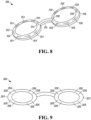
- FIGS. 7 -9 illustrate different example ocular bioimpedance devices and configurations.
- FIG. 7 illustrates an example ocular bioimpedance device 100 in the form of goggles having a first lens 102 formed of a cap that may transparent, partially transparent or opaque.
- the first lens 102 further includes one or more electrodes 104, shown in FIG. 8 , on an interior ocular region engagement portion of the lens 102.
- the engagement portion is configured such that when the lens 102 is put in place on a subject, the one or more electrodes 104 are in conductive contact with surface skin of the subject.
- the one or more electrodes 104 provides a conduction path to the skin for injecting current to the subject at a point of contact within and thus through the skin of the ocular region of the subject.
- That conductive contact may be a direct contact with the skin (such as the close eyelids), such that the point of contact with the electrodes 104 is direct, or that point of contact may be through another electrical conductor positioned between the electrodes 104 and the skin, for example, through a conductive film positioned on or around the ocular region for dispersing the electrical current more uniformly to the patient.
- the device 100 includes a second lens 106 that may be similar or identical to the first lens 102 except that the electrodes in the second lens 106 may be configured for sensing the injected current from the first lens and thereby being used as a bioimpedance sensor. Electrodes 108 of the second lens 106 may be in direct contact with the skin or in indirect contact, like that of the electrodes 104.
- the electrical current path is described as starting with lens 102 and terminating with lens 106, such orientation may be imposed by the control circuitry coupled thereto (see, e.g., FIG. 10 ).
- the control circuitry could reverse the current flow direction and the operation would be the same.
- the electrodes 104 and 108 are not identical, but may differ in electrode pattern and/or positioning. In such examples, the particular direction of current injection and sensing may be established, at least in part, based on the differences in those electrodes.
- the lens 102 and 106 are physically connected by a bridge 110 formed for a non-conducting material to further provide proper electrical isolation of the electrodes 104 and 108.
- FIG. 9 illustrates another example configuration of an ocular bioimpedance device 200 similarly formed of a first lens 202 and a second lens 204.
- each lens includes both injection electrodes 206 and sensing electrodes 208.
- the patterning of the electrodes 206 and 208 can vary in pattern and position, as well.
- the injection electrodes 206 are disposed closer to a centroid of each lens 202 and 204, while the sensing electrodes 208 are positioned distally further from the centroid.
- the converse orientation may be used instead.
- the electrodes 206 and 208 may be positioned in an alternating manner around the engagement surface of the lens. As is the case for the device 100, in some examples, only one of each electrode type is used on each lens.
- contact is achieved between the corneal tissue and the device in a contact lens type manner.
- lens-based devices for measuring bioimpedance may be combined with lens based devices and also include light transmitters in the lens cap, transmitters that are able to provide light therapy to a patient, such as goggles that provide white light therapy through light emitting diodes (LEDs), high color temperature light therapy (500 lux, 1000 lux, 1500 lux, or higher), blue light therapy devices (e.g., emitting at wavelengths at or between 450 nm and 500 nm), various near infrared and infrared wavelengths (730-770 nm, 850-890 nm, 880-920 nm, 950-970 nm) for cerebral blood oxygenation monitoring, mitochondrial repair, and others.
- LEDs light emitting diodes
- high color temperature light therapy 500 lux, 1000 lux, 1500 lux, or higher
- blue light therapy devices e.g., emitting at wavelengths at or between 450 nm and 500 nm
- various near infrared and infrared wavelengths (730-770
- the ocular bioimpedance techniques herein may be used with an acoustic energy application device, such as that described in U.S. Patent No. 8,172,769 , entitled “Method and apparatus for monitoring intra ocular and intra cranial pressure,” the entire specification of which is hereby incorporated by reference.
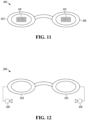
- FIG. 11 illustrates an ocular treatment device 400 having a lens 402 and a lens 406, each embedded with a photonic treatment LED array 410 and 412, respectively.
- the LED arrays 410 and 412 may be positioned over centralized portion of the cap forming the lens 402 and 406.
- These caps may be opaque blocking external light from impinging upon the subject. Instead, for these examples, only photons from the arrays 410 and 412 would imping upon the subject.
- the lens described herein may be transparent or semi-transparent (i.e., translucent).
- the arrays 410 and 412 generate photonic stimulation thereby providing therapy to the subject and/or diagnostic information to the subject, via this integrated goggle configuration.
- the device 400 may be controlled by a controller, an example of which is described in FIG. 10 , that controls both photonic stimulation and electrical signals.
- the photonic stimulation may be provided during supply of an electrical signal applied and sensed through electrodes (not shown) that may be positioned at the lens rim for ocular region contact, as shown in the examples of Figs. 8 and 9 .
- the electrodes (not shown) would provide electrical signals for sensing bioimpedance and/or for treating the subject.
- the photonic stimulation signals do not overlap with the supply of the electrical signal.
- FIG. 12 illustrates a device 500 having lens 502 and 504 and integrated with an acoustic stimulation stage formed by two speakers 506 that are configured to provide acoustic stimulation for therapeutic or diagnostic purposes to the subject.
- the speakers may be ear-plug styled headphones, over the ear headphones, miniature speakers attached to side of the subject or near the ocular region, including near or at a subject's temple, etc. That is, the speakers 506 may be configured to provide the acoustic stimulation at the ocular region and/or at a region on the subject other than the ocular region.
- Electrodes would provide electrical signals for sensing bioimpedance and/or for treating the subject.
- a controller like that of Fig. 10 would be used to control both electrical signals and acoustic stimulation signals.
- FIG. 10 is an example block diagram 300 illustrating the various components used in implementing an example embodiment of the ocular bioimpedance measuring techniques herein.
- An analysis apparatus 302 is coupled to a patient 320 (e.g., a human or animal) via an ocular bioimpedance device 316 in accordance with executing the functions of the disclosed embodiments, and more specifically by current injecting electrodes 350 electrically coupled to the ocular region of the patient 320 and sensing electrodes 352 also electrically coupled to the ocular region of the patient 320.
- the analysis apparatus 302 may have a controller 304 operatively connected to the database 314 via a link 322 connected to an input/output (I/O) circuit 312.
- I/O input/output
- the controller 304 includes a program memory 306, the processor 308 (may be called a microcontroller or a microprocessor), a random-access memory (RAM) 310, and the input/output (I/O) circuit 312, all of which are interconnected via an address/data bus 320. It should be appreciated that although only one microprocessor 308 is shown, the controller 304 may include multiple microprocessors 308. Similarly, the memory of the controller 304 may include multiple RAMs 310 and multiple program memories 306.
- the program memory 306 and/or the RAM 310 may store various applications (i.e., machine readable instructions) for execution by the microprocessor 308.
- applications i.e., machine readable instructions
- an operating system 330 may generally control the operation of the testing apparatus 302 and provide a user interface to the testing apparatus 302 to implement the processes described herein.
- the program memory 306 and/or the RAM 310 may also store a variety of subroutines 332 for accessing specific functions of the testing apparatus 302.
- the subroutines 332 may include, among other things: a subroutine for providing electrical current to the ocular region, a subroutine for taking bioimpedance measurements with the ocular bioimpedance device 316, a subroutine for determining a brain health indicator such as MAP, ICP, CBF, CPP, and ocular-brain impedance, and other subroutines, for example, implementing software keyboard functionality, interfacing with other hardware in the analysis apparatus 302, etc.
- the processes described hereinabove may be stored on the program memory 306 for execution by the processor 308.
- the program memory 306 and/or the RAM 310 may further store data related to the configuration and/or operation of the analysis apparatus 302, and/or related to the operation of one or more subroutines 252.
- the data may be data gathered by the ocular bioimpedance device 316, data determined and/or calculated by the processor 308, etc.
- the analysis apparatus 302 may include other hardware resources.
- the analysis apparatus 302 may also include various types of input/output hardware such as a visual display 326 and input device(s) 328 (e.g., keypad, keyboard, etc.).
- the display 326 is touch-sensitive, and may cooperate with a software keyboard routine as one of the software routines 332 to accept user input.
- the analysis apparatus may communicate with a broader medical treatment network (not shown) through any of a number of known networking devices and techniques (e.g., through a commuter network such as a hospital or clinic intranet, the Internet, etc.).
- the analysis apparatus may be connected to a medical records database, hospital management processing system, health care professional terminals (e.g., doctor stations, nurse stations), patient monitoring systems, automated drug delivery systems such as smart pumps, smart infusion systems, automated drug delivery systems, etc.
- the disclosed embodiments may be used as part of an automated closed loop system or as part of a decision assist system.
- a network interface 334 is coupled to the I/O interface 312 for connecting the analysis apparatus 302 to a network 336, through a wired or wireless connection.
- the system 300 may be configured to determine the bioimpedance of the patient and then further assess brain health, by determining, for example, whether the bioimpedance changes over time, changes in response to treatment, or changes based on some other conditions.
- the system 300 is configured to determine brain health indicators such as MAP, ICP, CBF, CPP, and/or ocular-brain impedance and measure the same over time.
- changes in brain impedance can be used to titrate specific therapies such as MAP, ventilation parameters, ICP (through removal of cerebral spinal fluid), blood and fluid transfusions in order to optimize CPP and preserve CAR to improve cerebral outcomes.
- decreases in brain impedance in response to a rising MAP may prompt health care providers to reduce MAP.
- Another example may include an increase in impedance with no change in MAP or current care may indicate a rise in ICP thus prompting therapies to reduce ICP.
- bioimpedance determination techniques herein are combined with treatment techniques to improve the efficacy of such treatments.
- transcranial direct current stimulation has been proposed as a neuromodulation technique in the treatment of psychiatric illnesses, such as depression or schizophrenia, as well as in providing cognitive enhancement, such as memory enhancement, executive function enhancement, attention enhancement, and fluency enhancement.
- the techniques can include applying direct current stimulation to the brain through the use of electrodes externally placed on the skin at various locations on the scalp.
- the amount of current that actually penetrates the scalp and flows into the brain is believed to be very small.
- electrodes in the ocular region it is now possible to deliver higher levels of current to the brain as outlined in the previously described experiments where ocular versus scalp pathways were compared in their ability to penetrate into the brain.
- This ocular pathway for delivery of direct current may be coupled with the simultaneous or intermittent measuring of brain bioimpedance in accordance with the present techniques as a means to help monitor therapy, as desired.
- This bioimpedance-based feedback can then be used to further guide the treatment, either manually or through completely- or partially-automated computer processing of the treatment signal.
- the transcranial direct current stimulation controller that controls the electrical stimulation signals sent to the brain can be configured to automatically re-adjust the electrical signals (i.e., current value, frequency, waveform, voltage, etc.) in response to changes in the enhanced PRx, e.g., from the PRx changing from a negative value to a positive value.
- traditional tDCS using the scalp as the site of current injection may be directed by using the ocular-brain bioimpedance signal to optimize the location of the tDCS electrodes.
- tDCS electrodes may be positioned on a subject and a treatment is commenced. The bioimpedance is measured; and the electrodes are placed at another location, from which the bioimpedance is re-measured.
- a treatment professional can determine which tDCS electrode location is better for treating the subject, for example, which location results in the better brain health indicator value.
- ocular-brain region bioimpedance enhanced treatment techniques are not limited to tDCS.
- the techniques can be used in a similar manner with transcranial alternating current stimulation (tACS) to control stimulation signal characteristics, the location of the tACS stimulation electrodes, etc.
- tACS is used similar to tDCS for numerous neuro- and neuro-psychiatric conditions ranging from stroke to depression.
- the ocular-brain pathway techniques herein may be used to both deliver tACS and/or tDCS as well as monitor brain bioimpedance in addition to the ocular-brain pathway of bioimpedance being used to optimize scalp electrode placement for tDCS and tACS.
- these ocular-brain bioimpedance enhanced treatments may include biophotonic-based treatments and acoustic-based treatments.
- Biophotonic treatments include proton photonic stimulation to a subject and monitoring the effects thereof. These biophotonic treatments include what is commonly referred to as red light therapy, blue light therapy, infrared therapy, where stimulation photons are provided through the vision system of a subject.
- the bioimpedance techniques described herein may be used to monitor the effectiveness of biophotonic therapy by measuring, for example, a brain health indicator during treatment and assessing the effectiveness of that treatment in response.
- Acoustic-based treatments may be analyzed in a similar manner.
- acoustic energy is applied to the head of a subject to detect increases in intracranial pressure.
- Acoustic eye patches for example, are applied to a patient's eye or eyelid, and an ultrasonic sweep generator applies an acoustic signal across the patient's skull, the signal being swept across a predetermined range.
- the eye patches have piezoelectric film sensors for measuring the acoustic signal.
- the predetermined range is in the ultrasonic band and an analyzer determines from the output of the sensors a resonant frequency and a damping of acoustic amplitude at said resonant frequency, there being a correlation between said damping and intra cranial pressure.
- the predetermined range includes a range less than 20 kHz and the analyzer determines retinal artery pulsations, with pressure being applied to the eye until the pulsations disappear, such pressure being a measure of intra cranial pressure.
- These acoustic eye patches are configured with bioimpedance electrodes that measure the ocular-brain region bioimpedance of the subject during application of the acoustic signal. The effectiveness of the acoustic signals may then be assessed based on the changes in the bioimpedance values or brain health indicator(s) derived therefrom. And, as is the case with the other treatment examples herein (tDCS, tACS, biophotonics, etc.), the treatment signals may be adjusted to improve brain health based on the measured bioimpedance response.
- routines, subroutines, applications, or instructions may constitute either software (e.g., code embodied on a machine-readable medium or in a transmission signal) or hardware.
- routines, etc. are tangible units capable of performing certain operations and may be configured or arranged in a certain manner.
- one or more computer systems e.g., a standalone, client or server computer system
- one or more hardware modules of a computer system e.g., a processor or a group of processors
- software e.g., an application or application portion
- a hardware module may be implemented mechanically or electronically.
- a hardware module may comprise dedicated circuitry or logic that is permanently configured (e.g., as a special-purpose processor, such as a field programmable gate array (FPGA) or an application-specific integrated circuit (ASIC)) to perform certain operations.
- a hardware module may also comprise programmable logic or circuitry (e.g., as encompassed within a general-purpose processor or other programmable processor) that is temporarily configured by software to perform certain operations. It will be appreciated that the decision to implement a hardware module mechanically, in dedicated and permanently configured circuitry, or in temporarily configured circuitry (e.g., configured by software) may be driven by cost and time considerations.
- the term "hardware module” should be understood to encompass a tangible entity, be that an entity that is physically constructed, permanently configured (e.g., hardwired), or temporarily configured (e.g., programmed) to operate in a certain manner or to perform certain operations described herein.
- hardware modules are temporarily configured (e.g., programmed)
- each of the hardware modules need not be configured or instantiated at any one instance in time.
- the hardware modules comprise a general-purpose processor configured using software
- the general-purpose processor may be configured as respective different hardware modules at different times.
- Software may accordingly configure a processor, for example, to constitute a particular hardware module at one instance of time and to constitute a different hardware module at a different instance of time.
- Hardware modules can provide information to, and receive information from, other hardware modules. Accordingly, the described hardware modules may be regarded as being communicatively coupled. Where multiple of such hardware modules exist contemporaneously, communications may be achieved through signal transmission (e.g., over appropriate circuits and buses) that connects the hardware modules. In embodiments in which multiple hardware modules are configured or instantiated at different times, communications between such hardware modules may be achieved, for example, through the storage and retrieval of information in memory structures to which the multiple hardware modules have access. For example, one hardware module may perform an operation and store the output of that operation in a memory device to which it is communicatively coupled. A further hardware module may then, at a later time, access the memory device to retrieve and process the stored output. Hardware modules may also initiate communications with input or output devices, and can operate on a resource (e.g., a collection of information).
- a resource e.g., a collection of information
- processors may be temporarily configured (e.g., by software) or that are permanently configured to perform the relevant operations. Whether temporarily or permanently configured, such processors may constitute processor-implemented modules that operate to perform one or more operations or functions.
- the modules referred to herein may, in some example embodiments, comprise processor-implemented modules.
- the methods or routines described herein may be at least partially processor-implemented. For example, at least some of the operations of a method may be performed by one or more processors or by processor-implemented hardware modules. The performance of certain of the operations may be distributed among the one or more processors, not only residing within a single machine (having different processing abilities), but also deployed across a number of machines. In some example embodiments, the processors may be located in a single location (e.g., deployed in the field, in an office environment, or as part of a server farm), while in other embodiments the processors may be distributed across a number of locations.
- any reference to "one embodiment” or “an embodiment” means that a particular element, feature, structure, or characteristic described in connection with the embodiment is included in at least one embodiment.
- the appearances of the phrase “in one embodiment” in various places in the specification are not necessarily all referring to the same embodiment.
- Coupled and “connected” along with their derivatives.
- some embodiments may be described using the term “coupled” to indicate that two or more elements are in direct physical or electrical contact.
- the term “coupled,” however, may also mean that two or more elements are not in direct contact with each other, but yet still co-operate or interact with each other.
- the embodiments are not limited in this context.
- the terms “comprises,” “comprising,” “includes,” “including,” “has,” “having” or any other variation thereof, are intended to cover a non-exclusive inclusion.
- a process, method, article, or apparatus that comprises a list of elements is not necessarily limited to only those elements but may include other elements not expressly listed or inherent to such process, method, article, or apparatus.
- “or” refers to an inclusive or and not to an exclusive or. For example, a condition A or B is satisfied by any one of the following: A is true (or present) and B is false (or not present), A is false (or not present) and B is true (or present), and both A and B are true (or present).
Landscapes
- Health & Medical Sciences (AREA)
- Life Sciences & Earth Sciences (AREA)
- Public Health (AREA)
- Engineering & Computer Science (AREA)
- Biomedical Technology (AREA)
- Veterinary Medicine (AREA)
- Animal Behavior & Ethology (AREA)
- General Health & Medical Sciences (AREA)
- Heart & Thoracic Surgery (AREA)
- Biophysics (AREA)
- Molecular Biology (AREA)
- Physics & Mathematics (AREA)
- Pathology (AREA)
- Medical Informatics (AREA)
- Surgery (AREA)
- Neurology (AREA)
- Radiology & Medical Imaging (AREA)
- Nuclear Medicine, Radiotherapy & Molecular Imaging (AREA)
- Physiology (AREA)
- Neurosurgery (AREA)
- Psychology (AREA)
- Pulmonology (AREA)
- Hematology (AREA)
- Cardiology (AREA)
- Developmental Disabilities (AREA)
- Hospice & Palliative Care (AREA)
- Psychiatry (AREA)
- Social Psychology (AREA)
- Child & Adolescent Psychology (AREA)
- Measurement And Recording Of Electrical Phenomena And Electrical Characteristics Of The Living Body (AREA)
- Measurement Of The Respiration, Hearing Ability, Form, And Blood Characteristics Of Living Organisms (AREA)
- Measuring And Recording Apparatus For Diagnosis (AREA)
Applications Claiming Priority (3)
| Application Number | Priority Date | Filing Date | Title |
|---|---|---|---|
| US201762506971P | 2017-05-16 | 2017-05-16 | |
| PCT/US2018/032984 WO2018213456A1 (en) | 2017-05-16 | 2018-05-16 | Ocular impedance-based system for brain health monitoring |
| EP18801715.6A EP3624890B1 (de) | 2017-05-16 | 2018-05-16 | Augenimpedanzbasiertes system zur überwachung der hirngesundheit |
Related Parent Applications (1)
| Application Number | Title | Priority Date | Filing Date |
|---|---|---|---|
| EP18801715.6A Division EP3624890B1 (de) | 2017-05-16 | 2018-05-16 | Augenimpedanzbasiertes system zur überwachung der hirngesundheit |
Publications (3)
| Publication Number | Publication Date |
|---|---|
| EP4403206A2 true EP4403206A2 (de) | 2024-07-24 |
| EP4403206A3 EP4403206A3 (de) | 2024-10-16 |
| EP4403206B1 EP4403206B1 (de) | 2025-09-10 |
Family
ID=64274876
Family Applications (2)
| Application Number | Title | Priority Date | Filing Date |
|---|---|---|---|
| EP24180772.6A Active EP4403206B1 (de) | 2017-05-16 | 2018-05-16 | Augenimpedanzbasiertes system zur überwachung der gehirngesundheit |
| EP18801715.6A Active EP3624890B1 (de) | 2017-05-16 | 2018-05-16 | Augenimpedanzbasiertes system zur überwachung der hirngesundheit |
Family Applications After (1)
| Application Number | Title | Priority Date | Filing Date |
|---|---|---|---|
| EP18801715.6A Active EP3624890B1 (de) | 2017-05-16 | 2018-05-16 | Augenimpedanzbasiertes system zur überwachung der hirngesundheit |
Country Status (5)
| Country | Link |
|---|---|
| US (2) | US11484217B2 (de) |
| EP (2) | EP4403206B1 (de) |
| JP (2) | JP2020520699A (de) |
| CN (1) | CN110753567A (de) |
| WO (1) | WO2018213456A1 (de) |
Families Citing this family (7)
| Publication number | Priority date | Publication date | Assignee | Title |
|---|---|---|---|---|
| US11406558B2 (en) | 2016-04-25 | 2022-08-09 | Preactive Technologies Inc. | Reducing brain injury by limiting brain motion during sudden deceleration or acceleration of the head |
| US12041997B2 (en) | 2016-04-25 | 2024-07-23 | Preactive Technologies Inc. | Reducing brain injury by limiting brain motion during sudden deceleration or acceleration of the head |
| EP3934529A4 (de) * | 2019-03-05 | 2022-11-09 | Baylor College of Medicine | Vorrichtungen und verfahren zur messung des gehirnzustandes |
| CN116919713A (zh) * | 2022-04-06 | 2023-10-24 | 珠海格力电器股份有限公司 | 一种眼部按摩仪、眼部按摩仪的控制方法及装置 |
| WO2025053635A1 (ko) * | 2023-09-08 | 2025-03-13 | (주)메그노시스 | 질병 진단 장치 및 방법 |
| CN120037578B (zh) * | 2025-02-21 | 2025-11-11 | 北京领创医谷科技发展有限责任公司 | 用于测量电极阻抗的系统和方法以及评估电极健康度的方法 |
| CN120183598B (zh) * | 2025-05-21 | 2025-09-16 | 中国人民解放军总医院第一医学中心 | 基于循证的偏头痛风险指标构建系统 |
Citations (1)
| Publication number | Priority date | Publication date | Assignee | Title |
|---|---|---|---|---|
| US8172769B2 (en) | 2003-08-08 | 2012-05-08 | Virginia Commonwealth University | Method and apparatus for monitoring intra ocular and intra cranial pressure |
Family Cites Families (19)
| Publication number | Priority date | Publication date | Assignee | Title |
|---|---|---|---|---|
| US4771784A (en) | 1987-02-17 | 1988-09-20 | Kuibyshevksy Politekhnichesky Institut | Ophthalmorheographic transducer |
| JPH073444B2 (ja) | 1987-10-27 | 1995-01-18 | 株式会社日本システム研究所 | 導電性測定装置 |
| US5360971A (en) * | 1992-03-31 | 1994-11-01 | The Research Foundation State University Of New York | Apparatus and method for eye tracking interface |
| US5726916A (en) * | 1996-06-27 | 1998-03-10 | The United States Of America As Represented By The Secretary Of The Army | Method and apparatus for determining ocular gaze point of regard and fixation duration |
| US7998080B2 (en) * | 2002-01-15 | 2011-08-16 | Orsan Medical Technologies Ltd. | Method for monitoring blood flow to brain |
| US7158834B2 (en) * | 2002-06-13 | 2007-01-02 | Atlantic Medical, Inc. | Method and apparatus for performing microcurrent stimulation (MSC) therapy |
| WO2004082460A2 (en) | 2003-03-14 | 2004-09-30 | Shock, Llc | Methods of and apparatus for determining fluid volume presence in mammalian tissue |
| US20070167694A1 (en) * | 2005-12-21 | 2007-07-19 | Everest Biomedical Instruments Co. | Integrated Portable Anesthesia and Sedation Monitoring Apparatus |
| US9623241B2 (en) | 2006-06-19 | 2017-04-18 | Highland Instruments | Treatment methods |
| JP4945644B2 (ja) * | 2006-12-22 | 2012-06-06 | エーベーエス テヒノロギーズ ゲーエムベーハー | ヒトの脳を刺激する装置 |
| US9827210B2 (en) * | 2007-06-29 | 2017-11-28 | Phovitreal Pty Ltd | Treatment or prophylaxis of a neurological or neuropsychiatric disorders via ocular administration |
| WO2010004698A1 (ja) * | 2008-07-11 | 2010-01-14 | パナソニック株式会社 | 脳波を用いた機器の制御方法および脳波インタフェースシステム |
| US7744541B2 (en) | 2008-07-29 | 2010-06-29 | Raba Equity Partners Ii, Llc | Cerebral vascular reactivity monitoring |
| WO2013112687A1 (en) * | 2012-01-25 | 2013-08-01 | Baruch Robert A | Autoregulation monitoring |
| KR101318987B1 (ko) * | 2013-02-18 | 2013-10-16 | 강원대학교산학협력단 | 고글형 미세 전류 치료 장치 |
| AU2014225626B2 (en) * | 2013-03-06 | 2018-02-15 | Cerora, Inc. | Form factors for the multi-modal physiological assessment of brain health |
| US10365716B2 (en) * | 2013-03-15 | 2019-07-30 | Interaxon Inc. | Wearable computing apparatus and method |
| WO2014167418A2 (en) * | 2013-04-12 | 2014-10-16 | Shlomi Ben-Ari | Measurement of cerebral physiologic parameters using bioimpedance |
| PL224517B1 (pl) * | 2013-09-03 | 2017-01-31 | Silvermedia Spółka Z Ograniczoną Odpowiedzialnością | System rejestracji i obróbki sygnałów do diagnostyki układu słuchowego i sposób rejestracji i obróbki sygnałów do diagnostyki układu słuchowego |
-
2018
- 2018-05-16 JP JP2019563423A patent/JP2020520699A/ja active Pending
- 2018-05-16 EP EP24180772.6A patent/EP4403206B1/de active Active
- 2018-05-16 WO PCT/US2018/032984 patent/WO2018213456A1/en not_active Ceased
- 2018-05-16 CN CN201880038604.1A patent/CN110753567A/zh active Pending
- 2018-05-16 EP EP18801715.6A patent/EP3624890B1/de active Active
- 2018-05-16 US US16/613,707 patent/US11484217B2/en active Active
-
2022
- 2022-10-31 US US17/976,970 patent/US20230157563A1/en active Pending
-
2023
- 2023-11-16 JP JP2023195404A patent/JP2024014970A/ja active Pending
Patent Citations (1)
| Publication number | Priority date | Publication date | Assignee | Title |
|---|---|---|---|---|
| US8172769B2 (en) | 2003-08-08 | 2012-05-08 | Virginia Commonwealth University | Method and apparatus for monitoring intra ocular and intra cranial pressure |
Also Published As
| Publication number | Publication date |
|---|---|
| EP3624890A1 (de) | 2020-03-25 |
| CN110753567A (zh) | 2020-02-04 |
| EP3624890A4 (de) | 2021-02-24 |
| US20230157563A1 (en) | 2023-05-25 |
| WO2018213456A1 (en) | 2018-11-22 |
| US11484217B2 (en) | 2022-11-01 |
| EP3624890B1 (de) | 2024-06-19 |
| JP2020520699A (ja) | 2020-07-16 |
| EP4403206B1 (de) | 2025-09-10 |
| US20210169362A1 (en) | 2021-06-10 |
| JP2024014970A (ja) | 2024-02-01 |
| EP4403206A3 (de) | 2024-10-16 |
Similar Documents
| Publication | Publication Date | Title |
|---|---|---|
| US20230157563A1 (en) | Ocular impedance-based system for brain health monitoring | |
| US12427312B2 (en) | Transcranial stimulation device and method based on electrophysiological testing | |
| AU2017235723B2 (en) | Sleep apnea monitoring system | |
| JP5956618B2 (ja) | マルチモーダルデータを使用する発作検出、定量化及び/又は分類 | |
| US12213770B2 (en) | Portable device for quantitative measurement of tissue autoregulation and neurovascular coupling using EEG, metabolism, and blood flow diagnostics | |
| US20120316451A1 (en) | Event Evaluation Using Heart Rate Variation for Ingestion Monitoring and Therapy | |
| CN112244792A (zh) | 多维应激管理系统及方法 | |
| US12588861B2 (en) | Wearable device and method for non-invasive assessment of glymphatic flow | |
| WO2024081881A1 (en) | Method and device to enhance waste clearance in the brain | |
| CN107041747B (zh) | 一种用于脊柱整复系统的呼吸指示装置 | |
| Litscher | Integrative Laser Medicine and High‐Tech Acupuncture at the Medical University of Graz, Austria, Europe | |
| CN107041750A (zh) | 一种用于脊柱整复系统的经颅磁刺激装置 | |
| WO2021142518A1 (pt) | Processo e sistema de ativação e monitorização neuromuscular artificial baseado em inteligência artificial | |
| US20250134405A1 (en) | Portable device for quantitative measurement of tissue autoregulation and neurovascular coupling using eeg, metabolism, and blood flow diagnostics | |
| CN107041746A (zh) | 一种用于脊柱整复系统的磁疗装置 | |
| CN107041748A (zh) | 一种用于脊柱整复系统心电触发磁疗装置 | |
| CN114585301B (zh) | 用于检测对象头部血流变化的方法和设备 | |
| CN113456484B (zh) | 基于多生理信号融合实时监测的针灸刺激评估方法及系统 | |
| US20240293664A1 (en) | Therapeutic electrical muscle stimulation apparatus and method of treatment | |
| WO2025019750A2 (en) | Flexible dynamic optical spectroscopic systems, devices, and methods for cardiovascular monitoring, tomography and diffuse optical imaging | |
| CN120690371A (zh) | 一种基于生物反馈的神经源性膀胱-焦虑协同调控辅助系统 |
Legal Events
| Date | Code | Title | Description |
|---|---|---|---|
| PUAI | Public reference made under article 153(3) epc to a published international application that has entered the european phase |
Free format text: ORIGINAL CODE: 0009012 |
|
| STAA | Information on the status of an ep patent application or granted ep patent |
Free format text: STATUS: THE APPLICATION HAS BEEN PUBLISHED |
|
| AC | Divisional application: reference to earlier application |
Ref document number: 3624890 Country of ref document: EP Kind code of ref document: P |
|
| AK | Designated contracting states |
Kind code of ref document: A2 Designated state(s): AL AT BE BG CH CY CZ DE DK EE ES FI FR GB GR HR HU IE IS IT LI LT LU LV MC MK MT NL NO PL PT RO RS SE SI SK SM TR |
|
| REG | Reference to a national code |
Ref country code: DE Ref legal event code: R079 Free format text: PREVIOUS MAIN CLASS: A61N0001080000 Ipc: A61N0001360000 Ref document number: 602018085615 Country of ref document: DE |
|
| PUAL | Search report despatched |
Free format text: ORIGINAL CODE: 0009013 |
|
| AK | Designated contracting states |
Kind code of ref document: A3 Designated state(s): AL AT BE BG CH CY CZ DE DK EE ES FI FR GB GR HR HU IE IS IT LI LT LU LV MC MK MT NL NO PL PT RO RS SE SI SK SM TR |
|
| RIC1 | Information provided on ipc code assigned before grant |
Ipc: A61B 5/03 20060101ALN20240909BHEP Ipc: A61B 5/026 20060101ALN20240909BHEP Ipc: A61N 1/04 20060101ALI20240909BHEP Ipc: A61N 1/08 20060101ALI20240909BHEP Ipc: A61N 1/05 20060101ALI20240909BHEP Ipc: A61B 5/053 20210101ALI20240909BHEP Ipc: A61N 1/37 20060101ALI20240909BHEP Ipc: A61N 1/362 20060101ALI20240909BHEP Ipc: A61B 5/00 20060101ALI20240909BHEP Ipc: A61N 1/36 20060101AFI20240909BHEP |
|
| STAA | Information on the status of an ep patent application or granted ep patent |
Free format text: STATUS: REQUEST FOR EXAMINATION WAS MADE |
|
| 17P | Request for examination filed |
Effective date: 20250219 |
|
| GRAP | Despatch of communication of intention to grant a patent |
Free format text: ORIGINAL CODE: EPIDOSNIGR1 |
|
| STAA | Information on the status of an ep patent application or granted ep patent |
Free format text: STATUS: GRANT OF PATENT IS INTENDED |
|
| INTG | Intention to grant announced |
Effective date: 20250408 |
|
| RIC1 | Information provided on ipc code assigned before grant |
Ipc: A61B 5/03 20060101ALN20250401BHEP Ipc: A61B 5/026 20060101ALN20250401BHEP Ipc: A61N 1/04 20060101ALI20250401BHEP Ipc: A61N 1/08 20060101ALI20250401BHEP Ipc: A61N 1/05 20060101ALI20250401BHEP Ipc: A61B 5/053 20210101ALI20250401BHEP Ipc: A61N 1/37 20060101ALI20250401BHEP Ipc: A61N 1/362 20060101ALI20250401BHEP Ipc: A61B 5/00 20060101ALI20250401BHEP Ipc: A61N 1/36 20060101AFI20250401BHEP |
|
| GRAS | Grant fee paid |
Free format text: ORIGINAL CODE: EPIDOSNIGR3 |
|
| GRAA | (expected) grant |
Free format text: ORIGINAL CODE: 0009210 |
|
| STAA | Information on the status of an ep patent application or granted ep patent |
Free format text: STATUS: THE PATENT HAS BEEN GRANTED |
|
| AC | Divisional application: reference to earlier application |
Ref document number: 3624890 Country of ref document: EP Kind code of ref document: P |
|
| AK | Designated contracting states |
Kind code of ref document: B1 Designated state(s): AL AT BE BG CH CY CZ DE DK EE ES FI FR GB GR HR HU IE IS IT LI LT LU LV MC MK MT NL NO PL PT RO RS SE SI SK SM TR |
|
| REG | Reference to a national code |
Ref country code: GB Ref legal event code: FG4D |
|
| REG | Reference to a national code |
Ref country code: CH Ref legal event code: EP |
|
| REG | Reference to a national code |
Ref country code: DE Ref legal event code: R096 Ref document number: 602018085615 Country of ref document: DE |
|
| REG | Reference to a national code |
Ref country code: IE Ref legal event code: FG4D |
|
| PG25 | Lapsed in a contracting state [announced via postgrant information from national office to epo] |
Ref country code: NO Free format text: LAPSE BECAUSE OF FAILURE TO SUBMIT A TRANSLATION OF THE DESCRIPTION OR TO PAY THE FEE WITHIN THE PRESCRIBED TIME-LIMIT Effective date: 20251210 |
|
| REG | Reference to a national code |
Ref country code: LT Ref legal event code: MG9D |
|
| PG25 | Lapsed in a contracting state [announced via postgrant information from national office to epo] |
Ref country code: FI Free format text: LAPSE BECAUSE OF FAILURE TO SUBMIT A TRANSLATION OF THE DESCRIPTION OR TO PAY THE FEE WITHIN THE PRESCRIBED TIME-LIMIT Effective date: 20250910 |
|
| REG | Reference to a national code |
Ref country code: NL Ref legal event code: MP Effective date: 20250910 |
|
| PG25 | Lapsed in a contracting state [announced via postgrant information from national office to epo] |
Ref country code: HR Free format text: LAPSE BECAUSE OF FAILURE TO SUBMIT A TRANSLATION OF THE DESCRIPTION OR TO PAY THE FEE WITHIN THE PRESCRIBED TIME-LIMIT Effective date: 20250910 |
|
| PG25 | Lapsed in a contracting state [announced via postgrant information from national office to epo] |
Ref country code: GR Free format text: LAPSE BECAUSE OF FAILURE TO SUBMIT A TRANSLATION OF THE DESCRIPTION OR TO PAY THE FEE WITHIN THE PRESCRIBED TIME-LIMIT Effective date: 20251211 |
|
| PG25 | Lapsed in a contracting state [announced via postgrant information from national office to epo] |
Ref country code: SE Free format text: LAPSE BECAUSE OF FAILURE TO SUBMIT A TRANSLATION OF THE DESCRIPTION OR TO PAY THE FEE WITHIN THE PRESCRIBED TIME-LIMIT Effective date: 20250910 |
|
| PG25 | Lapsed in a contracting state [announced via postgrant information from national office to epo] |
Ref country code: LV Free format text: LAPSE BECAUSE OF FAILURE TO SUBMIT A TRANSLATION OF THE DESCRIPTION OR TO PAY THE FEE WITHIN THE PRESCRIBED TIME-LIMIT Effective date: 20250910 |
|
| PG25 | Lapsed in a contracting state [announced via postgrant information from national office to epo] |
Ref country code: PL Free format text: LAPSE BECAUSE OF FAILURE TO SUBMIT A TRANSLATION OF THE DESCRIPTION OR TO PAY THE FEE WITHIN THE PRESCRIBED TIME-LIMIT Effective date: 20250910 Ref country code: BG Free format text: LAPSE BECAUSE OF FAILURE TO SUBMIT A TRANSLATION OF THE DESCRIPTION OR TO PAY THE FEE WITHIN THE PRESCRIBED TIME-LIMIT Effective date: 20250910 |
|
| PG25 | Lapsed in a contracting state [announced via postgrant information from national office to epo] |
Ref country code: RS Free format text: LAPSE BECAUSE OF FAILURE TO SUBMIT A TRANSLATION OF THE DESCRIPTION OR TO PAY THE FEE WITHIN THE PRESCRIBED TIME-LIMIT Effective date: 20251210 |
|
| PG25 | Lapsed in a contracting state [announced via postgrant information from national office to epo] |
Ref country code: ES Free format text: LAPSE BECAUSE OF FAILURE TO SUBMIT A TRANSLATION OF THE DESCRIPTION OR TO PAY THE FEE WITHIN THE PRESCRIBED TIME-LIMIT Effective date: 20250910 |
|
| REG | Reference to a national code |
Ref country code: AT Ref legal event code: MK05 Ref document number: 1835271 Country of ref document: AT Kind code of ref document: T Effective date: 20250910 |
|
| PG25 | Lapsed in a contracting state [announced via postgrant information from national office to epo] |
Ref country code: NL Free format text: LAPSE BECAUSE OF FAILURE TO SUBMIT A TRANSLATION OF THE DESCRIPTION OR TO PAY THE FEE WITHIN THE PRESCRIBED TIME-LIMIT Effective date: 20250910 |
|
| PG25 | Lapsed in a contracting state [announced via postgrant information from national office to epo] |
Ref country code: SM Free format text: LAPSE BECAUSE OF FAILURE TO SUBMIT A TRANSLATION OF THE DESCRIPTION OR TO PAY THE FEE WITHIN THE PRESCRIBED TIME-LIMIT Effective date: 20250910 |
|
| PGFP | Annual fee paid to national office [announced via postgrant information from national office to epo] |
Ref country code: GB Payment date: 20260326 Year of fee payment: 9 |
|
| PG25 | Lapsed in a contracting state [announced via postgrant information from national office to epo] |
Ref country code: AT Free format text: LAPSE BECAUSE OF FAILURE TO SUBMIT A TRANSLATION OF THE DESCRIPTION OR TO PAY THE FEE WITHIN THE PRESCRIBED TIME-LIMIT Effective date: 20250910 |
|
| PG25 | Lapsed in a contracting state [announced via postgrant information from national office to epo] |
Ref country code: IT Free format text: LAPSE BECAUSE OF FAILURE TO SUBMIT A TRANSLATION OF THE DESCRIPTION OR TO PAY THE FEE WITHIN THE PRESCRIBED TIME-LIMIT Effective date: 20250910 |
|
| PG25 | Lapsed in a contracting state [announced via postgrant information from national office to epo] |
Ref country code: IS Free format text: LAPSE BECAUSE OF FAILURE TO SUBMIT A TRANSLATION OF THE DESCRIPTION OR TO PAY THE FEE WITHIN THE PRESCRIBED TIME-LIMIT Effective date: 20260110 |
|
| PG25 | Lapsed in a contracting state [announced via postgrant information from national office to epo] |
Ref country code: CZ Free format text: LAPSE BECAUSE OF FAILURE TO SUBMIT A TRANSLATION OF THE DESCRIPTION OR TO PAY THE FEE WITHIN THE PRESCRIBED TIME-LIMIT Effective date: 20250910 Ref country code: PT Free format text: LAPSE BECAUSE OF FAILURE TO SUBMIT A TRANSLATION OF THE DESCRIPTION OR TO PAY THE FEE WITHIN THE PRESCRIBED TIME-LIMIT Effective date: 20260112 |
|
| PG25 | Lapsed in a contracting state [announced via postgrant information from national office to epo] |
Ref country code: SK Free format text: LAPSE BECAUSE OF FAILURE TO SUBMIT A TRANSLATION OF THE DESCRIPTION OR TO PAY THE FEE WITHIN THE PRESCRIBED TIME-LIMIT Effective date: 20250910 Ref country code: EE Free format text: LAPSE BECAUSE OF FAILURE TO SUBMIT A TRANSLATION OF THE DESCRIPTION OR TO PAY THE FEE WITHIN THE PRESCRIBED TIME-LIMIT Effective date: 20250910 |