EP4403499A1 - Système de couplage ainsi que dispositif de couplage pour la synchronisation mécanique de dispositifs de transport disposés côte à côte ainsi que distributeur automatique et procédé de configuration d'un système de couplage - Google Patents
Système de couplage ainsi que dispositif de couplage pour la synchronisation mécanique de dispositifs de transport disposés côte à côte ainsi que distributeur automatique et procédé de configuration d'un système de couplage Download PDFInfo
- Publication number
- EP4403499A1 EP4403499A1 EP23205814.9A EP23205814A EP4403499A1 EP 4403499 A1 EP4403499 A1 EP 4403499A1 EP 23205814 A EP23205814 A EP 23205814A EP 4403499 A1 EP4403499 A1 EP 4403499A1
- Authority
- EP
- European Patent Office
- Prior art keywords
- coupling device
- rotatable
- coupling
- rotatable roller
- transport devices
- Prior art date
- Legal status (The legal status is an assumption and is not a legal conclusion. Google has not performed a legal analysis and makes no representation as to the accuracy of the status listed.)
- Pending
Links
Images

Classifications
-
- G—PHYSICS
- G07—CHECKING-DEVICES
- G07F—COIN-FREED OR LIKE APPARATUS
- G07F11/00—Coin-freed apparatus for dispensing, or the like, discrete articles
Definitions
- the present invention relates to a coupling system and a coupling device for mechanically synchronizing transport devices arranged next to one another for or in a vending machine.
- the present invention also relates to a vending machine with such a coupling system and a method for configuring such a coupling system.
- vending machines In addition to cold drinks and snacks, other products such as pasta or grilled meat are increasingly being offered in vending machines.
- a vending machine operator and/or a producer for example a local butcher, baker, farmer or the like, can sell their products, for example regional products, in the vending machine even outside of shop opening hours, so to speak at any time.
- Typical products here would be eggs (in an egg carton), shrink-wrapped grilled meat or sausages, pasta or canned sausage.
- the large number of products and the associated different product sizes present new challenges for vending machines, including with regard to the storage and dispensing of the products in the vending machine. Changing products, due to the current availability through Seasons or similar, redefine the requirements for the vending machine.
- the vending machine operator requires that he can replace the grilled meat with, for example, canned meat or canned sausage.
- One problem is that the spirals normally used to dispense grilled meat are not suitable for dispensing canned sausage, for example.
- the vending machine or the product compartment would either have to be converted at great expense or switching to canned sausage would simply not be technically feasible.
- the operator would also have to convert the product compartments if a product, such as a baguette or similar, is to be sold that is a special size or has an unusual shape. In this case, the usual product compartments operated with spirals or sliders are not large enough.
- the GB1082150A describes, for example, a goods conveyor for universal vending machines with several selection and replenishment options, in which the goods are arranged so that they can slide on horizontal stationary support plates.
- a device for dispensing products, such as edible or durable goods of various kinds, in a vending machine is described.
- the present invention is based on the object of providing an improved coupling system with a variably applicable coupling device for transport devices and an improved method for configuring the coupling system.
- this object is achieved by a coupling system having the features of patent claim 1, by a vending machine having the features of patent claim 9, by a coupling device having the features of patent claim 10 and/or by a method having the features of patent claim 12.
- the idea underlying the present invention is to provide a storage and dispensing technology, i.e. a goods conveying unit, within a vending machine that can store and dispense a wide variety of products/goods and that can be easily and flexibly adjusted and adapted in size to a wide variety of goods.
- a goods conveying unit or a transport device is characterized by the fact that goods/products can be stored and moved with the transport device. This means that several transport devices in standard designs can be combined next to each other as desired in order to be mechanically coupled by the coupling device in a variable manner to suit changing goods formats.
- the manipulation of the at least one coupling device of the coupling system can be carried out manually as well as in an automated or semi-automated manner.
- a slight relative rotation between the coupled rotating rollers may occur due to play in the releasably positive connection, whereby the slight relative rotation between two adjacent rotating rollers is at most 10°. This relative rotation has no or only a negligible impact on the synchronized conveying process.
- the common conveyor level has the advantage that rigid goods in particular are stored essentially evenly on the large number of transport devices. Furthermore, this can increase the variety of goods to be conveyed.
- the coupling device connects the rotatable rollers of the plurality of transport devices in the predetermined end position in a form-fitting manner in an axially and circumferentially releasably manner.
- the axially releasably form-fitting connection enables an axial position of the coupling device must be securely fixed so that the positive connection can be maintained even when the coupling system is being driven.
- the positive connection can thus be provided in a detachable and yet reliable manner.
- the axially detachable positive connection can be brought about in particular by an undercut of the coupling device in the direction of the axis of rotation.
- the detachable positive connection in the circumferential direction can also save on other drive transmission elements, since the drive torque between the rotating roller and the coupling device can be transmitted via the detachable positive connection in the circumferential direction.
- the mutually facing end regions of the rotatable rollers each have a form-locking element.
- the form-locking element can thus be designed depending on the requirements for mechanical load capacity and/or manufacturing conditions.
- the form-locking element can, for example, be pin-shaped, spherical, angular or a combination thereof.
- the form-locking element can be attached reversibly to the rotating roller.
- the variable application possibilities of the rotating roller can be increased and/or an existing rotating roller can be retrofitted.
- the coupling device can have a form-locking element. Consequently, the rotatable rollers can each have a recess corresponding to the form-locking element, which extends into the rotatable rollers in such a way that the form-locking element can engage in the recess of the rotatable roller.
- the recess can be designed in such a way that the form-locking element can be received therein.
- the form-locking element can be shaped, for example, in a pin-shaped, spherical, angular or a combination thereof. Furthermore, this form-locking element can be reversibly attached to the coupling device.
- the form-locking element protrudes from a casing surface of the rotating roller.
- the form-locking element can, for example, contain one or more sections protruding from the casing surface. This can increase the maximum drive torque that can be transmitted via the form-locking element.
- the form-locking element can contain two protruding sections that are arranged on opposite sides of the casing surface.
- the respective form-locking element can protrude from the casing surface in the same orientation, so that the form-locking elements of the adjacent rotating rollers are aligned with one another.
- the form-locking element can be aligned at an angle compared to the form-locking element of the coupled, adjacent rotating roller.
- the coupling device is designed as a hollow cylinder and has a recess corresponding to the form-locking element, which extends in the coupling device in such a way that the form-locking element can engage in the recess of the coupling device.
- the coupling device contains a recess for the form-locking element on both end faces. The recess is designed in such a way that the form-locking element can be accommodated therein.
- the recesses on both sides of the coupling device can, for example, be offset by approximately 90°, opposite each other, i.e. offset by approximately 180°, or similar.
- the recesses on both sides can preferably be arranged mirror-inverted in the coupling device in order to bring the form-locking elements of the two adjacent rotatable rollers into engagement simultaneously by rotating the coupling device.
- the coupling device is mounted on the rotatable roller so that it can be moved along the common axis of rotation and rotated about the common axis of rotation.
- the coupling device can be mounted so that it can be moved along the common axis of rotation and rotated about the common axis of rotation. At least one of these, i.e. moved along the common axis of rotation or rotated about the common axis of rotation, is always possible.
- the coupling device can thus be mounted in a simple manner and in particular can be handled in the assembled state without the need for tools.
- the coupling device can be driven via a motor drive.
- the motor drive is preferably designed as an electric motor, in particular as a servo motor, as a stepper motor, as a DC motor or the like.
- the type of drive is not limited to this; for example, a magnetic, pneumatic or hydraulic drive can also be provided.
- the motor drive can also have a gear.
- the motor drive can be coupled to the coupling device for driving directly or via the gear. It does not matter how many coupling devices of the coupled coupling system can be driven, as long as at least one coupling device is driven.
- the motor drive can be integrated into a removal device.
- the coupled transport devices form a goods compartment.
- the removal device can be moved variably and can therefore be moved to any front side of the goods compartment. This is done via a variably movable transport device to which the removal device is attached.
- This transport device can, for example, contain guide rails on which the removal device can be moved.
- the motor drive drives both the removal device and the transport devices by driving the transport device in front of whose goods compartment the removal device is positioned. This means that all goods compartments or transport devices can be driven by a single motor drive. Consequently, travel distances can be saved by having the removal device move to the most conveniently positioned coupling device.
- At least one of the rotating rollers can be driven via a motor drive or a motor-driven conveyor belt.
- the goods are transported, for example, via a conveyor belt, a slider, transport rollers, transport rollers or a spiral.
- the motor drive is preferably designed as an electric motor, in particular as a servo motor, as a stepper motor, as a DC motor or the like.
- the type of drive is not limited to this; for example, a magnetic, pneumatic or hydraulic drive can also be provided.
- the motor drive can also have a gear.
- the motor drive can be coupled to the rotating roller for driving directly or via the gear. It does not matter how many rotating rollers of the coupled coupling system can be driven, as long as at least one rotating roller is driven.
- the motor-driven conveyor belt is more suitable for transporting many goods, and in particular for many slim bottles and cans, for reasons of stability, since these goods can be transported more stably with a powered conveyor belt and thus fall over less often.
- the powered conveyor belt is preferably stretched over a front rotating roller and a rear rotating roller.
- the powered rotating roller is preferably the front rotating roller, but can also be the rear rotating roller.
- the motor-driven conveyor belt can be designed like the motor drive.
- the motor drive is designed as a gear drive, a friction wheel drive or a belt drive.
- the motor drive can provide a gear, a friction wheel or a belt.
- the base body is cylindrical and a lateral surface of the base body has a plurality of teeth for driving the coupling device by means of a gear drive.
- the coupling device can integrate a further function and installation space can be saved.
- the base body can have a bead within the recess to secure the form-locking element behind the bead.
- a predefined torque is required to push the form-locking element past the bead within the recess. Consequently, the bead could transmit a torque up to the amount of the predefined torque via the form-locking element.
- rotation of the coupling device relative to the rotatable roller can be prevented even during a braking process.
- unintentional rotation of the coupling device relative to the rotatable roller against the drive direction can generally be prevented.
- the releasably form-locking connection can be released if the predefined torque is exceeded during the intended rotation. Torque is overcome to push the form-locking element past the bead.
- the manipulation further comprises rotating the coupling device from a predetermined starting position, in which the coupling device establishes a releasable positive connection to the rotatable roller for transmitting a drive torque, relative to the rotatable roller about the common axis of rotation, wherein the releasable positive connection to the rotatable roller is released in the direction of the common axis of rotation.
- the predetermined starting position refers in particular to the position in which the coupling device is arranged to transmit the drive torque to exactly one rotatable roller. This means that the coupling device is releasably positively connected to exactly one rotatable roller in the predetermined starting position.
- this releasable positive connection is released at least in the axial direction, so that the coupling device can be moved along the axis of rotation relative to the rotatable roller.
- the coupling device can therefore also be used to drive the rotatable roller in the uncoupled state.
- the end region of the two adjacent rotatable rollers each has a form-locking element, wherein the form-locking elements protrude from a lateral surface of the rotatable rollers and are aligned with one another in a predetermined orientation when the coupling device is axially displaced.
- the form-locking elements are aligned in the predetermined orientation.
- the coupling device can be connected to one another starting from the one rotatable roller. axially to the adjacent rotatable roller and the form-locking element of the adjacent rotatable roller can be accommodated in the recess.
- the coupling device is axially displaced until it surrounds approximately the middle of the two end regions of the adjacent rotatable rollers, with both form-locking elements engaging in the respective recess.
- one of the two adjacent rotatable rollers is aligned relative to the other adjacent rotatable roller and relative to the coupling device such that the form-locking elements engage in the coupling device depending on a predetermined transmission direction of the drive torque such that a substantially play-free starting process of the coupling system is provided.
- This means that the form-locking elements are brought into contact with an inner side of the coupling device such that the drive torque is transmitted via this contact. All coupled transport devices thus start running at the same time, whereby slippage of one of the coupled transport devices is minimized.
- the drive torque is transmitted from the rotatable roller connected to the driven coupling device to the non-driven coupling device and further to the rotatable roller connected thereto.
- the direction of the drive torque between the coupling device and the driving rotatable roller is reversed.
- the coupling device is advantageously rotated relative to the driving rotatable Roller is rotated in contact with the inside of the coupling device, with which the drive torque is transmitted in the predetermined transmission direction.
- a step of jointly driving the plurality of transport devices is provided, which are mechanically synchronized by means of the at least one coupling device.
- the coupled transport devices convey the goods at the same speed, which promotes the output of the goods.
- only one motor drive can be operated in order to drive the coupled transport devices simultaneously. This allows energy to be saved.
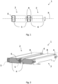
- Fig.1 shows a schematic front view of a coupling system 1 according to an embodiment.
- the coupling system 1 is designed for the mechanical synchronization of transport devices 2 arranged next to one another.
- the coupling system is provided for or in a vending machine 3.
- the coupling system 1 comprises two transport devices 2 arranged next to one another, each with a rotatable roller 4, and two coupling devices 5.
- the two rotatable rollers 4 extend along a common axis of rotation X.
- the rotatable rollers 4 each have a form-locking element 6 in an end region.
- the form-locking element 6 protrudes in a radial direction from the outer surface of the rotatable roller 4.
- the form-locking element 6 is preferably shaped like a pin, but this does not necessarily exclude other shapes.
- the end region of the rotatable roller 4 can, for example, have a stepped outer diameter, in particular a reduced outer diameter, than a central region of the rotatable roller 4.
- the coupling device 5 shown in the middle illustrates the position of the coupling device 5 in a predetermined end position in which the two rotatable rollers 4 are detachably connected to one another in a form-fitting manner.
- the coupling device 5 encloses, for example, the end regions of the two adjacent rotatable rollers 4 facing one another as well as the respective form-fitting element 6.
- the coupling device 5 shown on the left only encloses the end region of a rotatable roller 4, whereby in this case too the form-locking element 6 can engage in the coupling device 5.
- the coupling system shown as an example can be Fig.1 can be motor-driven either via the coupling device 5 shown on the left, the coupling device 5 shown in the middle or one of the two rotating rollers 4. Regardless of the drive side selected, the two coupling devices 5 and the two rotating rollers 4 are always driven simultaneously because they are mechanically synchronized.
- the middle coupling device 5 can be driven by a motor drive (not shown).
- the middle coupling device 5 drives the two rotatable rollers 4 simultaneously due to the positive connection.
- the rotatable roller 4 driven by the middle coupling device 5 drives the left coupling device 5, which is also positively connected to it.
- Fig.2 shows an isometric perspective view of a coupling system 1 according to a further embodiment with two coupled, adjacent transport devices 2.
- the coupling system 1 of the Fig.2 illustrated further embodiment essentially corresponds to the coupling system according to Fig.1 .
- the coupling system 1 differs, however, in that here the transport devices 2 each have two rotatable rollers 4 and a conveyor belt 8, which is stretched around the two rotatable rollers 4, for example, whereby these two rotatable rollers 4 of the individual transport device 2 naturally do not contain a common axis of rotation X, but are arranged parallel to one another.
- these two rotatable rollers 4 are referred to as the front rotatable roller and the rear rotatable roller.
- sectional view clearly illustrates that the releasable positive connection between the coupling device 5 and the rotatable roller 4 or the positive locking element 6 is present both in the circumferential direction for transmitting a drive torque and axially along the rotation axis X to secure against axial slipping.
- the front rotatable rollers 4 are connected to one another by the coupling device 5.
- the rear rotatable rollers 4 can be connected to one another.
- the rotational movement is transmitted to the rotatable roller 4 by means of a form-locking element 6 and this in turn sets the conveyor belt 8 in motion and the goods located on the conveyor belt 8 can be conveyed in the direction of an output.
- Fig.3 shows a schematic representation of a coupling device 5 according to an embodiment in various side views.
- a front side, a first end face 13A and a second end face 13B of the coupling device 5 or its base body 13 are shown.
- the coupling device 5 of the Fig.3 corresponds functionally essentially to the coupling device according to Fig.1 .
- the coupling device 5 differs, for example, in that a circumferential surface of the base body 13 has a plurality of teeth 15.
- the plurality of teeth 15 can, for example, be coupled to a gear drive or another drive for transmitting the drive torque, wherein the other drive is in engagement with the plurality of teeth 15 by means of a gear transmission.
- the gear drive can also have a transmission.
- the base body 13 contains a through hole 14.
- the through hole 14 extends here, for example, along the rotation axis X from the first end face 13A to the second end face 13B.
- a diameter of the through hole 14 corresponds essentially to the outer diameter of the end region of the rotatable roller 4 on which the coupling device 5 can be mounted.
- the base body 13 contains a first recess 7A and a second recess 7B.
- the first and second recess 7A, 7B are each designed to accommodate a first or second form-locking element 6 of the first or second rotatable roller 4 on the first or second end face 13A, 13B, i.e. to engage them.
- the form-locking element can contain two protruding sections which are arranged on opposite sides of the lateral surface. Consequently, the first or second recess 7A, 7B here also contains two sections, for example, in order to be able to accommodate the two sections of the form-locking element 6.
- first recess 7A and the second recess 7B are mirror-inverted. This means that while the first recess 7A extends counterclockwise from a reference position in the circumferential direction, the second recess 7B extends clockwise from the reference position in the circumferential direction.
- a nose 9 can thus be formed within the first and second recess or between the first and second recess 7A, 7B in the base body 13.
- the nose 9 can be an undercut which axially secures the coupling device 5 when the form-fitting element 6 rests against the nose 9.
- the embodiment in Fig.3 one nose 9 in each section of the first or second recess 7A, 7B.
- a section of the first or second recess 7A, 7B can also have a second nose 9.
- the undercut can be provided when the coupling device 5 is rotated both clockwise and counterclockwise.
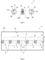
- Fig.4 shows a schematic front view of a vending machine 3 according to one embodiment with a coupling system 1 according to another embodiment.
- the vending machine 3 comprises a housing 10, an interior 11 and the coupling system 1.
- the coupling system 1 is an embodiment according to Fig. 1, Fig. 2 , Fig.3 or combinations thereof.
- the vending machine 3 may further include a front door, which is typically hinged to the housing 10.
- the front door and the housing 10 together form the interior 11 to accommodate the goods 12 to be sold, the control and cooling functions of the vending machine 3 and other vending machine functions.
- the front door may have a transparent glass or clear plastic panel which, when the front door is closed, provides a clear view into the interior 11 of the vending machine 3 and thus of the goods 12 housed therein, which are kept in an orderly manner in product compartments in the interior 11 of the vending machine 3.
- a suitable control panel may be provided which includes product selection input devices and money and credit processing devices which are generally known, as is a coin return device.
- the vending machine 3 may further include an optical and/or acoustic signaling device.
- a locking unit can be provided which enables the front door to be opened and closed in a safe manner for the purposes of maintenance, filling of the vending machine 3 and the like.
- the vending machine 3 can also contain a goods dispensing opening from which a sold goods product 12 can be removed by a buyer.
- the vending machine 3 has, for example, a plurality of goods compartments arranged in an array in the interior 11.
- Fig.4 the arrangement of three product compartments in the interior 11 of the vending machine 3 is shown as an example.
- the three product compartments are arranged in the same conveyor level by way of example, but other product compartments of the plurality of product compartments can also be arranged in other conveyor levels, i.e. below or above.
- five transport devices 2 are shown as an example, with the three left-hand transport devices 2 representing a coupling system 1. To the right of these, two further transport devices 2' are provided, which are configured for individual operation independently of the coupling system 1.
- the two transport devices 2 ⁇ are essentially identical to the transport devices 2 of the coupling system 1 and can be part of the coupling system 1 if required if the coupling device 5 is detachably connected in a form-fitting manner to the rotatable roller 4 of the adjacent transport device 2. In this way, the width of the goods compartments can be variably adjusted, wherein the coupling system 1 or each individual transport device 2' is assigned to a goods compartment and conveys the goods 12 stored therein.
- all of the transport devices 2, 2' provided are essentially identical.
- five, four, three, two or one goods compartments can thus be formed.
- the five transport devices 2' can be driven independently of one another, i.e. not coupled.
- two transport devices 2 of a coupling system 1 can be connected to one another. be coupled and assigned to a goods compartment.
- the five transport devices 2 can also optionally be coupled to form a coupling system 1.
- the individual goods compartments can each have a different size, although this is not absolutely necessary.
- the goods compartments can be variably adjustable in their width and height.
- the transport device 2, 2' is connected to a conveyor belt 8, as in Fig.2 shown, the upper horizontal region of the conveyor belt 8 forms the bottom surface of the goods compartment.
- Fig.5 shows a flow chart of a method V for configuring a coupling system 1.
- the method V for configuring the coupling system 1 comprises, for example, the steps of individually driving V1 a transport device 2 ⁇ , rotating V2 a coupling device 5, axially displacing V3 the coupling device 5, rotating V4 the coupling device 5 and jointly driving V5 the plurality of coupled transport devices 2.
- it is a method for configuring the coupling system 1 for or in a vending machine 3.
- Steps V1-V4 are illustrated graphically as examples and serve to illustrate the respective process step.
- the individual drive V1 includes a detachable positive connection between the coupling device 5 and the first rotatable roller 4A.
- the first positive locking element 6A of the first rotatable roller 4A can, for example, be in the second recess 7B of the coupling device 5.
- the coupling device 5 is thus not connected to the second rotatable roller 4B and only drives the first rotatable roller 4A.
- the nose 9 prevents in particular the coupling device 5 from slipping axially in the direction of the adjacent second rotatable roller 4B.
- the predetermined end position is present in which the coupling device 5 establishes the releasable positive connection to the first rotatable roller 4A for transmitting a drive torque.
- the coupling device 5 When the coupling device 5 is rotated V2 from the predetermined starting position, the coupling device 5 is rotated relative to the first rotatable roller 4A about the common axis of rotation X. In the process, the releasable positive connection along the common axis of rotation X between the coupling device 5 and the first rotatable roller 4A is released. This means that the coupling device 5 is rotated in relation to the first rotatable roller 4A until the first positive locking element 6A is no longer restricted in its axial degree of freedom by the nose. Consequently, the coupling device 5 can be displaced axially in relation to the first rotatable roller 4A after the rotation V2.
- the coupling device 5 is guided to the adjacent second rotatable roller 4B.
- the first form-locking element 6A can, for example, change from the second recess 7B to the first recess 7A, with the first and second recesses 7A, 7B merging into one another.
- the coupling device 5 is axially displaced V3 in such a way that the Coupling device 5 surrounds an end region of the adjacent first and second rotatable rollers 4A, 4B.
- the first form-locking element 6A is guided into engagement with the first recess 7A and the second form-locking element 6B is guided into engagement with the second recess 7B.
- the second rotatable roller 4B or the second form-locking element 6B is also connected in a form-locking manner in the circumferential direction by the coupling device 5.
- the form-locking elements 6A, 6B of the adjacent rotatable rollers 4A, 4B can be aligned with one another during axial displacement V3, for example.
- a subsequent step includes the rotation V4 of the coupling device 5 relative to the two adjacent rotatable rollers 4, i.e. the first and second rotatable rollers 4A, 4B, about the common axis of rotation X into the predetermined end position.
- the predetermined end position here is comparable to the end position described above in relation to step V1, wherein the coupling device 5 here establishes the releasable positive connection to the first rotatable roller 4A and to the second rotatable roller 4B for transmitting the drive torque.
- the nose 9 is thus displaced between the positive locking elements 6A, 6B and in particular prevents the coupling device 5 from slipping axially.
- the second rotatable roller 4B can be aligned relative to the first rotatable roller 4A and relative to the coupling device 5 such that the second positive locking element 6B engages in the coupling device 5 depending on a predetermined transmission direction of the drive torque such that a substantially play-free starting process of the coupling system 1 is provided.
- the joint driving V5 of the coupled transport devices 2 includes, for example, the transmission of the drive torque by means of a motor drive.
- only one coupling device 5 can be driven or several coupling devices 5. Since all rotatable rollers 4 of the coupling system 1 are mechanically synchronized, all transport devices 2 of the coupling system 1 are moved at the same conveying speed.
- the method V can be applied both forwards and backwards to couple or uncouple the rotatable rollers 4.
- the method V can also be applied only partially in the reverse order.
Landscapes
- Physics & Mathematics (AREA)
- General Physics & Mathematics (AREA)
- Vending Machines For Individual Products (AREA)
Applications Claiming Priority (1)
| Application Number | Priority Date | Filing Date | Title |
|---|---|---|---|
| DE102023101460.9A DE102023101460B3 (de) | 2023-01-20 | 2023-01-20 | Kopplungssystem sowie Kopplungsvorrichtung zur mechanischen Synchronisierung nebeneinander angeordneter Transportvorrichtungen sowie Verkaufsautomat und Verfahren zum Konfigurieren eines Kopplungssystems |
Publications (1)
| Publication Number | Publication Date |
|---|---|
| EP4403499A1 true EP4403499A1 (fr) | 2024-07-24 |
Family
ID=88511520
Family Applications (1)
| Application Number | Title | Priority Date | Filing Date |
|---|---|---|---|
| EP23205814.9A Pending EP4403499A1 (fr) | 2023-01-20 | 2023-10-25 | Système de couplage ainsi que dispositif de couplage pour la synchronisation mécanique de dispositifs de transport disposés côte à côte ainsi que distributeur automatique et procédé de configuration d'un système de couplage |
Country Status (2)
| Country | Link |
|---|---|
| EP (1) | EP4403499A1 (fr) |
| DE (1) | DE102023101460B3 (fr) |
Citations (10)
| Publication number | Priority date | Publication date | Assignee | Title |
|---|---|---|---|---|
| GB1082150A (en) | 1963-12-07 | 1967-09-06 | Acker Norbert Karl | Conveyor of multi-selection vending machines |
| SE416935B (sv) * | 1975-04-30 | 1981-02-16 | Interroll Foerdertechnik Gmbh | Frankopplingsbar drivrulle for rulltransportorer |
| JP2000082174A (ja) * | 1998-09-07 | 2000-03-21 | Sanwa Techno Kk | 自動販売機の商品搬送装置 |
| JP2004164214A (ja) * | 2002-11-12 | 2004-06-10 | Sanden Corp | 自動販売機の商品搬送装置及び自動販売機 |
| US6935486B2 (en) * | 2002-08-28 | 2005-08-30 | Production Automation, Inc. | Bushing system for live roller conveyor |
| CA2523393A1 (fr) * | 2005-10-14 | 2007-04-14 | Maytag Corporation | Systeme de transport de produits de distributeur automatique |
| WO2012107943A1 (fr) | 2011-02-08 | 2012-08-16 | Officine Meccaniche F.Lli Manea S.R.L. | Dispositif d'alimentation pour produits à l'intérieur de distributeurs automatiques |
| US20140116853A1 (en) * | 2012-10-25 | 2014-05-01 | Eric Medin Chinnock | Active control roller top modular conveying assembly |
| EP2568451B1 (fr) * | 2011-09-12 | 2014-05-07 | Astore, SIA | Moyen pour transporter des articles depuis une étagère d'un magasin automatique ou d'un distributeur vers un chariot et/ou du chariot vers l'étagère |
| CN209543473U (zh) * | 2019-05-17 | 2019-10-25 | 上海奢励实业有限公司 | 一种自动售卖机的储物机构 |
Family Cites Families (6)
| Publication number | Priority date | Publication date | Assignee | Title |
|---|---|---|---|---|
| DE1983545U (de) | 1968-01-15 | 1968-04-18 | Albert Schnellpressen | Kupplung am antrieb des formzylinders von rotationsdruckmaschinen. |
| FR2673691A1 (fr) | 1991-03-05 | 1992-09-11 | Europ Agence Spatiale | Dispositif d'accouplement mecanique separable. |
| FR2723155B1 (fr) | 1994-07-26 | 1996-10-11 | Nacam | Dispositif d'accouplement de deux arbres |
| JP2001134828A (ja) | 1999-11-02 | 2001-05-18 | Matsushita Refrig Co Ltd | 自動販売機 |
| ITVI20130214A1 (it) | 2013-08-09 | 2015-02-10 | Idea Srl | Magazzino automatico |
| DE102016107997A1 (de) | 2016-04-29 | 2017-11-02 | Weber Maschinenbau Gmbh Breidenbach | Fördereinheit |
-
2023
- 2023-01-20 DE DE102023101460.9A patent/DE102023101460B3/de active Active
- 2023-10-25 EP EP23205814.9A patent/EP4403499A1/fr active Pending
Patent Citations (10)
| Publication number | Priority date | Publication date | Assignee | Title |
|---|---|---|---|---|
| GB1082150A (en) | 1963-12-07 | 1967-09-06 | Acker Norbert Karl | Conveyor of multi-selection vending machines |
| SE416935B (sv) * | 1975-04-30 | 1981-02-16 | Interroll Foerdertechnik Gmbh | Frankopplingsbar drivrulle for rulltransportorer |
| JP2000082174A (ja) * | 1998-09-07 | 2000-03-21 | Sanwa Techno Kk | 自動販売機の商品搬送装置 |
| US6935486B2 (en) * | 2002-08-28 | 2005-08-30 | Production Automation, Inc. | Bushing system for live roller conveyor |
| JP2004164214A (ja) * | 2002-11-12 | 2004-06-10 | Sanden Corp | 自動販売機の商品搬送装置及び自動販売機 |
| CA2523393A1 (fr) * | 2005-10-14 | 2007-04-14 | Maytag Corporation | Systeme de transport de produits de distributeur automatique |
| WO2012107943A1 (fr) | 2011-02-08 | 2012-08-16 | Officine Meccaniche F.Lli Manea S.R.L. | Dispositif d'alimentation pour produits à l'intérieur de distributeurs automatiques |
| EP2568451B1 (fr) * | 2011-09-12 | 2014-05-07 | Astore, SIA | Moyen pour transporter des articles depuis une étagère d'un magasin automatique ou d'un distributeur vers un chariot et/ou du chariot vers l'étagère |
| US20140116853A1 (en) * | 2012-10-25 | 2014-05-01 | Eric Medin Chinnock | Active control roller top modular conveying assembly |
| CN209543473U (zh) * | 2019-05-17 | 2019-10-25 | 上海奢励实业有限公司 | 一种自动售卖机的储物机构 |
Also Published As
| Publication number | Publication date |
|---|---|
| DE102023101460B3 (de) | 2024-07-18 |
Similar Documents
| Publication | Publication Date | Title |
|---|---|---|
| DE19854629B4 (de) | Automatisiertes Lager | |
| DE2258064C3 (de) | Streifenschneidmaschine | |
| DE102008000921B4 (de) | Strecke mit linearem Kannendurchschub | |
| EP3150521B1 (fr) | Dispositif de groupement d'articles et procede de changement de format d'un tel dispositif | |
| EP2783819A2 (fr) | Trancheur haute puissance doté d'au moins une cassette de bande amovible | |
| CH418956A (de) | Maschine zum Kartonieren von Füllgut aller Art | |
| DE10301178B4 (de) | Vorrichtung zum Ausrichten und Verteilen | |
| EP0345585B1 (fr) | Dispositif de transport pour des bonbons | |
| DE19643163A1 (de) | Werkzeugwechselvorrichtung für eine Umformpresse sowie Umformpressen-Werkzeugwechselvorrichtungs-Anordnung | |
| WO2016109862A1 (fr) | Dispositif d'alimentation pour presse plieuse | |
| EP0089543A1 (fr) | Machine de remplissage et d'emballage de produits alimentaires | |
| DE69608081T2 (de) | Vorrichtung zur Extrusion von Plastomeren, Elastomeren und ähnlichen Materialien mit konvergierenden Schnecken | |
| EP3016760B1 (fr) | Dispositif et procédé pour transférer un élément et système d'outil | |
| EP1445224B2 (fr) | Dispositif pour former des piles d'articles plats | |
| DD150182A5 (de) | Maschine zum einwickeln und gruppieren von produkten | |
| EP2964550B1 (fr) | Dispositif de positionnement et/ou d'orientation d'un ou plusieurs composants déflecteurs réglables servant à diriger et/ou guider des articles dans un système de transport | |
| DE69617485T2 (de) | Mehrstufige Umformmaschine | |
| DE69227842T2 (de) | Vorrichtung zum Querschneiden von Holzfurnier | |
| DE102023101460B3 (de) | Kopplungssystem sowie Kopplungsvorrichtung zur mechanischen Synchronisierung nebeneinander angeordneter Transportvorrichtungen sowie Verkaufsautomat und Verfahren zum Konfigurieren eines Kopplungssystems | |
| WO2014071431A1 (fr) | Installation de production d'un ensemble constitué de plusieurs éléments | |
| DE102016113376A1 (de) | Transportvorrichtung | |
| DE60319892T2 (de) | Artikelpositioniermaschine | |
| DE3245260A1 (de) | Doppelnocken-teilgetriebe | |
| WO2003022057A2 (fr) | Diviseuse pour pate | |
| EP3225354A1 (fr) | Unité de manutention et système de changement de palettes |
Legal Events
| Date | Code | Title | Description |
|---|---|---|---|
| PUAI | Public reference made under article 153(3) epc to a published international application that has entered the european phase |
Free format text: ORIGINAL CODE: 0009012 |
|
| STAA | Information on the status of an ep patent application or granted ep patent |
Free format text: STATUS: THE APPLICATION HAS BEEN PUBLISHED |
|
| AK | Designated contracting states |
Kind code of ref document: A1 Designated state(s): AL AT BE BG CH CY CZ DE DK EE ES FI FR GB GR HR HU IE IS IT LI LT LU LV MC ME MK MT NL NO PL PT RO RS SE SI SK SM TR |
|
| STAA | Information on the status of an ep patent application or granted ep patent |
Free format text: STATUS: REQUEST FOR EXAMINATION WAS MADE |
|
| 17P | Request for examination filed |
Effective date: 20241127 |
|
| RBV | Designated contracting states (corrected) |
Designated state(s): AL AT BE BG CH CY CZ DE DK EE ES FI FR GB GR HR HU IE IS IT LI LT LU LV MC ME MK MT NL NO PL PT RO RS SE SI SK SM TR |
|
| STAA | Information on the status of an ep patent application or granted ep patent |
Free format text: STATUS: EXAMINATION IS IN PROGRESS |
|
| RIC1 | Information provided on ipc code assigned before grant |
Ipc: G07F 11/00 20060101ALI20250325BHEP Ipc: B65G 39/04 20060101AFI20250325BHEP |
|
| 17Q | First examination report despatched |
Effective date: 20250409 |
|
| GRAP | Despatch of communication of intention to grant a patent |
Free format text: ORIGINAL CODE: EPIDOSNIGR1 |
|
| STAA | Information on the status of an ep patent application or granted ep patent |
Free format text: STATUS: GRANT OF PATENT IS INTENDED |
|
| INTG | Intention to grant announced |
Effective date: 20260306 |