EP4403708A1 - Verbessertes system und verfahren zur steuerung eines drehbaren oberrahmens einer arbeitsmaschine - Google Patents
Verbessertes system und verfahren zur steuerung eines drehbaren oberrahmens einer arbeitsmaschine Download PDFInfo
- Publication number
- EP4403708A1 EP4403708A1 EP24152253.1A EP24152253A EP4403708A1 EP 4403708 A1 EP4403708 A1 EP 4403708A1 EP 24152253 A EP24152253 A EP 24152253A EP 4403708 A1 EP4403708 A1 EP 4403708A1
- Authority
- EP
- European Patent Office
- Prior art keywords
- hydraulic
- upper frame
- control
- hydraulic motor
- work machine
- Prior art date
- Legal status (The legal status is an assumption and is not a legal conclusion. Google has not performed a legal analysis and makes no representation as to the accuracy of the status listed.)
- Granted
Links
Images


Classifications
-
- E—FIXED CONSTRUCTIONS
- E02—HYDRAULIC ENGINEERING; FOUNDATIONS; SOIL SHIFTING
- E02F—DREDGING; SOIL-SHIFTING
- E02F9/00—Component parts of dredgers or soil-shifting machines, not restricted to one of the kinds covered by groups E02F3/00 - E02F7/00
- E02F9/08—Superstructures; Supports for superstructures
- E02F9/10—Supports for movable superstructures mounted on travelling or walking gears or on other superstructures
- E02F9/12—Slewing or traversing gears
- E02F9/121—Turntables, i.e. structure rotatable about 360°
- E02F9/123—Drives or control devices specially adapted therefor
-
- E—FIXED CONSTRUCTIONS
- E02—HYDRAULIC ENGINEERING; FOUNDATIONS; SOIL SHIFTING
- E02F—DREDGING; SOIL-SHIFTING
- E02F9/00—Component parts of dredgers or soil-shifting machines, not restricted to one of the kinds covered by groups E02F3/00 - E02F7/00
- E02F9/08—Superstructures; Supports for superstructures
- E02F9/10—Supports for movable superstructures mounted on travelling or walking gears or on other superstructures
- E02F9/12—Slewing or traversing gears
- E02F9/121—Turntables, i.e. structure rotatable about 360°
- E02F9/128—Braking systems
-
- E—FIXED CONSTRUCTIONS
- E02—HYDRAULIC ENGINEERING; FOUNDATIONS; SOIL SHIFTING
- E02F—DREDGING; SOIL-SHIFTING
- E02F9/00—Component parts of dredgers or soil-shifting machines, not restricted to one of the kinds covered by groups E02F3/00 - E02F7/00
- E02F9/20—Drives; Control devices
- E02F9/22—Hydraulic or pneumatic drives
- E02F9/2221—Control of flow rate; Load sensing arrangements
-
- E—FIXED CONSTRUCTIONS
- E02—HYDRAULIC ENGINEERING; FOUNDATIONS; SOIL SHIFTING
- E02F—DREDGING; SOIL-SHIFTING
- E02F9/00—Component parts of dredgers or soil-shifting machines, not restricted to one of the kinds covered by groups E02F3/00 - E02F7/00
- E02F9/20—Drives; Control devices
- E02F9/22—Hydraulic or pneumatic drives
- E02F9/2278—Hydraulic circuits
- E02F9/2285—Pilot-operated systems
-
- E—FIXED CONSTRUCTIONS
- E02—HYDRAULIC ENGINEERING; FOUNDATIONS; SOIL SHIFTING
- E02F—DREDGING; SOIL-SHIFTING
- E02F9/00—Component parts of dredgers or soil-shifting machines, not restricted to one of the kinds covered by groups E02F3/00 - E02F7/00
- E02F9/20—Drives; Control devices
- E02F9/22—Hydraulic or pneumatic drives
- E02F9/2278—Hydraulic circuits
- E02F9/2296—Systems with a variable displacement pump
-
- E—FIXED CONSTRUCTIONS
- E02—HYDRAULIC ENGINEERING; FOUNDATIONS; SOIL SHIFTING
- E02F—DREDGING; SOIL-SHIFTING
- E02F9/00—Component parts of dredgers or soil-shifting machines, not restricted to one of the kinds covered by groups E02F3/00 - E02F7/00
- E02F9/24—Safety devices, e.g. for preventing overload
Definitions
- the present invention relates to a system and to a method for controlling a rotatable upper frame of a work machine.
- the present invention relates to a system and to a method for controlling the rotation of a pivotable upper frame of a work machine, in particular an earth-moving machine such as an excavator, a digger or the like.
- an earth-moving machine such as an excavator, a digger or the like.
- a lower frame which carries the wheels or tracks that allow motion of the work machine with respect to the ground
- a pivotable upper frame which is carried by the lower frame in a rotatable manner about a vertical rotation axis, and in turn carries an operator's cab and a hydraulically actuated arm
- a hydrostatic transmission which is operatively interposed between the lower frame and the upper frame, and is configured to drive the upper frame in rotation with respect to the lower frame.
- Such work machines are usually provided with a brake assembly adapted to prevent the rotation of this latter.
- Such safety threshold is determined according to the aforementioned EN 474-5 regulation and depends, among other things, on the brake assembly configuration and on the moment of inertia of the work machine.
- the moment of inertia of the work machine may vary depending on the bucket and/or equipment temporarily attached on the arm of the work machine.
- the maximum pivoting speed of the upper frame may exceeds the safety threshold set out by EN 474-5 regulation, in particular when very heavy buckets and/or equipment are attached to the hydraulically actuated arm.
- An aim of the present invention is to satisfy the above-mentioned needs in an optimized and cost effective manner.
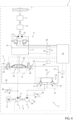
- number 1 denotes as a whole a work machine or vehicle or machinery, such as an earth-moving machine like an excavator, a digger or the like.
- work machine 1 comprises: a lower frame (not illustrated) or undercarriage, which carries the ground-engaging wheels or tracks that allow motion of work machine 1 with respect to the ground; and an upper frame 2 or superstructure, which is carried in a rotatable manner by lower frame preferably about a rotation axis orthogonal to the advancing plane of work machine 1 and, in turn, carries a hydraulically actuated arm and preferably also an operator's cab.
- work machine 1 comprises also a control system 3, which is configured to control the rotation of upper frame 2 with respect to the lower frame about said rotation axis.
- control system 3 preferably comprises a hydrostatic transmission 4, which is preferably carried by the upper frame, and is adapted to drive upper frame 2 in rotation about said rotation axis with respect to the lower frame.
- hydrostatic transmission 4 is preferably an open-circuit hydrostatic transmission.
- brake assembly which is adapted to prevent the rotation of upper frame 2.
- brake assembly is preferably configured to be operated when upper frame 2 is still, so as to hold this latter in a stationary condition.
- hydraulic transmission 4 preferably comprises a hydraulic pump 6, which is adapted to suck fluid from a tank 7 carried by work machine 1 and to provide at outlet a pressurized flow of hydraulic fluid.
- hydraulic pump 6 is carried by an engine 8 of work machine 1, such as an internal combustion engine, in order to be driven into rotation.
- work machine 1 such as an internal combustion engine
- hydraulic pump 6 is preferably a variable displacement pump, in particular a high-pressure variable displacement pump.
- hydrostatic transmission 4 comprises also a hydraulic motor 10, which is fluidly connected to hydraulic pump 6 and is adapted to be driven in rotation by the pressurized hydraulic fluid provided at outlet by hydraulic pump 6, in order to drive upper frame 2 in rotation about said rotation axis.
- hydraulic motor 10 is preferably mechanically connected to a slewing ring 11 carried by upper frame 2 by means of a gearbox assembly 12, in a manner per se known and therefore not further described.
- hydraulic motor 10 is a bidirectional or reversible hydraulic motor, in particular a fixed-displacement bidirectional hydraulic motor.
- control system 3 comprises: a control stage 14, which is operatively interposed between the hydraulic pump 6 and hydraulic motor 10 and is configured to control/regulate the flow of pressurized fluid fed from hydraulic pump 6 towards hydraulic motor 10, in order to control the rotation direction and/or the angular velocity of the same hydraulic motor 10; and a pilot stage 16, which is operatively connected to control stage 14 and is configured to control the operation of control stage 14 according to control signals imparted by an operator of work machine 1.
- control stage 14 is preferably fluidly connected to hydraulic motor 10 by means of a pair of hydraulic feed lines 15 and 17, each of which is connected to a correspondent inlet of hydraulic motor 10.
- control stage 14 controls control stage 14 to feed the pressurized hydraulic fluid along hydraulic line 15 or along hydraulic line 17, it is possible to control the rotation direction of hydraulic motor 10.
- Control stage 14 is preferably hydraulically operated and preferably comprises valve means 18, in particular hydraulically actuated valve means 18, which are operatively interposed between hydraulic pump 6 and hydraulic motor 10, and are configured to control/regulate the flow of pressurized fluid fed towards hydraulic motor 10 from hydraulic pump 6.
- valve means 18 may comprise a four-way three-position hydraulically actuated proportional valve 20.
- valve 20 is configured to prevent the pressurized fluid provided at outlet by hydraulic pump 6 to flow towards hydraulic motor 10 and to put the outlet of hydraulic pump 6 in fluid communication with tank 7.
- valve 20 is configured to put the outlet of hydraulic pump 6 in fluid communication with a first or with a second inlet of hydraulic motor 10 respectively via hydraulic line 15 or 17, in order to drive the same hydraulic motor 10 in rotation alternatively in a first direction or in a second direction, opposite to the first one.
- valve 20 is configured to put the outlet of hydraulic pump 6 in fluid communication with hydraulic line 15 and with said first inlet of hydraulic motor 10.
- valve 20 is configured to put the outlet of hydraulic pump 6 in fluid communication with hydraulic line 17 and with said second inlet of hydraulic motor 10.
- valve 20 is configured to be biased towards the first neutral position at rest.
- valve 20 may be actuated/displaced in said second or third operative position by pilot stage 16, in particular, by the hydraulic pressure applied by pilot stage 16 on valve 20.
- control system 3 preferably comprises a source of fluid 22, which is adapted to feed a flow of pressurized hydraulic fluid towards pilot stage 16.
- source of fluid 22 preferably comprises a second hydraulic pump 24 carried by engine 8, in particular a fixed displacement low-pressure hydraulic pump.
- Pilot stage 16 is preferably interposed between source of fluid 22 and control stage 14.
- pilot stage 16 is preferably fluidly connected to control stage 14 by means of a first pilot line 26 and a second pilot line 27 and is preferably configured to provide at output a hydraulic pilot signal to control the actuation of control stage 14.
- hydraulic pilot lines 26 and 27 are preferably connected to valve means 18 and are adapted to exert/apply a hydraulic pressure on the same valve means 18 in order to actuate it.
- hydraulic pilot lines 26 and 27 are preferably connected to valve 20 and are adapted to exert a hydraulic pressure on the same valve 20 in order to arrange/ displace the same valve 20 towards said first operative position or towards said second operative position respectively.
- pilot stage 16 preferably comprises valve means 30, which are adapted to divert/route the flow of pressurized hydraulic fluid provided at outlet by source 22 towards first pilot line 26 or towards second pilot line 27, in order to provide a hydraulic pilot signal adapted to actuate valve means 18.
- Valve means 30 preferably comprises a pair of hydraulic valves 31 and 32, which are adapted to be operated to put hydraulic pilot 26 or hydraulic pilot line 27 in fluid communication with source 22, in order to arrange/displace valve 20 toward said first or second operative position.
- valves 31 and 32 may comprise proportional three-way two-position hydraulic valves.
- control system 3 preferably comprises an input device 34, such as a lever or a joystick, which may be carried within the operator's cab and is configured to be handled by a work machine 1 operator in order to impart control signals for controlling the operation of pilot stage 16.
- input device 34 such as a lever or a joystick
- input device 34 is operatively connected to valve means 30 and is adapted to be operated by work machine operator to actuate the same valve means 30 in order to pressurize hydraulic pilot line 26 or hydraulic pilot line 27 and actuate control stage 14 accordingly.
- control system 3 may further comprise a limiting-pressure or relief valve 38, which is operatively interposed between hydraulic pump 6 and control stage 14, and is configured to limit the maximum pressure of the hydraulic fluid provided at outlet by hydraulic pump 6 and fed towards control stage 14.
- a limiting-pressure or relief valve 38 which is operatively interposed between hydraulic pump 6 and control stage 14, and is configured to limit the maximum pressure of the hydraulic fluid provided at outlet by hydraulic pump 6 and fed towards control stage 14.
- control system 3 may further comprise a further limiting-pressure or relief valve 40, which is operatively interposed between source of fluid 22 and pilot stage 16, and is configured to limit the maximum pressure of the hydraulic fluid provided at outlet by source of fluid 22 and fed towards pilot stage 16.
- a further limiting-pressure or relief valve 40 which is operatively interposed between source of fluid 22 and pilot stage 16, and is configured to limit the maximum pressure of the hydraulic fluid provided at outlet by source of fluid 22 and fed towards pilot stage 16.
- hydrostatic transmission 4 may be also configured in order to be able to reduce, during operation, the rotation speed of upper frame 2, i.e. to brake upper frame 2.
- the braking operation of upper frame 2 provided by hydrostatic transmission is a passive braking operation.
- valve means 18 are preferably closed, meaning that valve 20 is in the first neutral position, and the pressurized hydraulic fluid fed towards hydraulic motor 10 is trapped between the same hydraulic motor 10 and valve means 18, within hydraulic feed line 15 and hydraulic feed line 17.
- hydrostatic transmission 4 may be provided with a pair of limiting pressure or relief valves 13, which are operatively interposed between hydraulic pump 6 and hydraulic motor 10, along hydraulic feed line 15 and hydraulic feed line 17 respectively, and are configured to discharge/route to tank 7 the pressurized hydraulic fluid trapped within hydraulic feed lines 15 and 17 when the pressure of this latter exceeds a predetermined pressure threshold.
- Relief valves 13, in particular, are preferably configured to be normally closed and are adapted to be opened during braking operation of upper frame 2, so that the pressurized hydraulic fluid trapped within hydraulic feed lines 15 and 17 may be routed to tank 7.
- relief valve 13 are preferably configured to be normally closed, and to open when the pressure of the hydraulic fluid within hydraulic feed line 15 or hydraulic feed line 17 exceeds said predetermined threshold.
- relief valves 13 may limit the maximum pressure of the hydraulic fluid reached within hydraulic feed line 15 or hydraulic feed line 17 opposite to the rotation direction of hydraulic motor 10.
- control system 3 preferably comprises also electrically actuated valve means 42, which are operatively interposed between pilot stage 16 and control stage 14 and are configured to control/regulate/limit the pressure of the hydraulic fluid fed from pilot stage 16 towards control stage 14, in order to control the actuation of control stage 14 accordingly.
- electrically actuated valve means 42 preferably comprises a pair of solenoid-controlled proportional hydraulic valves 43 and 44, which are arranged respectively on hydraulic pilot line 26 and hydraulic pilot line 27 and are configured to regulate/limit the hydraulic pressure exerted by the same hydraulic pilot lines 26 and 27 on valve means 18.
- solenoid-controlled proportional valves 43 and 44 preferably are two-way two-position solenoid -controlled proportional valves.
- valves 43 and 44 are preferably arranged immediately upstream valve 20 on hydraulic pilot lines 26 and 27 respectively, and they are adapted to limit/regulate the pilot pressure exerted by the same hydraulic pilot lines 26 and 27 on valve 20, in order to control the actuation of control stage 14 accordingly.
- valves 43 and 44 are configured to be operated between an open position and a closed position.
- valves 43 and 44 put pilot stage 16 in fluid communication with control stage 14 respectively.
- valves 43 and 44 prevent fluid communication between pilot stage 16 and control stage 14 and route the hydraulic fluid fed by source 22 and pilot stage 16 to tank 7.
- valves 43 and 44 are preferably configured to be biased towards said open position at rest, and they may be actuated in said closed positions by their respective solenoid.
- control system 3 further comprises sensor means 50, which are configured to detect/measure the pressure of the hydraulic fluid fed from control stage 14 to hydraulic motor 10.
- sensor means 50 preferably comprises a pair of pressure sensors 51 and 52, which are configured to detect/measure the pressure of the hydraulic fluid within hydraulic feed lines 15 and 17 respectively.
- pressure sensors 51 and 52 are configured to detect the pressure of the pressurized hydraulic fluid fed towards hydraulic motor 10.
- sensor means may further comprise a pair of pressure sensors 54 and 55, which are respectively connected to hydraulic pilot line 26 and to hydraulic pilot line 27, downstream pilot stage 16, and are adapted to measure/determine the pressure of the hydraulic fluid within these latter.
- control system 3 further comprises an electronic control unit 56, which is operatively connected at least to sensor means 50, and comprises elaboration means configured to retrieve data from sensor means 50 related to the pressure of hydraulic fluid fed towards hydraulic motor 10 and to elaborate these latter to provide control signals adapted to control the rotational velocity of upper frame 2 according to the control logic that is described more in detail in the following.
- electronic control unit 56 is configured to determine/estimate the inertia of the upper frame 2 based on the data retrieved from sensor means 50.
- electronic control unit 56 is configured to determine/estimate the inertia of the upper frame 2 as function of the pressure of hydraulic fluid within hydraulic motor 10.
- electronic control unit 56 is preferably configured to determine/calculate the maximum allowable rotational velocity of upper frame 2 according to the EN 474-5 regulation, in particular the EN 474-5:2022 regulation.
- EN 474-5 regulation sets out a maximum allowable rotational velocity of upper frame 2, which depends at least on the configuration of the aforementioned brake assembly and on the inertia of upper frame 2 of work machine 1.
- electronic control unit 56 is preferably configured to determine/calculate, based on the estimated inertia of upper frame 2 and preferably also on said brake assembly configuration, the maximum allowable rotational velocity of upper frame 2 that meets the requirements of EN 474-5 regulation, in particular of EN 474-5:2022 regulation.
- electronic control unit 56 is preferably configured to determine/calculate, based on the estimated inertia of upper frame 2 and preferably also on said brake assembly configuration, the maximum allowable rotational velocity of upper frame 2 that allows to not exceed the maximum deceleration swing angle set out by EN 474-5 regulation during upper frame 2 deceleration.
- the maximum allowable rotational velocity set out by EN 474-5 regulation depends on the brake assembly 3 configuration and on the inertia of upper frame 2.
- electronic control unit 56 is preferably configured in order to limit/control the flowrate of the hydraulic fluid fed towards hydraulic motor 10, such that the rotational velocity of upper frame 2 about its rotation axis does not exceed said maximum allowable rotational velocity.
- electronic control unit 56 is preferably operatively connected to valve means 42 and is preferably configured to provide control signals to the same valve means 42 adapted to limit/regulate the hydraulic pilot pressure applied on control stage 14, in order to limit/control the flowrate of hydraulic fluid fed towards hydraulic motor 10 such that the rotational velocity of hydraulic motor 10 and accordingly of upper frame 2 does not exceed said maximum allowable rotational velocity.
- electronic control unit 56 is preferably configured to provide control signals to valve means 42 adapted to limit/regulate the hydraulic pilot pressure applied valve means 18, in order to limit/regulate the actuation of the same valve means 18 and control the rotational velocity of upper frame 2 accordingly.
- electronic control unit 56 may be operatively connected to hydraulic pump and may be configured to provide control signals to the same hydraulic pump 6 adapted to control its displacement, in order to limit/control the flowrate of hydraulic fluid fed towards hydraulic motor 10 such that the rotational velocity of hydraulic motor 10 and accordingly of upper frame 2 does not exceed said maximum allowable rotational velocity.
- electronic control unit 56 may be further configured to determine/calculate the rotational velocity of hydraulic motor 10 and of upper frame 2 based on the flowrate of hydraulic fluid fed towards the same hydraulic motor 10, in a manner per se known and therefore not further described.
- Electronic control unit 56 may be further connected to pressure sensors 54 and 55, and may be configured to retrieve data related to the pressure of hydraulic fluid within hydraulic pilot line 26 and within hydraulic pilot line 27, in order to determine the direction of actuation of input device 34.
- control system 3 The operation of the above-described control system 3 is the following.
- work machine 1 operator handles input device 34 to actuate pilot stage 16, meaning to actuate valve assembly 30.
- pilot stage 16 hydraulic pilot pressure within hydraulic pilot line 26 or within hydraulic pilot line 27 increases and control stage 14 is actuated accordingly.
- a flow of pressurized hydraulic fluid is fed towards hydraulic motor 10 via hydraulic feed line 15 or via hydraulic feed line 17, in order to drive the same hydraulic engine 10 in rotation.
- electronic control 56 unit retrieves from sensor means 50 data related to the pressure of the hydraulic fluid fed towards hydraulic motor 10.
- electronic control unit 56 calculates the inertia of upper frame 2 and the maximum allowable rotational velocity of upper frame 2 to meet the requirements of EN 474-5 regulations.
- electronic control unit 56 limits/regulates the flowrate of the hydraulic fluid fed towards hydraulic motor 10 such that the rotational velocity of upper frame does not exceed said maximum allowable rotational velocity.
- electronic control unit 56 preferably actuates valve means 42 to limit/regulate the hydraulic pilot pressure applied on control stage 14 and limit/control the flowrate of hydraulic fluid fed towards hydraulic motor 10 accordingly.
- electronic control unit 56 controls the displacement of hydraulic pump 6 to limit/control the flowrate of hydraulic fluid it provides at outlet accordingly.
- the invention is furthermore directed to a method for controlling the pivotable upper frame 2 of the described work machine 1, which comprises at least the following steps:
- said step iii) preferably comprises the step of controlling/regulating the flowrate of the hydraulic fluid fed towards hydraulic motor 10 such that the rotational velocity of upper frame 2 does not exceed said maximum allowable rotational velocity.
- said step iii) preferably comprises the step of calculating/determining the maximum allowable rotational velocity of upper frame 2 that meets the requirement of EN 474-5 regulation, in particular 474-5:2022 regulation.
- said step iii) preferably comprises the step of calculating/determining, based on the estimated inertia of upper frame 2 and preferably also on said brake assembly configuration, the maximum allowable rotational velocity of upper frame 2 that allows to not exceed the maximum deceleration swing angle set out by EN 474-5 regulation during upper frame 2 deceleration.
- said step iv) preferably comprises the step of controlling valve means 42 in order to limit/regulate the hydraulic pilot pressure applied on control stage 14, and limit/control the flowrate of hydraulic fluid fed towards hydraulic motor 10 accordingly, such that the rotational velocity of hydraulic motor 10 and accordingly of upper frame 2 does not exceed said maximum allowable rotational velocity.
- said step iv) preferably comprises the step of controlling valve means 42 in order to limit/regulate the hydraulic pilot pressure applied valve means 18, to control the rotational velocity of upper frame 2 accordingly.
- said step iv) preferably comprises the step of controlling the displacement of hydraulic pump 6 in order to limit/control the flowrate of hydraulic fluid fed towards hydraulic motor 10, such that the rotational velocity of hydraulic motor 10 and accordingly of upper frame 2 does not exceed said maximum allowable rotational velocity.
- work machine 1 operator is not required to set manually the operative parameters of work machine 1 according to the bucket or equipment temporarily attached to the hydraulically operated arm, with all the benefits that this entail.
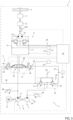
- control system 3 may be further provided with an angular velocity sensor 100, which is operatively coupled to upper frame 2 and is configured to detect/measure the angular velocity of this latter.
- Electronic control unit 56 may be operatively connected to angular velocity sensor 100 in order to be able to retrieve data related to the rotational velocity of upper frame 2 from this latter.
- electronic control unit 56 may be configured to determined, on the basis of the data provided by angular velocity sensor 100, the angular acceleration of upper frame 2.
- hydraulic motor 10 may be a variable displacement hydraulic motor, in particular a reversible or bidirectional variable displacement hydraulic motor.
- Electronic control unit 56 may be operatively connected to hydraulic motor 10 and may be configured to control its displacement in order to control rotation speed of hydraulic motor 10 and of upper frame 2 accordingly, in order to implement the control method above described.
- control system 3 may further comprise an acceleration sensor 110, which is operatively connected to upper frame 2 and is configured to detect/measure the angular acceleration of this latter.
- Electronic control unit 56 may be operatively connected to acceleration sensor 110 in order to be able to retrieve data related to the angular acceleration of upper frame 2 from this latter.
- control system 3 may be provided with two solenoid-controlled proportional limiting-pressure or relief valves 113, which are operatively interposed between hydraulic pump 6 and hydraulic motor 10, along hydraulic feed line 15 and hydraulic feed line 17, and are adapted to operate during upper frame 2 braking operation, as described with reference to relief valves 13.
- Electronic control unit 56 may be operatively connected to relief valves 113 and may be configured to control their operation during upper frame 2 braking operation, in order to control the rotational velocity of upper frame 2 so that it does not exceed said maximum allowable rotational velocity.
- electronic control unit 56 may be configured to set the threshold pressure of relief valves 113 involved in the braking operation, i.e. the relief valve 113 located on the hydraulic feed line 15 or 17 opposite to the rotation direction of hydraulic motor 10, so as to increase the maximum backpressure allowed within such hydraulic line and increase the braking torque provided by hydraulic motor 10 accordingly.
- the method according to the present invention may comprise the step of setting the threshold pressure of relief valves 113 in order to vary the maximum backpressure allowed within hydraulic feed line 15 or hydraulic feed line 17 and vary the braking torque provided by hydraulic motor 10 accordingly.
- control system 3 may be provided with a brake assembly 200, which is operatively interposed between hydraulic motor 10 and upper frame 2 and is configured to provide a braking torque adapted to reduce the rotational velocity of upper frame 2.
- brake assembly 200 may be carried by hydraulic motor 10, meaning that it may be arranged immediately upstream gearbox assembly 12.
- Electronic control unit 56 may be operatively connected to brake assembly 200 and may be configured to control its operation so that the braking angle does not exceed a maximum allowable value and/or so that the rotational velocity of upper frame 2 does not exceed said maximum allowable rotational velocity.
- the method of the present invention may comprise the step of controlling brake assembly 200 so that the rotational velocity of upper frame 2 does not exceed said maximum allowable rotational velocity
- the technical effect associated to the presence of solenoid-controlled proportional relief valves 113 and/or brake assembly 200 is related to the possibility of increasing the maximum allowable rotational velocity calculated according to EN 474-5 regulation and therefore to not limit the performances of the work machine 1, meaning without reducing the upper frame 2 maximum allowable rotational velocity, as said maximum allowable rotational velocity set out by EN474-5 regulation increases with the increased braking performances.
- pilot stage 16 may not comprise valve means 30 connected to input device 34.
- Input device 34 may be operatively connected to electronic control unit 56 in order to impart control signals adapted to control the actuation of valve means 42.
- electronic control unit 56 may be configured to control the actuation of valve means 42 according to the control signals provided by input device 34, in order to operate control stage 14 accordingly.
- input device 34 may be configured to provide electronic control signals to electronic control unit 56, and this latter may be configured to control solenoid-controlled proportional hydraulic valves 43 and 44 in order to operate control stage 14 according to the electronic control signals provided by work machine 1 driver via input device 34.
- input device 34 may comprise a joystick or a lever electrically connected to electronic control unit 56.
- electronic control unit 56 may be configured to actuate solenoid-controlled proportional hydraulic valve 43 or 44 in order to arrange valve 20 in said second or third operative position respectively, in order to fluidly connect the outlet of hydraulic pump 6 with the hydraulic feed line 15 or 17 opposite to the rotation direction of hydraulic motor 10.
- hydraulic pump 6 may feed a flow of pressurized hydraulic flow towards hydraulic motor 10 along the hydraulic feed line 15 or 17 opposite to the rotation direction of hydraulic motor 10, in order to rapidly increase the backpressure of this latter within the correspondent hydraulic fluid line 15 or 17 and the braking torque provided by hydraulic motor 10.
Landscapes
- Engineering & Computer Science (AREA)
- Mining & Mineral Resources (AREA)
- Civil Engineering (AREA)
- General Engineering & Computer Science (AREA)
- Structural Engineering (AREA)
- Physics & Mathematics (AREA)
- Fluid Mechanics (AREA)
- Fluid-Pressure Circuits (AREA)
Applications Claiming Priority (1)
| Application Number | Priority Date | Filing Date | Title |
|---|---|---|---|
| IT102023000000600A IT202300000600A1 (it) | 2023-01-17 | 2023-01-17 | Metodo e sistema migliorati per controllare un telaio superiore girevole di una macchina da lavoro |
Publications (2)
| Publication Number | Publication Date |
|---|---|
| EP4403708A1 true EP4403708A1 (de) | 2024-07-24 |
| EP4403708B1 EP4403708B1 (de) | 2025-10-01 |
Family
ID=86007314
Family Applications (1)
| Application Number | Title | Priority Date | Filing Date |
|---|---|---|---|
| EP24152253.1A Active EP4403708B1 (de) | 2023-01-17 | 2024-01-16 | Verbessertes system und verfahren zur steuerung eines drehbaren oberrahmens einer arbeitsmaschine |
Country Status (2)
| Country | Link |
|---|---|
| EP (1) | EP4403708B1 (de) |
| IT (1) | IT202300000600A1 (de) |
Citations (4)
| Publication number | Priority date | Publication date | Assignee | Title |
|---|---|---|---|---|
| JPH1136376A (ja) * | 1997-07-17 | 1999-02-09 | Komatsu Ltd | 作業機における旋回起動制御装置 |
| JPH1137108A (ja) * | 1997-07-24 | 1999-02-09 | Komatsu Ltd | 油圧作業機械の油圧制御装置 |
| CN102704523B (zh) * | 2011-03-25 | 2016-04-27 | 日立建机株式会社 | 混合动力式工程机械 |
| EP3249110B1 (de) * | 2014-12-24 | 2019-08-21 | Volvo Construction Equipment AB | Schwingsteuerungsvorrichtung einer baumaschine und steuerungsverfahren dafür |
Family Cites Families (1)
| Publication number | Priority date | Publication date | Assignee | Title |
|---|---|---|---|---|
| GB2625781B (en) * | 2022-12-23 | 2025-02-05 | Caterpillar Sarl | A method of operating a work vehicle according to a maximum allowable swing speed |
-
2023
- 2023-01-17 IT IT102023000000600A patent/IT202300000600A1/it unknown
-
2024
- 2024-01-16 EP EP24152253.1A patent/EP4403708B1/de active Active
Patent Citations (4)
| Publication number | Priority date | Publication date | Assignee | Title |
|---|---|---|---|---|
| JPH1136376A (ja) * | 1997-07-17 | 1999-02-09 | Komatsu Ltd | 作業機における旋回起動制御装置 |
| JPH1137108A (ja) * | 1997-07-24 | 1999-02-09 | Komatsu Ltd | 油圧作業機械の油圧制御装置 |
| CN102704523B (zh) * | 2011-03-25 | 2016-04-27 | 日立建机株式会社 | 混合动力式工程机械 |
| EP3249110B1 (de) * | 2014-12-24 | 2019-08-21 | Volvo Construction Equipment AB | Schwingsteuerungsvorrichtung einer baumaschine und steuerungsverfahren dafür |
Also Published As
| Publication number | Publication date |
|---|---|
| EP4403708B1 (de) | 2025-10-01 |
| IT202300000600A1 (it) | 2024-07-17 |
Similar Documents
| Publication | Publication Date | Title |
|---|---|---|
| EP2071196B1 (de) | Hydraulische antriebsvorrichtung und arbeitsmaschine | |
| US10378185B2 (en) | Work machine | |
| JP4111286B2 (ja) | 建設機械の走行制御方法及び同装置 | |
| EP1577447B1 (de) | Hydraulische Steuervorrichtung für Hydraulikbagger | |
| CN102066148B (zh) | 静液传动式压实机中多个推进泵的方法和布置 | |
| EP2466017A1 (de) | Hydraulischer Antrieb mit geschlossenem Kreis mit Unterstützung einer Pumpe aus einem offenen Kreis für Hochgeschwindigkeitsfahrbewegungen | |
| EP1988221B1 (de) | Drehtischdrehantriebsvorrichtung für eine baumaschine | |
| WO2009045285A1 (en) | Hydraulics management for bounded implements of construction machines | |
| JP6961643B2 (ja) | ホイール式作業車両 | |
| EP3421845A1 (de) | Nutzfahrzeug | |
| US20220049471A1 (en) | Working machine | |
| EP4403708B1 (de) | Verbessertes system und verfahren zur steuerung eines drehbaren oberrahmens einer arbeitsmaschine | |
| EP4381141B1 (de) | Steuerung eines hydraulischen systems einer baumaschine | |
| US7607245B2 (en) | Construction machine | |
| US11725364B2 (en) | Hydraulic system of working machine | |
| US6360538B1 (en) | Method and an apparatus for an electro-hydraulic system on a work machine | |
| CN111344459A (zh) | 工程机械的驱动系统 | |
| EP3652025B1 (de) | Kriechsystem für ein baufahrzeug | |
| JP7800180B2 (ja) | 油圧駆動装置及びこれを備えた建設機械 | |
| US20040249537A1 (en) | Machine tool and method for operating machine tool | |
| JPH07189914A (ja) | 可変容量型油圧ポンプの制御装置 | |
| JPH09324446A (ja) | 建設車両の油圧駆動装置 | |
| KR20180032510A (ko) | 정역학적 회전 구동 장치 및 정역학적 회전 구동 장치의 제어 방법 | |
| JP4425804B2 (ja) | ロータ式掘削作業車両及びロータ掘削制御方法 | |
| JP3681409B2 (ja) | 油圧ショベル |
Legal Events
| Date | Code | Title | Description |
|---|---|---|---|
| PUAI | Public reference made under article 153(3) epc to a published international application that has entered the european phase |
Free format text: ORIGINAL CODE: 0009012 |
|
| STAA | Information on the status of an ep patent application or granted ep patent |
Free format text: STATUS: THE APPLICATION HAS BEEN PUBLISHED |
|
| AK | Designated contracting states |
Kind code of ref document: A1 Designated state(s): AL AT BE BG CH CY CZ DE DK EE ES FI FR GB GR HR HU IE IS IT LI LT LU LV MC ME MK MT NL NO PL PT RO RS SE SI SK SM TR |
|
| STAA | Information on the status of an ep patent application or granted ep patent |
Free format text: STATUS: REQUEST FOR EXAMINATION WAS MADE |
|
| 17P | Request for examination filed |
Effective date: 20250124 |
|
| GRAP | Despatch of communication of intention to grant a patent |
Free format text: ORIGINAL CODE: EPIDOSNIGR1 |
|
| STAA | Information on the status of an ep patent application or granted ep patent |
Free format text: STATUS: GRANT OF PATENT IS INTENDED |
|
| INTG | Intention to grant announced |
Effective date: 20250527 |
|
| GRAS | Grant fee paid |
Free format text: ORIGINAL CODE: EPIDOSNIGR3 |
|
| GRAA | (expected) grant |
Free format text: ORIGINAL CODE: 0009210 |
|
| STAA | Information on the status of an ep patent application or granted ep patent |
Free format text: STATUS: THE PATENT HAS BEEN GRANTED |
|
| AK | Designated contracting states |
Kind code of ref document: B1 Designated state(s): AL AT BE BG CH CY CZ DE DK EE ES FI FR GB GR HR HU IE IS IT LI LT LU LV MC ME MK MT NL NO PL PT RO RS SE SI SK SM TR |
|
| REG | Reference to a national code |
Ref country code: GB Ref legal event code: FG4D Ref country code: CH Ref legal event code: F10 Free format text: ST27 STATUS EVENT CODE: U-0-0-F10-F00 (AS PROVIDED BY THE NATIONAL OFFICE) Effective date: 20251001 |
|
| REG | Reference to a national code |
Ref country code: IE Ref legal event code: FG4D |
|
| REG | Reference to a national code |
Ref country code: DE Ref legal event code: R096 Ref document number: 602024000757 Country of ref document: DE |
|
| REG | Reference to a national code |
Ref country code: NL Ref legal event code: MP Effective date: 20251001 |
|
| REG | Reference to a national code |
Ref country code: AT Ref legal event code: MK05 Ref document number: 1842622 Country of ref document: AT Kind code of ref document: T Effective date: 20251001 |
|
| PG25 | Lapsed in a contracting state [announced via postgrant information from national office to epo] |
Ref country code: NL Free format text: LAPSE BECAUSE OF FAILURE TO SUBMIT A TRANSLATION OF THE DESCRIPTION OR TO PAY THE FEE WITHIN THE PRESCRIBED TIME-LIMIT Effective date: 20251001 |
|
| PG25 | Lapsed in a contracting state [announced via postgrant information from national office to epo] |
Ref country code: ES Free format text: LAPSE BECAUSE OF FAILURE TO SUBMIT A TRANSLATION OF THE DESCRIPTION OR TO PAY THE FEE WITHIN THE PRESCRIBED TIME-LIMIT Effective date: 20251001 |
|
| REG | Reference to a national code |
Ref country code: LT Ref legal event code: MG9D |
|
| PG25 | Lapsed in a contracting state [announced via postgrant information from national office to epo] |
Ref country code: NO Free format text: LAPSE BECAUSE OF FAILURE TO SUBMIT A TRANSLATION OF THE DESCRIPTION OR TO PAY THE FEE WITHIN THE PRESCRIBED TIME-LIMIT Effective date: 20260101 |
|
| PGFP | Annual fee paid to national office [announced via postgrant information from national office to epo] |
Ref country code: DE Payment date: 20260127 Year of fee payment: 3 |
|
| PG25 | Lapsed in a contracting state [announced via postgrant information from national office to epo] |
Ref country code: FI Free format text: LAPSE BECAUSE OF FAILURE TO SUBMIT A TRANSLATION OF THE DESCRIPTION OR TO PAY THE FEE WITHIN THE PRESCRIBED TIME-LIMIT Effective date: 20251001 Ref country code: HR Free format text: LAPSE BECAUSE OF FAILURE TO SUBMIT A TRANSLATION OF THE DESCRIPTION OR TO PAY THE FEE WITHIN THE PRESCRIBED TIME-LIMIT Effective date: 20251001 Ref country code: AT Free format text: LAPSE BECAUSE OF FAILURE TO SUBMIT A TRANSLATION OF THE DESCRIPTION OR TO PAY THE FEE WITHIN THE PRESCRIBED TIME-LIMIT Effective date: 20251001 |
|
| PGFP | Annual fee paid to national office [announced via postgrant information from national office to epo] |
Ref country code: IT Payment date: 20260131 Year of fee payment: 3 |
|
| PG25 | Lapsed in a contracting state [announced via postgrant information from national office to epo] |
Ref country code: RS Free format text: LAPSE BECAUSE OF FAILURE TO SUBMIT A TRANSLATION OF THE DESCRIPTION OR TO PAY THE FEE WITHIN THE PRESCRIBED TIME-LIMIT Effective date: 20260101 |
|
| PG25 | Lapsed in a contracting state [announced via postgrant information from national office to epo] |
Ref country code: IS Free format text: LAPSE BECAUSE OF FAILURE TO SUBMIT A TRANSLATION OF THE DESCRIPTION OR TO PAY THE FEE WITHIN THE PRESCRIBED TIME-LIMIT Effective date: 20260201 |
|
| PGFP | Annual fee paid to national office [announced via postgrant information from national office to epo] |
Ref country code: FR Payment date: 20260126 Year of fee payment: 3 |
|
| PG25 | Lapsed in a contracting state [announced via postgrant information from national office to epo] |
Ref country code: CZ Free format text: LAPSE BECAUSE OF FAILURE TO SUBMIT A TRANSLATION OF THE DESCRIPTION OR TO PAY THE FEE WITHIN THE PRESCRIBED TIME-LIMIT Effective date: 20251001 Ref country code: PT Free format text: LAPSE BECAUSE OF FAILURE TO SUBMIT A TRANSLATION OF THE DESCRIPTION OR TO PAY THE FEE WITHIN THE PRESCRIBED TIME-LIMIT Effective date: 20260202 |
|
| PG25 | Lapsed in a contracting state [announced via postgrant information from national office to epo] |
Ref country code: PL Free format text: LAPSE BECAUSE OF FAILURE TO SUBMIT A TRANSLATION OF THE DESCRIPTION OR TO PAY THE FEE WITHIN THE PRESCRIBED TIME-LIMIT Effective date: 20251001 |
|
| PG25 | Lapsed in a contracting state [announced via postgrant information from national office to epo] |
Ref country code: LV Free format text: LAPSE BECAUSE OF FAILURE TO SUBMIT A TRANSLATION OF THE DESCRIPTION OR TO PAY THE FEE WITHIN THE PRESCRIBED TIME-LIMIT Effective date: 20251001 |