EP4403776A1 - Spiralverdichter und kühlvorrichtung - Google Patents
Spiralverdichter und kühlvorrichtung Download PDFInfo
- Publication number
- EP4403776A1 EP4403776A1 EP22886718.0A EP22886718A EP4403776A1 EP 4403776 A1 EP4403776 A1 EP 4403776A1 EP 22886718 A EP22886718 A EP 22886718A EP 4403776 A1 EP4403776 A1 EP 4403776A1
- Authority
- EP
- European Patent Office
- Prior art keywords
- circumferential wall
- scroll compressor
- valve seat
- valve body
- suction
- Prior art date
- Legal status (The legal status is an assumption and is not a legal conclusion. Google has not performed a legal analysis and makes no representation as to the accuracy of the status listed.)
- Granted
Links
Images


Classifications
-
- F—MECHANICAL ENGINEERING; LIGHTING; HEATING; WEAPONS; BLASTING
- F04—POSITIVE - DISPLACEMENT MACHINES FOR LIQUIDS; PUMPS FOR LIQUIDS OR ELASTIC FLUIDS
- F04C—ROTARY-PISTON, OR OSCILLATING-PISTON, POSITIVE-DISPLACEMENT MACHINES FOR LIQUIDS; ROTARY-PISTON, OR OSCILLATING-PISTON, POSITIVE-DISPLACEMENT PUMPS
- F04C18/00—Rotary-piston pumps specially adapted for elastic fluids
- F04C18/02—Rotary-piston pumps specially adapted for elastic fluids of arcuate-engagement type, i.e. with circular translatory movement of co-operating members, each member having the same number of teeth or tooth-equivalents
- F04C18/0207—Rotary-piston pumps specially adapted for elastic fluids of arcuate-engagement type, i.e. with circular translatory movement of co-operating members, each member having the same number of teeth or tooth-equivalents both members having co-operating elements in spiral form
- F04C18/0215—Rotary-piston pumps specially adapted for elastic fluids of arcuate-engagement type, i.e. with circular translatory movement of co-operating members, each member having the same number of teeth or tooth-equivalents both members having co-operating elements in spiral form where only one member is moving
-
- F—MECHANICAL ENGINEERING; LIGHTING; HEATING; WEAPONS; BLASTING
- F04—POSITIVE - DISPLACEMENT MACHINES FOR LIQUIDS; PUMPS FOR LIQUIDS OR ELASTIC FLUIDS
- F04C—ROTARY-PISTON, OR OSCILLATING-PISTON, POSITIVE-DISPLACEMENT MACHINES FOR LIQUIDS; ROTARY-PISTON, OR OSCILLATING-PISTON, POSITIVE-DISPLACEMENT PUMPS
- F04C15/00—Component parts, details or accessories of machines, pumps or pumping installations, not provided for in groups F04C2/00 - F04C14/00
- F04C15/06—Arrangements for admission or discharge of the working fluid, e.g. constructional features of the inlet or outlet
- F04C15/064—Arrangements for admission or discharge of the working fluid, e.g. constructional features of the inlet or outlet with inlet and outlet valves specially adapted for rotary or oscillating piston machines or pumps
- F04C15/066—Arrangements for admission or discharge of the working fluid, e.g. constructional features of the inlet or outlet with inlet and outlet valves specially adapted for rotary or oscillating piston machines or pumps of the non-return type
-
- F—MECHANICAL ENGINEERING; LIGHTING; HEATING; WEAPONS; BLASTING
- F04—POSITIVE - DISPLACEMENT MACHINES FOR LIQUIDS; PUMPS FOR LIQUIDS OR ELASTIC FLUIDS
- F04C—ROTARY-PISTON, OR OSCILLATING-PISTON, POSITIVE-DISPLACEMENT MACHINES FOR LIQUIDS; ROTARY-PISTON, OR OSCILLATING-PISTON, POSITIVE-DISPLACEMENT PUMPS
- F04C18/00—Rotary-piston pumps specially adapted for elastic fluids
- F04C18/02—Rotary-piston pumps specially adapted for elastic fluids of arcuate-engagement type, i.e. with circular translatory movement of co-operating members, each member having the same number of teeth or tooth-equivalents
-
- F—MECHANICAL ENGINEERING; LIGHTING; HEATING; WEAPONS; BLASTING
- F04—POSITIVE - DISPLACEMENT MACHINES FOR LIQUIDS; PUMPS FOR LIQUIDS OR ELASTIC FLUIDS
- F04C—ROTARY-PISTON, OR OSCILLATING-PISTON, POSITIVE-DISPLACEMENT MACHINES FOR LIQUIDS; ROTARY-PISTON, OR OSCILLATING-PISTON, POSITIVE-DISPLACEMENT PUMPS
- F04C23/00—Combinations of two or more pumps, each being of rotary-piston or oscillating-piston type, specially adapted for elastic fluids; Pumping installations specially adapted for elastic fluids; Multi-stage pumps specially adapted for elastic fluids
- F04C23/008—Hermetic pumps
-
- F—MECHANICAL ENGINEERING; LIGHTING; HEATING; WEAPONS; BLASTING
- F04—POSITIVE - DISPLACEMENT MACHINES FOR LIQUIDS; PUMPS FOR LIQUIDS OR ELASTIC FLUIDS
- F04C—ROTARY-PISTON, OR OSCILLATING-PISTON, POSITIVE-DISPLACEMENT MACHINES FOR LIQUIDS; ROTARY-PISTON, OR OSCILLATING-PISTON, POSITIVE-DISPLACEMENT PUMPS
- F04C29/00—Component parts, details or accessories of pumps or pumping installations, not provided for in groups F04C18/00 - F04C28/00
- F04C29/12—Arrangements for admission or discharge of the working fluid, e.g. constructional features of the inlet or outlet
- F04C29/124—Arrangements for admission or discharge of the working fluid, e.g. constructional features of the inlet or outlet with inlet and outlet valves specially adapted for rotary or oscillating piston pumps
- F04C29/126—Arrangements for admission or discharge of the working fluid, e.g. constructional features of the inlet or outlet with inlet and outlet valves specially adapted for rotary or oscillating piston pumps of the non-return type
-
- F—MECHANICAL ENGINEERING; LIGHTING; HEATING; WEAPONS; BLASTING
- F25—REFRIGERATION OR COOLING; COMBINED HEATING AND REFRIGERATION SYSTEMS; HEAT PUMP SYSTEMS; MANUFACTURE OR STORAGE OF ICE; LIQUEFACTION SOLIDIFICATION OF GASES
- F25B—REFRIGERATION MACHINES, PLANTS OR SYSTEMS; COMBINED HEATING AND REFRIGERATION SYSTEMS; HEAT PUMP SYSTEMS
- F25B31/00—Compressor arrangements
- F25B31/02—Compressor arrangements of motor-compressor units
- F25B31/026—Compressor arrangements of motor-compressor units with compressor of rotary type
-
- F—MECHANICAL ENGINEERING; LIGHTING; HEATING; WEAPONS; BLASTING
- F04—POSITIVE - DISPLACEMENT MACHINES FOR LIQUIDS; PUMPS FOR LIQUIDS OR ELASTIC FLUIDS
- F04C—ROTARY-PISTON, OR OSCILLATING-PISTON, POSITIVE-DISPLACEMENT MACHINES FOR LIQUIDS; ROTARY-PISTON, OR OSCILLATING-PISTON, POSITIVE-DISPLACEMENT PUMPS
- F04C2210/00—Fluid
- F04C2210/26—Refrigerants with particular properties, e.g. HFC-134a
Definitions
- the present disclosure relates to a scroll compressor and a refrigeration apparatus.
- Patent Document 1 discloses a scroll compressor including a suction check valve that includes a valve body, a coil spring, and a support. During operation of the scroll compressor, if the force exerted on the valve body by a suction refrigerant is greater than the biasing force of the coil spring, the coil spring contracts, and the valve body thus moves away from an open end face. As a result, the refrigerant is sucked into a compression chamber.
- Patent Document 1 Japanese Unexamined Patent Publication No. 2020-007945
- a cylindrical wall portion of the valve body and a cylindrical wall portion of the support have substantially the same size.
- the cylindrical wall portion of the valve body pressed against the support has its lower end portion brought into contact with an upper end portion of the cylindrical wall portion of the support.
- the inventors of this application have focused on the suction pressure loss that may occur due to a reduction in the passage area of a suction passage by the heights of the cylindrical wall portions, and have studied a configuration of a suction check valve whose passage area can be further increased.
- a first aspect of the present disclosure is directed to a scroll compressor including: a movable scroll (70); a fixed scroll (60) defining a fluid chamber (S) together with the movable scroll (70) and having a suction passage (64) that guides a refrigerant to the fluid chamber (S); a suction pipe (12) having one end portion inserted into the suction passage (64); and a suction check valve (80) arranged in the suction passage (64) and configured to open and close an open end of the suction pipe (12), the suction check valve (80) including a valve body (81) configured to close the open end of the suction pipe (12), a valve seat (85) arranged to face the valve body (81), and a compression spring (88) arranged between the valve body (81) and the valve seat (85) to bias the valve body (81) toward the open end of the suction pipe (12), the valve body (81) including a first bottom portion (82), and a first circumferential wall (83) standing toward the valve seat (85) along a peripheral portion of the first
- one of the first circumferential wall (83) of the valve body (81) or the second circumferential wall (87) of the valve seat (85) is set to have an outside diameter smaller than the inside diameter of the open end of the other circumferential wall, thereby making it possible to house one of the circumferential walls on the inner side of the other circumferential wall.
- a second aspect of the present disclosure is the scroll compressor of the first aspect.
- an outside diameter D1 of the first circumferential wall (83) and an inside diameter d2 of an open end of the second circumferential wall (87) satisfy D1 ⁇ d2.
- the first circumferential wall (83) of the valve body (81) can be housed on the inner side of the second circumferential wall (87) of the valve seat (85), thereby making it possible to keep the passage area of the suction passage (64) from decreasing and reduce suction pressure loss during operation of the scroll compressor.
- a third aspect of the present disclosure is the scroll compressor of the second aspect.
- an inner circumferential surface of the second circumferential wall (87) has an inner groove (92) that extends along a direction of expansion and contraction of the compression spring (88).
- the area of contact between the first circumferential wall (83) and the second circumferential wall (87) is reduced, so that it is possible to reduce the chances of the valve body (81) not returning toward the suction pipe (12) due to the viscosity of the lubricant between the first circumferential wall (83) and the second circumferential wall (87) during a stop of the scroll compressor.
- a fourth aspect of the present disclosure is the scroll compressor of the second or third aspect.
- an outer circumferential surface of the first circumferential wall (83) has an outer groove (91) that extends along a direction of expansion and contraction of the compression spring (88).
- the area of contact between the first circumferential wall (83) and the second circumferential wall (87) is reduced, so that it is possible to reduce the chances of the valve body (81) not returning toward the suction pipe (12) due to the viscosity of the lubricant between the first circumferential wall (83) and the second circumferential wall (87) during a stop of the scroll compressor.
- a fifth aspect of the present disclosure is the scroll compressor of any one of the second to fourth aspects.
- the fixed scroll (60) has a connection passage (94) having one end open to a mounting surface on which the valve seat (85) is mounted, and the other end connected to the fluid chamber (S), and the second bottom portion (86) has a communication hole (95) that communicates with the connection passage (94).
- the refrigerant in the fluid chamber (S) flows between the valve body (81) and the valve seat (85) via the connection passage (94) and the communication hole (95) during a stop of the scroll compressor, which makes it possible to return the valve body (81) toward the suction pipe (12).
- a sixth aspect of the present disclosure is the scroll compressor of any one of the second to fifth aspects.
- a surface of the second bottom portion (86) near the valve body (81) has a spring housing portion (96) which is a recessed portion and houses an end portion of the compression spring (88).
- a seventh aspect of the present disclosure is the scroll compressor of any one of the second to sixth aspects.
- the suction passage (64) extends along an axial direction of the suction pipe (12) and is open to a surface of the fixed scroll (60) that faces the movable scroll (70), and the valve seat (85) is fitted into an opening of the suction passage (64) to close the opening.
- the seventh aspect it is possible to restrict the movement of the valve seat (85) in the radial direction in the suction passage (64).
- An eighth aspect of the present disclosure is the scroll compressor of the seventh aspect.
- an inside diameter d3 of the suction passage (64) and an inside diameter d2 of an open end of the second circumferential wall (87) satisfy "d3 ⁇ d2.
- the first circumferential wall (83) of the valve body (81) has an outside diameter substantially equal to the inside diameter of the suction passage (64)
- the first circumferential wall (83) can be housed on the inner side of the second circumferential wall (87). It is thus possible to move the valve body (81) smoothly along the suction passage (64).
- a ninth aspect of the present disclosure is the scroll compressor of any one of the second to sixth aspects.
- a bottom surface in the suction passage (64) has a valve seat housing portion (98) which is a recessed portion and houses the valve seat (85).
- a tenth aspect of the present disclosure is the scroll compressor of the first aspect.
- an inside diameter d1 of an open end of the first circumferential wall (83) and an outside diameter D2 of the second circumferential wall (87) satisfy D2 ⁇ d1.
- the second circumferential wall (87) of the valve seat (85) can be housed on the inner side of the first circumferential wall (83) of the valve body (81), thereby making it possible to keep the passage area of the suction passage (64) from decreasing and reduce suction pressure loss during operation of the scroll compressor.
- An eleventh aspect of the present disclosure is the scroll compressor of the tenth aspect.
- an inner circumferential surface of the first circumferential wall (83) has an inner groove (92) that extends along a direction of expansion and contraction of the compression spring (88).
- the area of contact between the first circumferential wall (83) and the second circumferential wall (87) is reduced, so that it is possible to reduce the chances of the valve body (81) not returning toward the suction pipe (12) due to the viscosity of the lubricant between the first circumferential wall (83) and the second circumferential wall (87) during a stop of the scroll compressor.
- a twelfth aspect of the present disclosure is the scroll compressor of the tenth or eleventh aspect.
- an outer circumferential surface of the second circumferential wall (87) has an outer groove (91) that extends along a direction of expansion and contraction of the compression spring (88).
- the area of contact between the first circumferential wall (83) and the second circumferential wall (87) is reduced, so that it is possible to reduce the chances of the valve body (81) not returning toward the suction pipe (12) due to the viscosity of the lubricant between the first circumferential wall (83) and the second circumferential wall (87) during a stop of the scroll compressor.
- a thirteenth aspect of the present disclosure is the scroll compressor of any one of the tenth to twelfth aspects.
- the fixed scroll (60) has a connection passage (94) having one end open to a mounting surface on which the valve seat (85) is mounted, and the other end connected to the fluid chamber (S), and the second bottom portion (86) has a communication hole (95) that communicates with the connection passage (94).
- the refrigerant in the fluid chamber (S) flows between the valve body (81) and the valve seat (85) via the connection passage (94) and the communication hole (95) during a stop of the scroll compressor, which makes it possible to return the valve body (81) toward the suction pipe (12).
- a fourteenth aspect of the present disclosure is the scroll compressor of any one of the tenth to thirteenth aspects.
- a surface of the first bottom portion (82) near the valve seat (85) has a spring housing portion (96) which is a recessed portion and houses an end portion of the compression spring (88).
- a fifteenth aspect of the present disclosure is the scroll compressor of any one of the tenth to fourteenth aspects.
- the suction passage (64) extends along an axial direction of the suction pipe (12) and is open to a surface of the fixed scroll (60) that faces the movable scroll (70), and the valve seat (85) is fitted into an opening of the suction passage (64) to close the opening.
- a sixteenth aspect of the present disclosure is the scroll compressor of any one of the tenth to fourteenth aspects.
- a bottom surface in the suction passage (64) has a valve seat housing portion (98) which is a recessed portion and houses the valve seat (85).
- a seventeenth aspect of the present disclosure is the scroll compressor of any one of the first to sixteenth aspects.
- the refrigerant is R513A.
- the volume efficiency of the compressor can be improved even if R513A, which is an intermediate/low pressure refrigerant, is used.
- An eighteenth aspect of the present disclosure is the scroll compressor of any one of the first to sixteenth aspects.
- the refrigerant is R1234yf.
- the volume efficiency of the compressor can be improved even if R1234yf, which is an intermediate/low pressure refrigerant, is used.
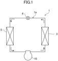
- a nineteenth aspect of the present disclosure is directed to a refrigeration apparatus including: the scroll compressor of any one of the first to eighteenth aspects; and a refrigerant circuit (1) through which a refrigerant compressed by the scroll compressor (10) flows.
- a scroll compressor (10) is provided in a refrigeration apparatus (1).
- the refrigeration apparatus (1) includes a refrigerant circuit (1a) filled with a refrigerant.
- the refrigerant circuit (1a) includes the scroll compressor (10), a radiator (3), a decompression mechanism (4), and an evaporator (5).
- the decompression mechanism (4) is, for example, an expansion valve.
- the refrigerant circuit (1a) performs a vapor compression refrigeration cycle.
- R513A or R1234yf is used as a refrigerant applicable to the scroll compressor (10).
- R513A is a refrigerant mixture consisting of HFC-134a and HFO-1234yf.
- R1234yf is a single-component refrigerant consisting of HFO-1234yf.
- the refrigeration apparatus (1) is an air conditioner.
- the air conditioner may be any of a cooling-only apparatus, a heating-only apparatus, or an air conditioner switchable between cooling and heating.
- the air conditioner has a switching mechanism (e.g., a four-way switching valve) configured to switch the direction of circulation of the refrigerant.
- the refrigeration apparatus (1) may be a water heater, a chiller unit, or a cooling apparatus configured to cool air in an internal space.
- the cooling apparatus cools the air in an internal space of a refrigerator, a freezer, a container, or the like.
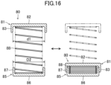
- the scroll compressor (10) includes a casing (20), an electric motor (30), and a compression mechanism (40).
- the casing (20) has a vertically oriented cylindrical shape, and is configured as a closed dome.
- the casing (20) houses the electric motor (30) and the compression mechanism (40).
- the electric motor (30) includes a stator (31) and a rotor (32).
- the stator (31) is fixed to the inner circumferential surface of the casing (20).
- the rotor (32) is disposed inside the stator (31).
- a drive shaft (11) passes through the rotor (32).
- the rotor (32) is fixed to the drive shaft (11).
- the casing (20) has, at its bottom, an oil reservoir (21).
- the oil reservoir (21) stores a lubricant.
- a suction pipe (12) is connected to an upper portion of the casing (20).
- a discharge pipe (not shown) is connected to a barrel of the casing (20).
- a housing (50) is fixed to the casing (20).
- the housing (50) is fixed to the inside of the casing (20) by, for example, shrink fitting.
- the housing (50) is located above the electric motor (30).
- the compression mechanism (40) is located above the housing (50).
- the housing (50) has a recess (53).
- the recess (53) is a recessed portion of the upper surface of the housing (50).
- An upper bearing (51) is located below the recess (53).
- the drive shaft (11) extends vertically along the center axis of the casing (20).
- the drive shaft (11) has a main shaft portion (14) and an eccentric portion (15).
- the eccentric portion (15) is provided at an upper end of the main shaft portion (14).
- the main shaft portion (14) has a lower portion rotatably supported by a lower bearing (22).
- the lower bearing (22) is fixed to the inner circumferential surface of the casing (20).
- the lower bearing (22) is provided with a positive-displacement pump (25), for example.
- the main shaft portion (14) has an upper portion passing through the housing (50) and rotatably supported by the upper bearing (51) of the housing (50).
- the compression mechanism (40) includes a fixed scroll (60) and a movable scroll (70).
- the fixed scroll (60) is fixed to the upper surface of the housing (50).
- the movable scroll (70) is arranged between the fixed scroll (60) and the housing (50).
- the fixed scroll (60) includes a fixed end plate (61), a fixed wrap (62), and an outer circumferential wall (63).
- the fixed wrap (62) is spiral.
- the fixed wrap (62) is formed on the lower surface of the fixed end plate (61).
- the outer circumferential wall (63) surrounds the outer periphery of the fixed wrap (62).
- the end surface of the fixed wrap (62) and the end surface of the outer circumferential wall (63) are substantially flush with each other.
- the fixed scroll (60) is fixed to the housing (50).
- the movable scroll (70) includes a movable end plate (71), a movable wrap (72), and a boss (73).
- the movable wrap (72) is spiral.
- the movable wrap (72) is formed on the upper surface of the movable end plate (71).
- the boss (73) is formed on a central portion of the lower surface of the movable end plate (71).
- the eccentric portion (15) of the drive shaft (11) is inserted into the boss (73), whereby the boss (73) is connected to the drive shaft (11).
- An Oldham coupling (not shown) is provided at an upper portion of the housing (50).
- the Oldham coupling blocks the rotation of the movable scroll (70) on its axis.
- the compression mechanism (40) has a fluid chamber (S) into which the refrigerant flows.
- the fluid chamber (S) is formed between the fixed scroll (60) and the movable scroll (70).
- the movable scroll (70) is placed so that the movable wrap (72) meshes with the fixed wrap (62) of the fixed scroll (60).
- the lower surface of the outer circumferential wall (63) of the fixed scroll (60) serves as a facing surface that faces the movable scroll (70).
- the upper surface of the movable end plate (71) of the movable scroll (70) serves as a facing surface that faces the fixed scroll (60).
- the fixed end plate (61) of the fixed scroll (60) has, at its center, an outlet (67).
- the high-pressure gas refrigerant discharged from the outlet (67) flows out into a lower space (24) via a passage (not shown) formed in the housing (50).
- the outer circumferential wall (63) of the fixed end plate (61) has a suction passage (64).
- the suction passage (64) extends vertically near the winding end of the fixed wrap (62).
- the upper end of the suction passage (64) is open to the upper surface of the fixed end plate (61).
- the lower end of the suction passage (64) is closed by a lower end portion of the fixed end plate (61).
- a lower end portion of the suction pipe (12) is connected to an upper end portion of the suction passage (64).
- a sidewall of the fixed end plate (61) has an inlet (65).
- the suction passage (64) communicates with the fluid chamber (S) via the inlet (65) (see FIG. 7 ).
- the refrigerant sucked from the suction pipe (12) is guided into the fluid chamber (S) via the suction passage (64) and the inlet (65).
- a suction check valve (80) is arranged in the suction passage (64).
- the suction check valve (80) closes the open end of the suction pipe (12) during a stop of the operation of the scroll compressor (10), thereby preventing the fluid in the fluid chamber (S) from flowing back toward the suction pipe (12). Details of the suction check valve (80) will be described later.
- An oil supply passage (16) is formed inside the drive shaft (11).
- the oil supply passage (16) extends vertically from the lower end to the upper end of the drive shaft (11).
- the pump (25) is connected to the lower end of the drive shaft (11). A lower end portion of the pump (25) is immersed in the oil reservoir (21).
- the pump (25) sucks up the lubricant from the oil reservoir (21) as the drive shaft (11) rotates, and transfers the lubricant to the oil supply passage (16).
- the oil supply passage (16) supplies the lubricant in the oil reservoir (21) to the sliding surfaces between the lower bearing (22) and the drive shaft (11) and the sliding surfaces between the upper bearing (51) and the drive shaft (11), and to the sliding surfaces between the boss (73) and the drive shaft (11).
- the oil supply passage (16) is open to the upper end surface of the drive shaft (11) and supplies the lubricant to above the drive shaft (11).
- the recess (53) of the housing (50) communicates with the oil supply passage (16) of the drive shaft (11) via the inside of the boss (73) of the movable scroll (70).
- the high-pressure lubricant is supplied to the recess (53), so that a high pressure equivalent to the discharge pressure of the compression mechanism (40) acts on the recess (53).
- the movable scroll (70) is pressed onto the fixed scroll (60) by the high pressure that acts on the recess (53).
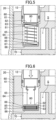
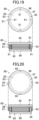
- the suction check valve (80) includes a valve body (81), a valve seat (85), and a compression spring (88).
- the valve body (81) closes the open end of the suction pipe (12) in a manner that allows opening and closing of the open end.
- the valve seat (85) faces, and is vertically spaced apart from, the valve body (81).
- the compression spring (88) is arranged between the valve body (81) and the valve seat (85) and biases the valve body (81) toward the open end of the suction pipe (12).
- the valve body (81) includes a first bottom portion (82) and a first circumferential wall (83).
- the first bottom portion (82) is in the shape of a disk.
- the first circumferential wall (83) stands toward the valve seat (85) along the peripheral portion of the first bottom portion (82).
- the valve seat (85) includes a second bottom portion (86) and a second circumferential wall (87).
- the second bottom portion (86) is in the shape of a disk.
- the second circumferential wall (87) stands toward the valve body (81) along the peripheral portion of the second bottom portion (86).
- the outside diameter D1 of the first circumferential wall (83) and the inside diameter d2 of the open end of the second circumferential wall (87) are set to satisfy the condition D1 ⁇ d2.
- the inside diameter of the second circumferential wall (87) of the valve seat (85) is set to a dimension that allows the accommodation of the first circumferential wall (83) of the valve body (81), and is therefore larger than the outside diameter of the compression spring (88) by the dimension.
- the compression spring (88) is welded and joined to the second bottom portion (86) of the valve seat (85) (see the hatched portions in FIG. 4 ).
- the first bottom portion (82) is formed into a size that allows closing of the open end of the suction pipe (12), i.e., a diameter larger than the inside diameter of the open end of the suction pipe (12).
- the first bottom portion (82) is formed into a size that allows reciprocation in the suction passage (64) in the direction of extension of the suction passage (64) (in the vertical direction in FIG. 5 ), i.e., a diameter smaller than the inside diameter of the suction passage (64).
- the outside diameter of the first circumferential wall (83) is formed into a dimension that allows reciprocation in the suction passage (64) in the direction of extension of the suction passage (64) (in the vertical direction in FIG. 5 ) together with the first bottom portion (82), i.e., smaller than the inside diameter of the suction passage (64).
- the first circumferential wall (83) extends along the inner wall of the suction passage (64).
- the inside diameter of the first circumferential wall (83) is formed into a dimension that allows accommodation of one end portion of the compression spring (88), i.e., larger than the outside diameter of the compression spring (88).
- the second bottom portion (86) is formed to have a diameter smaller than the inside diameter of the suction passage (64).
- the second bottom portion (86) is provided along the closed end surface (the lower end surface in FIG. 5 ) of the suction passage (64).
- the outside diameter of the second circumferential wall (87) is smaller than the inside diameter of the suction passage (64) and extends along the inner wall of the suction passage (64).
- the compression spring (88) in a contracted state is provided between the valve body (81) and the valve seat (85) to always apply, to the valve body (81), a biasing force for pressing the valve body (81) against the open end of the suction pipe (12).
- the compression spring (88) is configured to apply a biasing force to the valve body (81) even at a full-close position where the valve body (81) is pressed against the open end of the suction pipe (12).
- the opening degree of the valve body (81) refers to the position of the valve body (81) relative to the open end of the suction pipe (12): the opening degree is 0% at the full-close position where the valve body (81) closes the open end of the suction pipe (12); and the opening degree is 100% at a full-open position where the first circumferential wall (83) of the valve body (81) is housed on the inner side of the second circumferential wall (87) of the valve seat (85).
- valve body (81) closes the open end of the suction pipe (12) during a stop of the scroll compressor (10), thereby preventing the fluid in the fluid chamber (S) from flowing back toward the suction pipe (12).
- a portion of the first circumferential wall (83) of the valve body (81) is housed on the inner side of the second circumferential wall (87) of the valve seat (85), thereby making it possible to increase the passage area of the suction passage (64) by the portion housed. It is therefore possible to reduce suction pressure loss during operation of the scroll compressor (10) and improve the volume efficiency of the compressor.
- FIG. 2 when the electric motor (30) is activated, the drive shaft (11) to which the rotor (32) is fixed is driven to rotate. Since the rotation of the movable scroll (70) on its own axis is blocked by the Oldham coupling (not shown), the movable scroll (70) makes an orbiting motion about the axis of the drive shaft (11).
- the orbiting motion of the movable scroll (70) causes the refrigerant to be compressed in the fluid chamber (S).
- the high-pressure gas refrigerant compressed in the fluid chamber (S) is discharged from the outlet (67), and flows out into the lower space (24) via the passage (not shown) formed in the housing (50).
- the high-pressure gas refrigerant in the lower space (24) is discharged outside the casing (20) via the discharge pipe (13).
- the rotation of the drive shaft (11) causes the high-pressure lubricant in the oil reservoir (21) to be sucked up by the pump (25).
- the lubricant sucked up flows upward through the oil supply passage (16) of the drive shaft (11) and flows out from the opening at the upper end of the eccentric portion (15) of the drive shaft (11) into the inside of the boss (73) of the movable scroll (70).
- the lubricant supplied to the boss (73) flows out into the recess (53) of the housing (50) through the gap between the eccentric portion (15) of the drive shaft (11) and the boss (73). Accordingly, the recess (53) of the housing (50) has a high pressure equivalent to the discharge pressure of the compression mechanism (40). The high pressure of the recess (53) presses the movable scroll (70) onto the fixed scroll (60).
- one of the first circumferential wall (83) of the valve body (81) or the second circumferential wall (87) of the valve seat (85) is set to have an outside diameter smaller than the inside diameter of the open end of the other circumferential wall, thereby making it possible to house one of the circumferential walls on the inner side of the other circumferential wall.
- the first circumferential wall (83) of the valve body (81) can be housed on the inner side of the second circumferential wall (87) of the valve seat (85), thereby making it possible to keep the passage area of the suction passage (64) from decreasing and reduce suction pressure loss during operation of the scroll compressor (10).
- the volume efficiency of the compressor can be improved even if R513A, which is an intermediate/low pressure refrigerant, is used.
- This embodiment allows an increase in the passage area of the suction passage (64) by the portion of the circumferential wall of the valve body (81) or the valve seat (85) which has been housed, thereby making it possible to reduce suction pressure loss during operation of the scroll compressor (10) and improve the volume efficiency of the compressor.
- the volume efficiency of the compressor can be improved even if R1234yf, which is an intermediate/low pressure refrigerant, is used.
- the outside diameter of the first circumferential wall (83) of the valve body (81) is smaller than the inside diameter of the open end of the second circumferential wall (87) of the valve seat (85).
- a portion of the first circumferential wall (83) of the valve body (81) is housed on the inner side of the second circumferential wall (87) of the valve seat (85).
- the outer circumferential surface of the first circumferential wall (83) has a plurality of outer grooves (91).
- the outer grooves (91) extend along the direction of expansion and contraction of the compression spring (88).
- four outer grooves (91) are arranged so as to be spaced apart from one another in the circumferential direction.
- the number of the outer grooves (91) is an example and is not limited thereto.
- the area of contact between the first circumferential wall (83) and the second circumferential wall (87) is reduced, so that it is possible to reduce the chances of the valve body (81) not returning toward the suction pipe (12) due to the viscosity of the lubricant between the first circumferential wall (83) and the second circumferential wall (87) during a stop of the scroll compressor (10).
- the outside diameter of the first circumferential wall (83) of the valve body (81) is smaller than the inside diameter of the open end of the second circumferential wall (87) of the valve seat (85).
- a portion of the first circumferential wall (83) of the valve body (81) is housed on the inner side of the second circumferential wall (87) of the valve seat (85).
- the inner circumferential surface of the second circumferential wall (87) has a plurality of inner grooves (92).
- the inner grooves (92) extend along the direction of expansion and contraction of the compression spring (88).
- four inner grooves (92) are arranged so as to spaced apart from one another in the circumferential direction.
- the number of the inner grooves (92) is an example and is not limited thereto.
- the area of contact between the first circumferential wall (83) and the second circumferential wall (87) is reduced, so that it is possible to reduce the chances of the valve body (81) not returning toward the suction pipe (12) due to the viscosity of the lubricant between the first circumferential wall (83) and the second circumferential wall (87) during a stop of the scroll compressor (10).
- the outside diameter of the first circumferential wall (83) of the valve body (81) is smaller than the inside diameter of the open end of the second circumferential wall (87) of the valve seat (85).
- a portion of the first circumferential wall (83) of the valve body (81) is housed on the inner side of the second circumferential wall (87) of the valve seat (85).
- a tapered portion (93) is formed on the inner circumferential surface of the second circumferential wall (87).
- the tapered portion (93) is inclined such that the inside diameter of the second circumferential wall (87) increases gradually toward the valve body (81).
- the area of contact between the first circumferential wall (83) and the second circumferential wall (87) is reduced, so that it is possible to reduce the chances of the valve body (81) not returning toward the suction pipe (12) due to the viscosity of the lubricant between the first circumferential wall (83) and the second circumferential wall (87) during a stop of the scroll compressor (10).
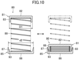
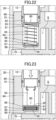
- connection passage (94) the outer circumferential wall (63) of the fixed end plate (61) has a connection passage (94).
- One end of the connection passage (94) is open to a mounting surface in the suction passage (64) on which the valve seat (85) is mounted.
- the other end of the connection passage (94) is open into the fluid chamber (S).
- the suction passage (64) and the fluid chamber (S) are connected together via the connection passage (94).
- the second bottom portion (86) of the valve seat (85) has a communication hole (95).
- the communication hole (95) communicates with the connection passage (94) in a state in which the valve seat (85) is mounted on the mounting surface in the suction passage (64).
- valve body (81) moves toward the valve seat (85) against the biasing force of the compression spring (88), and the first circumferential wall (83) is housed on the inner side of the second circumferential wall (87). Then, during a stop of the scroll compressor (10), the refrigerant pushing the valve body (81) is no longer sucked, and the valve body (81) is moved by the biasing force of the compression spring (88) to the position at which the valve body (81) closes the open end of the suction pipe (12). At this moment, the valve body (81) may sometimes not return toward the suction pipe (12) due to the viscosity of the lubricant between the first circumferential wall (83) and the second circumferential wall (87) during the stop of the scroll compressor (10)
- the refrigerant in the fluid chamber (S) flows between the valve body (81) and the valve seat (85) via the connection passage (94) and the communication hole (95) during the stop of the scroll compressor (10) (see the hollow arrows in FIG. 11 ).
- valve body (81) is pushed up by the refrigerant that has flowed through the connection passage (94) and the communication hole (95). It is this possible to return the valve body (81) to the full-close position (see FIG. 12 ).
- the refrigerant in the fluid chamber (S) flows between the valve body (81) and the valve seat (85) via the connection passage (94) and the communication hole (95) during a stop of the scroll compressor (10), which makes it possible to return the valve body (81) toward the suction pipe (12).
- a surface of the second bottom portion (86) of the valve seat (85) near the valve body (81) has a spring housing portion (96).
- the spring housing portion (96) is a recessed portion of the upper surface of the second bottom portion (86).
- the inside diameter of the spring housing portion (96) is larger than the outside diameter of the compression spring (88).
- the spring housing portion (96) houses a lower end portion of the compression spring (88).
- the compression spring (88) is welded and joined to the second bottom portion (86) in the spring housing portion (96).
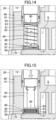
- the suction passage (64) extends along the axial direction of the suction pipe (12) and is open to a surface of the fixed scroll (60) that faces the movable scroll (70).
- the outer circumferential surface of the valve seat (85) has a recess around its entire perimeter.
- a seal ring (97) is fitted into the recess.
- the valve seat (85) is fitted into the lower opening of the suction passage (64) to close the opening.
- the valve seat (85) may be press-fitted into the lower opening of the suction passage (64) without providing the seal ring (97).
- the inside diameter d3 of the suction passage (64) and the inside diameter d2 of the open end of the second circumferential wall (87) are set to satisfy the condition d3 ⁇ d2.
- valve body (81) moves along the inner circumferential surface of the suction passage (64) when the valve body (81) moves toward the valve seat (85) against the biasing force of the compression spring (88).
- the valve body (81) is therefore less likely to incline.
- the outside diameter of the first circumferential wall (83) of the valve body (81) is smaller than the inside diameter of the open end of the second circumferential wall (87) of the valve seat (85).
- the first circumferential wall (83) of the valve body (81) has an outside diameter substantially equal to the inside diameter of the suction passage (64), the first circumferential wall (83) can be housed on the inner side of the second circumferential wall (87). It is thus possible to move the valve body (81) smoothly along the suction passage (64).
- a suction check valve (80) includes a valve body (81), a valve seat (85), and a compression spring (88).
- the valve body (81) closes the open end of the suction pipe (12) in a manner that allows opening and closing of the open end.
- the valve seat (85) faces, and is vertically spaced apart from, the valve body (81).
- the compression spring (88) is arranged between the valve body (81) and the valve seat (85) and biases the valve body (81) toward the open end of the suction pipe (12).
- the valve body (81) includes a first bottom portion (82) and a first circumferential wall (83).
- the first bottom portion (82) is in the shape of a disk.
- the first circumferential wall (83) stands toward the valve seat (85) along the peripheral portion of the first bottom portion (82).
- the valve seat (85) includes a second bottom portion (86) and a second circumferential wall (87).
- the second bottom portion (86) is in the shape of a disk.
- the second circumferential wall (87) stands toward the valve body (81) along the peripheral portion of the second bottom portion (86).
- the inside diameter d1 of the open end of the first circumferential wall (83) and the outside diameter D2 of the second circumferential wall (87) are set to satisfy the condition D2 ⁇ d1.
- the inside diameter of the first circumferential wall (83) of the valve body (81) is set to a dimension that allows the accommodation of the second circumferential wall (87) of the valve seat (85), and is therefore larger than the outside diameter of the compression spring (88) by the dimension.
- the compression spring (88) is welded and joined to the first bottom portion (82) of the valve body (81).
- valve body (81) closes the open end of the suction pipe (12) during a stop of the scroll compressor (10), thereby preventing the fluid in the fluid chamber (S) from flowing back toward the suction pipe (12).
- a portion of the second circumferential wall (87) of the valve seat (85) is housed on the inner side of the first circumferential wall (83) of the valve body (81), thereby making it possible to increase the passage area of the suction passage (64) by the portion housed. It is therefore possible to reduce suction pressure loss during operation of the scroll compressor (10) and improve the volume efficiency of the compressor.
- the second circumferential wall (87) of the valve seat (85) can be housed on the inner side of the first circumferential wall (83) of the valve body (81), thereby making it possible to keep the passage area of the suction passage (64) from decreasing and reduce suction pressure loss during operation of the scroll compressor (10).
- the outside diameter of the second circumferential wall (87) of the valve seat (85) is smaller than the inside diameter of the open end of the first circumferential wall (83) of the valve body (81).
- the outer circumferential surface of the second circumferential wall (87) has a plurality of outer grooves (91).
- the outer grooves (91) extend along the direction of expansion and contraction of the compression spring (88).
- four outer grooves (91) are arranged so as to be spaced apart from one another in the circumferential direction.
- the number of the outer grooves (91) is an example and is not limited thereto.
- the area of contact between the first circumferential wall (83) and the second circumferential wall (87) is reduced, so that it is possible to reduce the chances of the valve body (81) not returning toward the suction pipe (12) due to the viscosity of the lubricant between the first circumferential wall (83) and the second circumferential wall (87) during a stop of the scroll compressor (10).
- the outside diameter of the second circumferential wall (87) of the valve seat (85) is smaller than the inside diameter of the open end of the first circumferential wall (83) of the valve body (81).
- the inner circumferential surface of the first circumferential wall (83) has a plurality of inner grooves (92).
- the inner grooves (92) extend along the direction of expansion and contraction of the compression spring (88).
- four inner grooves (92) are arranged so as to spaced apart from one another in the circumferential direction.
- the number of the inner grooves (92) is an example and is not limited thereto.
- the area of contact between the first circumferential wall (83) and the second circumferential wall (87) is reduced, so that it is possible to reduce the chances of the valve body (81) not returning toward the suction pipe (12) due to the viscosity of the lubricant between the first circumferential wall (83) and the second circumferential wall (87) during a stop of the scroll compressor (10).
- a surface of the first bottom portion (82) of the valve body (81) near the valve seat (85) has a spring housing portion (96).
- the spring housing portion (96) is a recessed portion of the lower surface of the first bottom portion (82).
- the inside diameter of the spring housing portion (96) is larger than the outside diameter of the compression spring (88).
- the spring housing portion (96) houses an upper end portion of the compression spring (88).
- the compression spring (88) is welded and joined to the first bottom portion (82) in the spring housing portion (96).
- the bottom surface in the suction passage (64) has a valve seat housing portion (98).
- the valve seat housing portion (98) is a recessed portion of the bottom surface of the suction passage (64).
- the valve seat (85) is housed in the valve seat housing portion (98).
- the outside diameter of the valve body (81) is smaller than the inside diameter of the suction passage (64). As illustrated in FIG. 23 , during operation of the scroll compressor (10), the valve body (81) moves along the inner circumferential surface of the suction passage (64) when the valve body (81) moves toward the valve seat (85) against the biasing force of the compression spring (88). The valve body (81) is therefore less likely to incline.
- the outside diameter of the second circumferential wall (87) of the valve seat (85) is smaller than the inside diameter of the open end of the first circumferential wall (83) of the valve body (81).
- the first embodiment may be configured such that the bottom surface in the suction passage (64) has a valve seat housing portion (98) which is a recessed portion and houses the valve seat (85). It is this possible to restrict the movement of the valve seat (85) in the suction passage (64) in the radial direction.
- the second embodiment may be configured such that the fixed scroll (60) has a connection passage (94) having one end open to the mounting surface on which the valve seat (85) is mounted, and the other end connected to the fluid chamber (S), and that the second bottom portion (86) has a communication hole (95) that communicates with the connection passage (94).
- the refrigerant in the fluid chamber (S) flows between the valve body (81) and the valve seat (85) via the connection passage (94) and the communication hole (95) during a stop of the scroll compressor (10), which makes it possible to return the valve body (81) toward the suction pipe (12).
- the second embodiment may also be configured such that the suction passage (64) extends along the axial direction of the suction pipe (12) and is open to the surface of the fixed scroll (60) facing the movable scroll (70), and that the valve seat (85) is fitted into the opening of the suction passage (64) to close the opening. It is this possible to restrict the movement of the valve seat (85) in the suction passage (64) in the radial direction.
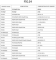
- R513A and R1234yf have been raised as examples of the refrigerant applicable to the scroll compressor (10).
- R513A is a refrigerant mixture containing a hydrofluoroolefin (HFO) refrigerant.
- R1234yf is an HFO refrigerant.
- the refrigerant applicable to the scroll compressor (10) is not limited to R513A and R1234yf.
- Examples of the HFO refrigerant or the refrigerant mixture containing the HFO refrigerant as the refrigerant applicable to the scroll compressor (10) include single-component refrigerants and refrigerant mixtures shown in the list of FIG. 24 .
- the present disclosure is useful for a scroll compressor and a refrigeration apparatus.
Landscapes
- Engineering & Computer Science (AREA)
- Mechanical Engineering (AREA)
- General Engineering & Computer Science (AREA)
- Physics & Mathematics (AREA)
- Thermal Sciences (AREA)
- Rotary Pumps (AREA)
- Applications Or Details Of Rotary Compressors (AREA)
- Compressor (AREA)
- Check Valves (AREA)
Applications Claiming Priority (2)
| Application Number | Priority Date | Filing Date | Title |
|---|---|---|---|
| JP2021176255 | 2021-10-28 | ||
| PCT/JP2022/038188 WO2023074389A1 (ja) | 2021-10-28 | 2022-10-13 | スクロール圧縮機及び冷凍装置 |
Publications (3)
| Publication Number | Publication Date |
|---|---|
| EP4403776A1 true EP4403776A1 (de) | 2024-07-24 |
| EP4403776A4 EP4403776A4 (de) | 2025-01-08 |
| EP4403776B1 EP4403776B1 (de) | 2025-12-17 |
Family
ID=86157935
Family Applications (1)
| Application Number | Title | Priority Date | Filing Date |
|---|---|---|---|
| EP22886718.0A Active EP4403776B1 (de) | 2021-10-28 | 2022-10-13 | Spiralverdichter und kühlapparat |
Country Status (6)
| Country | Link |
|---|---|
| US (1) | US12297830B2 (de) |
| EP (1) | EP4403776B1 (de) |
| JP (1) | JP7277848B1 (de) |
| CN (1) | CN118076810B (de) |
| ES (1) | ES3059879T3 (de) |
| WO (1) | WO2023074389A1 (de) |
Family Cites Families (17)
| Publication number | Priority date | Publication date | Assignee | Title |
|---|---|---|---|---|
| JPS5093627U (de) * | 1973-12-27 | 1975-08-06 | ||
| JPS6093627U (ja) * | 1983-11-30 | 1985-06-26 | 安藤電気株式会社 | ウエハの搬送機構 |
| JPS60142082A (ja) * | 1983-12-28 | 1985-07-27 | Matsushita Electric Ind Co Ltd | ベ−ン回転式圧縮機の吸入逆流防止装置 |
| JPH0643515Y2 (ja) * | 1986-06-16 | 1994-11-14 | 三菱電機株式会社 | 2シリンダロータリ圧縮機 |
| JPH04350377A (ja) * | 1991-05-29 | 1992-12-04 | Daikin Ind Ltd | スクロール形圧縮機 |
| US6179589B1 (en) * | 1999-01-04 | 2001-01-30 | Copeland Corporation | Scroll machine with discus discharge valve |
| DE102006019543A1 (de) * | 2006-04-27 | 2007-10-31 | Schaeffler Kg | Plattenrückschlagventil mit seitlicher Abströmung und Steuerkante |
| JP2009281345A (ja) * | 2008-05-26 | 2009-12-03 | Daikin Ind Ltd | スクロール圧縮機 |
| JP5235962B2 (ja) * | 2010-09-28 | 2013-07-10 | 三菱電機株式会社 | スクロール圧縮機 |
| JP2016169701A (ja) * | 2015-03-13 | 2016-09-23 | 株式会社豊田自動織機 | 可変容量型圧縮機 |
| JP2017115687A (ja) * | 2015-12-24 | 2017-06-29 | 株式会社豊田自動織機 | 圧縮機の逆止弁 |
| US10746441B2 (en) * | 2016-03-07 | 2020-08-18 | Daikin Applied Americas Inc. | Heat exchanger |
| JP6760180B2 (ja) * | 2017-03-30 | 2020-09-23 | 株式会社豊田自動織機 | 圧縮機 |
| JP6489166B2 (ja) * | 2017-07-05 | 2019-03-27 | ダイキン工業株式会社 | スクロール圧縮機 |
| JP2020007945A (ja) * | 2018-07-05 | 2020-01-16 | ダイキン工業株式会社 | スクロール圧縮機 |
| CN209704839U (zh) * | 2019-02-22 | 2019-11-29 | 江森自控日立万宝压缩机(广州)有限公司 | 一种具有新型止回阀的涡旋压缩机 |
| JP2024142082A (ja) | 2023-03-29 | 2024-10-10 | 日本碍子株式会社 | 車両用空調システム、及び空調デバイスの再生方法 |
-
2022
- 2022-10-13 WO PCT/JP2022/038188 patent/WO2023074389A1/ja not_active Ceased
- 2022-10-13 CN CN202280063282.2A patent/CN118076810B/zh active Active
- 2022-10-13 ES ES22886718T patent/ES3059879T3/es active Active
- 2022-10-13 JP JP2022164441A patent/JP7277848B1/ja active Active
- 2022-10-13 EP EP22886718.0A patent/EP4403776B1/de active Active
-
2024
- 2024-04-26 US US18/648,038 patent/US12297830B2/en active Active
Also Published As
| Publication number | Publication date |
|---|---|
| WO2023074389A1 (ja) | 2023-05-04 |
| ES3059879T3 (en) | 2026-03-24 |
| US20240271620A1 (en) | 2024-08-15 |
| CN118076810B (zh) | 2024-09-10 |
| JP2023074470A (ja) | 2023-05-29 |
| EP4403776A4 (de) | 2025-01-08 |
| EP4403776B1 (de) | 2025-12-17 |
| US12297830B2 (en) | 2025-05-13 |
| JP7277848B1 (ja) | 2023-05-19 |
| CN118076810A (zh) | 2024-05-24 |
Similar Documents
| Publication | Publication Date | Title |
|---|---|---|
| US7462021B2 (en) | Rotary compressor, and car air conditioner and heat pump type water heater using the compressor | |
| US8834139B2 (en) | Lubrication of a scroll compressor | |
| US20080152526A1 (en) | Vapor injection system for a scroll compressor | |
| CN101165350A (zh) | 涡旋压缩机以及使用其的冷冻循环 | |
| KR20190097309A (ko) | 액시얼 플럭스 모터를 가진 스크롤 압축기 | |
| EP4403776B1 (de) | Spiralverdichter und kühlapparat | |
| US20090116977A1 (en) | Compressor With Muffler | |
| JP7119812B2 (ja) | 圧縮機 | |
| US12078173B2 (en) | Compressor having lubrication system | |
| WO2017141309A1 (ja) | ロータリ圧縮機 | |
| EP4372229A1 (de) | Spiralverdichter und kühlvorrichtung | |
| US20260002533A1 (en) | Rotary compressor and refrigeration apparatus | |
| JP7139718B2 (ja) | 圧縮機 | |
| EP4170172A1 (de) | Spiralverdichter | |
| JP2025115564A (ja) | スクロール圧縮機及び冷凍装置 | |
| JP2018168715A (ja) | スクロール圧縮機 | |
| JP2024013789A (ja) | 回転式圧縮機及び冷凍装置 | |
| JP2024048814A (ja) | 密閉型ロータリ圧縮機及びこれを備えた冷蔵庫 | |
| CN119467324A (zh) | 压缩机 | |
| JP2023030778A (ja) | スクロール圧縮機及び冷凍装置 | |
| CN116917624A (zh) | 涡旋压缩机以及制冷循环装置 | |
| KR20000017022A (ko) | 회전압축기, 이 압축기를 사용한 냉동사이클 및 이 압축기를사용한 냉장고 |
Legal Events
| Date | Code | Title | Description |
|---|---|---|---|
| STAA | Information on the status of an ep patent application or granted ep patent |
Free format text: STATUS: THE INTERNATIONAL PUBLICATION HAS BEEN MADE |
|
| PUAI | Public reference made under article 153(3) epc to a published international application that has entered the european phase |
Free format text: ORIGINAL CODE: 0009012 |
|
| STAA | Information on the status of an ep patent application or granted ep patent |
Free format text: STATUS: REQUEST FOR EXAMINATION WAS MADE |
|
| 17P | Request for examination filed |
Effective date: 20240416 |
|
| AK | Designated contracting states |
Kind code of ref document: A1 Designated state(s): AL AT BE BG CH CY CZ DE DK EE ES FI FR GB GR HR HU IE IS IT LI LT LU LV MC ME MK MT NL NO PL PT RO RS SE SI SK SM TR |
|
| A4 | Supplementary search report drawn up and despatched |
Effective date: 20241206 |
|
| RIC1 | Information provided on ipc code assigned before grant |
Ipc: F04C 29/12 20060101ALI20241202BHEP Ipc: F04C 18/02 20060101AFI20241202BHEP |
|
| DAV | Request for validation of the european patent (deleted) | ||
| DAX | Request for extension of the european patent (deleted) | ||
| P01 | Opt-out of the competence of the unified patent court (upc) registered |
Free format text: CASE NUMBER: APP_1063/2025 Effective date: 20250108 |
|
| GRAP | Despatch of communication of intention to grant a patent |
Free format text: ORIGINAL CODE: EPIDOSNIGR1 |
|
| STAA | Information on the status of an ep patent application or granted ep patent |
Free format text: STATUS: GRANT OF PATENT IS INTENDED |
|
| INTG | Intention to grant announced |
Effective date: 20250916 |
|
| RIN1 | Information on inventor provided before grant (corrected) |
Inventor name: ARAKANE, TAIGA Inventor name: SHIMOZONO, NAOKI Inventor name: YOKOYAMA, TOMOMI Inventor name: YAMAMOTO, TAKAFUMI |
|
| GRAS | Grant fee paid |
Free format text: ORIGINAL CODE: EPIDOSNIGR3 |
|
| GRAA | (expected) grant |
Free format text: ORIGINAL CODE: 0009210 |
|
| STAA | Information on the status of an ep patent application or granted ep patent |
Free format text: STATUS: THE PATENT HAS BEEN GRANTED |
|
| AK | Designated contracting states |
Kind code of ref document: B1 Designated state(s): AL AT BE BG CH CY CZ DE DK EE ES FI FR GB GR HR HU IE IS IT LI LT LU LV MC ME MK MT NL NO PL PT RO RS SE SI SK SM TR |
|
| REG | Reference to a national code |
Ref country code: CH Ref legal event code: F10 Free format text: ST27 STATUS EVENT CODE: U-0-0-F10-F00 (AS PROVIDED BY THE NATIONAL OFFICE) Effective date: 20251217 Ref country code: GB Ref legal event code: FG4D |
|
| REG | Reference to a national code |
Ref country code: DE Ref legal event code: R096 Ref document number: 602022027213 Country of ref document: DE |
|
| REG | Reference to a national code |
Ref country code: ES Ref legal event code: FG2A Ref document number: 3059879 Country of ref document: ES Kind code of ref document: T3 Effective date: 20260324 |
|
| REG | Reference to a national code |
Ref country code: LT Ref legal event code: MG9D |
|
| PG25 | Lapsed in a contracting state [announced via postgrant information from national office to epo] |
Ref country code: NO Free format text: LAPSE BECAUSE OF FAILURE TO SUBMIT A TRANSLATION OF THE DESCRIPTION OR TO PAY THE FEE WITHIN THE PRESCRIBED TIME-LIMIT Effective date: 20260317 |
|
| PG25 | Lapsed in a contracting state [announced via postgrant information from national office to epo] |
Ref country code: FI Free format text: LAPSE BECAUSE OF FAILURE TO SUBMIT A TRANSLATION OF THE DESCRIPTION OR TO PAY THE FEE WITHIN THE PRESCRIBED TIME-LIMIT Effective date: 20251217 Ref country code: HR Free format text: LAPSE BECAUSE OF FAILURE TO SUBMIT A TRANSLATION OF THE DESCRIPTION OR TO PAY THE FEE WITHIN THE PRESCRIBED TIME-LIMIT Effective date: 20251217 |
|
| PG25 | Lapsed in a contracting state [announced via postgrant information from national office to epo] |
Ref country code: RS Free format text: LAPSE BECAUSE OF FAILURE TO SUBMIT A TRANSLATION OF THE DESCRIPTION OR TO PAY THE FEE WITHIN THE PRESCRIBED TIME-LIMIT Effective date: 20260317 |
|
| REG | Reference to a national code |
Ref country code: NL Ref legal event code: MP Effective date: 20251217 |
|
| PG25 | Lapsed in a contracting state [announced via postgrant information from national office to epo] |
Ref country code: LV Free format text: LAPSE BECAUSE OF FAILURE TO SUBMIT A TRANSLATION OF THE DESCRIPTION OR TO PAY THE FEE WITHIN THE PRESCRIBED TIME-LIMIT Effective date: 20251217 |