EP4403785A1 - Mécanisme rotatif et dispositif électronique pliable - Google Patents
Mécanisme rotatif et dispositif électronique pliable Download PDFInfo
- Publication number
- EP4403785A1 EP4403785A1 EP23810788.2A EP23810788A EP4403785A1 EP 4403785 A1 EP4403785 A1 EP 4403785A1 EP 23810788 A EP23810788 A EP 23810788A EP 4403785 A1 EP4403785 A1 EP 4403785A1
- Authority
- EP
- European Patent Office
- Prior art keywords
- swing arm
- synchronization
- damping body
- state
- rotating mechanism
- Prior art date
- Legal status (The legal status is an assumption and is not a legal conclusion. Google has not performed a legal analysis and makes no representation as to the accuracy of the status listed.)
- Granted
Links
Images








Classifications
-
- G—PHYSICS
- G06—COMPUTING OR CALCULATING; COUNTING
- G06F—ELECTRIC DIGITAL DATA PROCESSING
- G06F1/00—Details not covered by groups G06F3/00 - G06F13/00 and G06F21/00
- G06F1/16—Constructional details or arrangements
- G06F1/1613—Constructional details or arrangements for portable computers
- G06F1/1633—Constructional details or arrangements of portable computers not specific to the type of enclosures covered by groups G06F1/1615 - G06F1/1626
- G06F1/1675—Miscellaneous details related to the relative movement between the different enclosures or enclosure parts
- G06F1/1681—Details related solely to hinges
-
- F—MECHANICAL ENGINEERING; LIGHTING; HEATING; WEAPONS; BLASTING
- F16—ENGINEERING ELEMENTS AND UNITS; GENERAL MEASURES FOR PRODUCING AND MAINTAINING EFFECTIVE FUNCTIONING OF MACHINES OR INSTALLATIONS; THERMAL INSULATION IN GENERAL
- F16C—SHAFTS; FLEXIBLE SHAFTS; ELEMENTS OR CRANKSHAFT MECHANISMS; ROTARY BODIES OTHER THAN GEARING ELEMENTS; BEARINGS
- F16C11/00—Pivots; Pivotal connections
- F16C11/04—Pivotal connections
-
- F—MECHANICAL ENGINEERING; LIGHTING; HEATING; WEAPONS; BLASTING
- F16—ENGINEERING ELEMENTS AND UNITS; GENERAL MEASURES FOR PRODUCING AND MAINTAINING EFFECTIVE FUNCTIONING OF MACHINES OR INSTALLATIONS; THERMAL INSULATION IN GENERAL
- F16C—SHAFTS; FLEXIBLE SHAFTS; ELEMENTS OR CRANKSHAFT MECHANISMS; ROTARY BODIES OTHER THAN GEARING ELEMENTS; BEARINGS
- F16C11/00—Pivots; Pivotal connections
- F16C11/04—Pivotal connections
- F16C11/10—Arrangements for locking
-
- G—PHYSICS
- G06—COMPUTING OR CALCULATING; COUNTING
- G06F—ELECTRIC DIGITAL DATA PROCESSING
- G06F1/00—Details not covered by groups G06F3/00 - G06F13/00 and G06F21/00
- G06F1/16—Constructional details or arrangements
- G06F1/1613—Constructional details or arrangements for portable computers
- G06F1/1615—Constructional details or arrangements for portable computers with several enclosures having relative motions, each enclosure supporting at least one I/O or computing function
- G06F1/1616—Constructional details or arrangements for portable computers with several enclosures having relative motions, each enclosure supporting at least one I/O or computing function with folding flat displays, e.g. laptop computers or notebooks having a clamshell configuration, with body parts pivoting to an open position around an axis parallel to the plane they define in closed position
-
- H—ELECTRICITY
- H04—ELECTRIC COMMUNICATION TECHNIQUE
- H04M—TELEPHONIC COMMUNICATION
- H04M1/00—Substation equipment, e.g. for use by subscribers
- H04M1/02—Constructional features of telephone sets
-
- H—ELECTRICITY
- H04—ELECTRIC COMMUNICATION TECHNIQUE
- H04M—TELEPHONIC COMMUNICATION
- H04M1/00—Substation equipment, e.g. for use by subscribers
- H04M1/02—Constructional features of telephone sets
- H04M1/0202—Portable telephone sets, e.g. cordless phones, mobile phones or bar type handsets
- H04M1/0206—Portable telephones comprising a plurality of mechanically joined movable body parts, e.g. hinged housings
- H04M1/0208—Portable telephones comprising a plurality of mechanically joined movable body parts, e.g. hinged housings characterized by the relative motions of the body parts
- H04M1/0214—Foldable telephones, i.e. with body parts pivoting to an open position around an axis parallel to the plane they define in closed position
- H04M1/0216—Foldable in one direction, i.e. using a one degree of freedom hinge
- H04M1/022—The hinge comprising two parallel pivoting axes
-
- H—ELECTRICITY
- H05—ELECTRIC TECHNIQUES NOT OTHERWISE PROVIDED FOR
- H05K—PRINTED CIRCUITS; CASINGS OR CONSTRUCTIONAL DETAILS OF ELECTRIC APPARATUS; MANUFACTURE OF ASSEMBLAGES OF ELECTRICAL COMPONENTS
- H05K5/00—Casings, cabinets or drawers for electric apparatus
- H05K5/02—Details
- H05K5/0217—Mechanical details of casings
- H05K5/0226—Hinges
Definitions
- This application relates to the field of electronic product technologies, and in particular, to a rotating mechanism and a foldable electronic device.
- This application provides a rotating mechanism and a foldable electronic device, to resolve problems that assembly difficulty of the rotating mechanism in the conventional technology is great because of excessive parts and costs of the product are increased.
- this application provides a rotating mechanism, including a fastening base, a first synchronization swing arm, a second synchronization swing arm, and a damping member.
- the first synchronization swing arm and the second synchronization swing arm are respectively mounted on two opposite sides of the fastening base in a width direction and are rotatably connected to the fastening base.
- the damping member includes a baffle plate and a damping body, one end of the damping body is connected to the first synchronization swing arm, the other end of the damping body is connected to the baffle plate, two opposite ends of the damping body are disposed along a length direction of the fastening base, and the damping body is made of a shape memory alloy.
- the damping body When the first synchronization swing arm and the second synchronization swing arm are in a folded state, the damping body is in a first state, where the first state is an initial state of the damping body.
- the first synchronization swing arm is rotated relative to the fastening base to drive one end of the damping body to rotate, the first synchronization swing arm and the second synchronization swing arm are relatively unfolded from the folded state, and the damping body is in a second state, where the second state is that the damping body is deformed and generates damping force relative to the first synchronization swing arm.
- the first synchronization swing arm and the second synchronization swing arm can be rotated relative to each other under the action of external force exerted on the rotating mechanism.
- the first synchronization swing arm is rotated, one end of the damping body is driven to rotate relative to the fastening base.
- One end that is of the damping body and that is connected to the baffle plate remains stationary relative to the fastening base.
- the damping body is deformed when the first synchronization swing arm is rotated. Because the damping body is made of a shape memory alloy, the damping body can generate damping force during deformation.
- the damping body is in the first state, the first synchronization swing arm and the second synchronization swing arm are relatively folded, and the rotating mechanism is in a folded state.
- the first synchronization swing arm is rotated to exert external force on the damping body, the damping body is deformed from the first state to the second state, and the damping body generates damping force resisting the external force during deformation under stress, to provide damping hand feeling.
- the damping body when the first synchronization swing arm and the second synchronization swing arm are in a flattened state, the damping body is in a third state, where the third state is that the damping body is in a deformed state and that the damping body generates damping force relative to the first synchronization swing arm.
- the damping body when the rotating mechanism is in a flattened state, the first synchronization swing arm and the second synchronization swing arm are in the flattened state, and the damping body is in the third state.
- the damping body When the damping body is in the third state, the damping body can keep the first synchronization swing arm and the second synchronization swing arm in the flattened state, thereby implementing flattening positioning of the rotating mechanism.
- the damping body in the third state When the rotating mechanism in the flattened state is exerted by external force, the damping body in the third state generates damping force resisting the external force. When the external force reaches a specific value, the damping body is deformed again from the third state and provides damping hand feeling.
- a deformation amount of the damping body in the second state is less than that in the third state.
- the damping body when the rotating mechanism is in a folded state, the damping body is in the first state.
- the damping body When the rotating mechanism is in a flattened state, the damping body is in the third state.
- the damping body When the rotating mechanism is in a state between a folded state and an unfolded state, the damping body is in the second state.
- the first state of the damping body is a non-deformed state, that is, the initial state of the damping body.
- the damping force of the damping body enables the first synchronization swing arm and the second synchronization swing arm to be positioned relative to the fastening base.
- the damping body is deformed when the first synchronization swing arm is rotated, and after the first synchronization swing arm stops being rotated, the damping body can keep in a deformed state.
- the damping body may be in the second state or the third state.
- the damping body can keep stable in the second state or the third state, so that the rotating mechanism can keep hovering. It can be understood that the damping body can implement hovering of the first synchronization swing arm in the second state (at any angle in the unfolding process) or the third state, to implement hovering of the rotating mechanism. In this way, no other positioning structures need to be disposed, occupied space is reduced, and a structure is simplified.
- the damping body has a first intermediate state, a deformation amount in the first intermediate state is less than that in the third state, and the first preset temperature is applied to the damping body in the first intermediate state, so that a microstructure of the damping body changes at the first preset temperature, and the damping body changes from the first intermediate state to the third state.
- the deformation amount of the damping body in the first intermediate state may be a deformation amount generated by rebound of the damping body in the third state.
- the rotating mechanism is relatively unfolded from the folded state under the action of external force
- the first synchronization swing arm and the second synchronization swing arm are rotated relative to each other, and the damping body is deformed.
- the first synchronization swing arm and the second synchronization swing arm are relatively flattened, that is, after the damping body reaches the third state, the external force is removed, the damping body rebounds slightly, and the deformation amount of the damping body decreases.
- the damping body is in the first intermediate state, and the first synchronization swing arm and the second synchronization swing arm are in a general flattened state but not in the flattened state.
- the first preset temperature is applied to the damping member, so that the damping body can change to the third state, and the first synchronization swing arm and the second synchronization swing arm are in the flattened state.
- the damping body is made of a shape memory alloy, a shape of the damping body can be trained at the first preset temperature, and the first preset temperature is set as a corresponding temperature of the damping body in the third state.
- the damping member when the first synchronization swing arm and the second synchronization swing arm change from the flattened state to the folded state, the damping member changes from the third state to a second intermediate state, a deformation amount in the second intermediate state is greater than that in the first state, and a second preset temperature is applied to the damping body in the second intermediate state, so that the microstructure of the damping body changes at the second preset temperature, and the damping body changes from the second intermediate state to the first state.
- the shape of the shape memory alloy can be trained as different shapes at different temperatures, and the second preset temperature is set as a corresponding temperature of the damping body in the first state.
- the deformation amount of the damping body in the second intermediate state may be a deformation amount generated by rebound of the damping body in the first state.
- the damping body After the first synchronization swing arm and the second synchronization swing arm are relatively folded, that is, after the damping body reaches the first state, the external force is removed, the damping body rebounds slightly, and the deformation amount of the damping body increases.
- the damping body is in the second intermediate state, and the first synchronization swing arm and the second synchronization swing arm are in a general folded state but not in the folded state.
- the second preset temperature is applied to the damping member, so that the damping body can change to the first state, and the first synchronization swing arm and the second synchronization swing arm are in the folded state. Because the damping body is made of a shape memory alloy, the shape of the damping body can be trained at the second preset temperature, and the second preset temperature is set as a corresponding temperature of the damping body in the first state.
- damping bodies there are two damping bodies: a first damping body and a second damping body, one end of the first damping body is connected to the first synchronization swing arm, the other end of the first damping body is connected to the baffle plate, one end of the second damping body is connected to the second synchronization swing arm, and the other end of the second damping body is connected to the baffle plate.
- two damping bodies are disposed and are respectively connected to the first synchronization swing arm and the second synchronization swing arm, so that damping force generated by the damping bodies in a deformation process can be simultaneously exerted on the first synchronization swing arm and the second synchronization swing arm. This optimizes the damping hand feeling provided by the rotating mechanism.
- the first synchronization swing arm and the second synchronization swing arm are relatively unfolded, the first damping body exerts force whose direction is opposite to a movement direction of the first synchronization swing arm on the first synchronization swing arm, and the second damping body exerts force whose direction is opposite to a movement direction of the second synchronization swing arm on the second synchronization swing arm.
- a direction of the damping force provided by the damping body is opposite to the movement direction of the first synchronization swing arm, to generate damping hand feeling and implement hovering of the first synchronization swing arm when the damping force is large enough.
- the first synchronization swing arm is rotated through external force, the first synchronization swing arm is rotated away from the second synchronization swing arm, and after the external force is removed, resilience of the damping body enables the first synchronization swing arm and the second synchronization swing arm to be relatively folded.
- the resilience of the damping body enables the first synchronization swing arm and the second synchronization swing arm to be automatically folded, so that an operation process of a user can be simplified.
- the rotating mechanism further includes a synchronization gear and a first connecting shaft, both the first synchronization swing arm and the second synchronization swing arm are connected to the synchronization gear, one end of the first connecting shaft is connected to the synchronization gear, the other end of the first connecting shaft is connected to the baffle plate, a length direction of the first connecting shaft is the same as that of the fastening base, and the first connecting shaft is spaced from the fastening base; and the damping body includes a plurality of strip-shaped bodies, one end of the strip-shaped body of the damping body is connected to the synchronization gear, the other end of the strip-shaped body of the first damping body is connected to the baffle plate, and the plurality of strip-shaped bodies are disposed around the first connecting shaft.
- the second synchronization swing arm when the first synchronization swing arm is rotated relative to the base, the second synchronization swing arm can be driven to rotate through transmission of the synchronization gear.
- the damping body With rotation of the first synchronization swing arm, the damping body is deformed, and the strip-shaped bodies are twisted along an outer edge of a circumferential surface of the first connecting shaft, and the strip-shaped bodies are deformed and generate damping force.
- the rotating mechanism further includes a synchronization gear, a first connecting shaft, and a second connecting shaft, both the first synchronization swing arm and the second synchronization swing arm are connected to the synchronization gear, one end of the first connecting shaft is connected to the synchronization gear, the other end of the first connecting shaft is connected to the baffle plate, one end of the second connecting shaft is connected to the synchronization gear, the other end of the second connecting shaft is connected to the baffle plate, length directions of the first connecting shaft and the second connecting shaft are the same as that of the fastening base, and the first connecting shaft and the second connecting shaft are spaced from the fastening base; and the first damping body and the second damping body each include a plurality of strip-shaped bodies, one end of the strip-shaped body of the first damping body is connected to the synchronization gear, the other end of the strip-shaped body of the first damping body is connected to the baffle plate, the plurality of strip-shaped bodies of the first damping body are disposed around the first connecting
- the synchronization gear includes a first gear, intermediate gears, and a second gear, the intermediate gears are located between the first gear and the second gear and are engaged with the first gear and the second gear, the first synchronization swing arm is invariably connected to the first gear, the second synchronization swing arm is invariably connected to the second gear, and rotation directions of the first gear and the second gear are opposite.
- the first gear when the first synchronization swing arm rotates, the first gear can be driven to rotate, and the second gear is driven to rotate through the intermediate gears, to drive the second synchronization swing arm to rotate.
- the first synchronization swing arm and the second synchronization swing arm can be synchronously rotated by disposing the synchronization gear.
- the rotating mechanism further includes a third connecting shaft and a fourth connecting shaft
- the intermediate gears include a third gear and a fourth gear
- one end of each of the first connecting shaft, the second connecting shaft, the third connecting shaft, and the fourth connecting shaft is connected to the base and these connecting shafts are disposed in parallel, the other ends of the third connecting shaft and the fourth connecting shaft are both connected to the baffle plate, the first gear is sleeved on the first connecting shaft, the second gear is sleeved on the second connecting shaft, the third gear is sleeved on the third connecting shaft, and the fourth gear is sleeved on the fourth connecting shaft.
- rotation of the first synchronization swing arm drives the first gear to rotate
- the first gear drives the third gear to rotate
- rotation directions of the third gear and the first gear rotate are opposite
- the third gear drives the fourth gear to rotate
- rotation directions of the fourth gear and the third gear are opposite
- the fourth gear drives the second gear to rotate
- rotation directions of the second gear and the fourth gear are opposite. Therefore, the rotation directions of the second gear and the first gear are opposite, so that rotation directions of the first synchronization swing arm and the second synchronization swing arm are opposite. In this way, the first synchronization swing arm and the second synchronization swing arm can be relatively folded and relatively unfolded.
- the rotating mechanism further includes a first fastening plate and a second fastening plate, the first fastening plate and the second fastening plate are respectively located at the two opposite sides of the fastening base in the width direction, the first fastening plate is slidably connected to the first synchronization swing arm, and the second fastening plate is slidably connected to the second synchronization swing arm.
- the first fastening plate is configured to invariably connect to a first housing of a foldable electronic device
- the second fastening plate is configured to invariably connect to a second housing of the foldable electronic device.
- the fastening base is provided with a first rotating groove and a second rotating groove, the first rotating groove and the second rotating groove are disposed opposite to each other, the rotating mechanism includes a first main swing arm and a second main swing arm, the first main swing arm is mounted in the first rotating groove and is capable of sliding along the first rotating groove, the first main swing arm is connected to the first fastening plate, the second main swing arm is mounted in the second rotating groove and is capable of sliding along the second rotating groove, and the second main swing arm is connected to the second fastening plate; and when the first fastening plate is rotated relative to the fastening base, the first main swing arm can be driven to rotate relative to the fastening base, and when the second fastening plate is rotated relative to the fastening base, the second main swing arm can be driven to rotate relative to the fastening base.
- the rotating mechanism further includes a locking member, the first synchronization swing arm is rotated through external force and is in an unfolded state or a folded state relative to the second synchronization swing arm, and the locking member fastens the first synchronization swing arm and the second synchronization swing arm.
- the rotating mechanism can be kept in a folded state or an unfolded state by disposing the locking member.
- this application further provides a foldable electronic device, including a first housing, a second housing, a display screen, and the foregoing rotating mechanism.
- the rotating mechanism is connected between the first housing and the second housing, the display screen is mounted on the first housing, the second housing, and the rotating mechanism, and when the rotating mechanism is rotated, the first housing and the second housing are rotated relative to each other, to drive the display screen to bend or unfold.
- the rotating mechanism is in an unfolded state, to drive the first housing and the second housing to be relatively unfolded, so that the foldable electronic device is in an unfolded state.
- the rotating mechanism is in a folded state, the first housing and the second housing are relatively folded, so that the foldable electronic device is in a folded state.
- the electronic device or the rotating mechanism further includes a locking member, the first synchronization swing arm is rotated through external force and is in an unfolded state or a folded state relative to the second synchronization swing arm, and the locking member fastens the first synchronization swing arm and the second synchronization swing arm.
- the foldable electronic device can be kept in a folded state or an unfolded state by disposing the locking member.
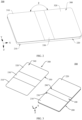
- FIG. 1 is a schematic diagram of a structure of a foldable electronic device 500 in a folded state according to an embodiment of this application.
- FIG. 2 is a schematic diagram of a structure of a foldable electronic device 500 in a flattened state according to an embodiment of this application.
- a width direction of the foldable electronic device 500 is defined as an X direction
- a length direction of the foldable electronic device 500 is defined as a Y direction
- a thickness direction of the foldable electronic device 500 is defined as a Z direction.
- the X, Y and Z directions are perpendicular to each other.
- the foldable electronic device 500 includes but is not limited to a mobile phone (cellphone), a notebook computer (notebook computer), a tablet computer (tablet personal computer), a laptop computer (laptop computer), a personal digital assistant (personal digital assistant), a wearable device (wearable device), or a vehicle-mounted device (mobile device).
- a mobile phone cellphone
- notebook computer notebook computer
- tablet computer tablet personal computer
- laptop computer laptop computer
- personal digital assistant personal digital assistant
- wearable device wearable device
- vehicle-mounted device mobile device
- the foldable electronic device 500 shown in FIG. 1 is in a folded state and the foldable electronic device 500 shown in FIG. 2 is in a flattened state.
- an unfolding angle ⁇ of the foldable electronic device 500 shown in FIG. 2 is 180 degrees means that ⁇ may be 180 degrees, or may be approximately 180 degrees, for example, 170 degrees, 175 degrees, 185 degrees, or 190 degrees. Angles used as examples for description in the following can be understood identically.
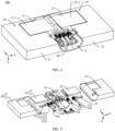
- FIG. 3 is a schematic diagram of a partial exploded structure of the foldable electronic device 500 shown in FIG. 2 .
- the foldable electronic device 500 includes a folding apparatus 200 and a display screen 300, and the display screen 300 is mounted on the folding apparatus 200.
- the display screen 300 includes a display surface 340 and a mounting surface 350, and the display surface 340 and the mounting surface 350 are disposed opposite to each other.
- the display surface 340 is configured to display a text, an image, a video, and the like.
- the display screen 300 includes a first portion 310, a second portion 320, and a foldable portion 330.
- the foldable portion 330 is located between the first portion 310 and the second portion 320, and may be bent in the Y direction.
- the first portion 310, the second portion 320, and the foldable portion 330 jointly constitute the display screen 300.
- the display screen 300 is a flexible display, for example, an organic light-emitting diode (organic light-emitting diode, OLED) display, an active-matrix organic light-emitting diode (active-matrix organic light-emitting diode, AMOLED) display, a mini light-emitting diode (mini organic light-emitting diode) display, a micro light-emitting diode (micro organic light-emitting diode) display, a micro organic light-emitting diode (micro organic light-emitting diode) display, or a quantum dot light-emitting diode (quantum dot light emitting diodes, QLED) display.
- OLED organic light-emitting diode
- AMOLED active-matrix organic light-emitting diode
- mini light-emitting diode mini organic light-emitting diode
- micro light-emitting diode micro organic light-emit
- the folding apparatus 200 includes a first housing 210, a second housing 220, and a rotating mechanism 100.
- the first housing 210 is provided with a first mounting groove 230
- the second housing 220 is provided with a second mounting groove 240
- the first mounting groove 230 communicates with the second mounting groove 240 to form a mounting groove.
- the rotating mechanism 100 is mounted in the mounting groove and is invariably connected to the first housing 210 and the second housing 220, so that the first housing 210 and the second housing 220 are rotatably connected to each other.
- the display screen 300 is mounted on the folding apparatus 200 and the mounting surface 350 is invariably connected to the folding apparatus 200.
- the first housing 210 bears the first portion 310 of the display screen 300
- the second housing 220 bears the second portion 320.
- the first portion 310 is mounted on the first housing 210
- the second portion 320 is mounted on the second housing 220.
- the rotating mechanism 100 and the foldable portion 330 are disposed opposite to each other.
- the first housing 210 and the second housing 220 may be rotated relative to each other by using the rotating mechanism 100, so that the folding apparatus 200 switches between a folded state and a flattened state.
- the first housing 210 and the second housing 220 are rotated relative to each other by using the rotating mechanism 100, and the first housing 210 and the second housing 220 are relatively close to each other to drive the display screen 300 to fold, so that the foldable electronic device 500 is folded.
- the foldable electronic device 500 is in a folded state, the foldable portion 330 of the display screen 300 is bent, and the first portion 310 and the second portion 320 are disposed opposite to each other.
- the display screen 300 is located between the first housing 210 and the second housing 220. This can greatly reduce a probability of damaging the display screen 300, and effectively protect the display screen 300.
- the first housing 210 and the second housing 220 are relatively far away from each other to drive the display screen 300 to further unfold, until the foldable electronic device 500 is unfolded.
- the folding apparatus 200 is in a flattened state, an included angle between the first housing 210 and the second housing 220 is ⁇ , the foldable portion 330 is unfolded, and the first portion 310 and the second portion 320 are relatively unfolded.
- included angles between the first portion 310, the second portion 320, and the foldable portion 330 are all ⁇ , and the display screen 300 has a display region with a large area. This implements large-screen display of the foldable electronic device 500, thereby improving use experience of a user.
- ⁇ is 180 degrees. In other embodiments, ⁇ may be alternatively approximately 180 degrees, for example, may be 170 degrees, 175 degrees, 185 degrees, or 190 degrees.
- FIG. 4 is a schematic diagram of a partial structure of a rotating mechanism 100 in the foldable electronic device 500 shown in FIG. 3 .
- FIG. 5 is a schematic diagram of an exploded structure of the rotating mechanism 100 shown in FIG. 4 .
- FIG. 4 and FIG. 5 show only a partial structure of the rotating mechanism 100 in a positive direction of a Y axis.
- the fastening plate 20, the main swing arm 30, and the synchronization assembly 40 are a group of substructures.
- the entire rotating mechanism 100 has at least two groups of the foregoing substructures, and the fastening base 10 is provided with one group of the foregoing substructures at each of two opposite ends in the Y direction.
- one end of the fastening base 10 is provided with a fastening plate 20, a main swing arm 30, and a synchronization assembly 40, and the other end of the fastening base 10 is also provided with a fastening plate 20, a main swing arm 30, and a synchronization assembly 40.
- one group of the foregoing substructures is added between the substructures at the two ends of the fastening base 10, and the substructures are located in the middle of the fastening base 10.
- two groups of the foregoing substructures may be alternatively added between the substructures at the two ends of the fastening base 10.
- a quantity of the substructures may be adjusted depending on an actual situation.
- fastening plates 20 and bases 10 in two groups of the foregoing substructures may be integrally formed.
- the main swing arms 30 and the synchronization assemblies 40 in the two groups of the foregoing substructures are connected to one fastening plate 20 and share one base 10.
- the fastening plate 20 includes a first fastening plate 21 and a second fastening plate 22.
- the main swing arm 30 includes a first main swing arm 31 and a second main swing arm 32.
- the first main swing arm 31 and the first fastening plate 21 are mounted on one side of the fastening base 10, and the second main swing arm 32 and the second fastening plate 22 are mounted on the other side of the fastening base 10.
- One end of the first main swing arm 31 is rotatably and slidably connected to the fastening base 10, and the other end of the first main swing arm 31 is invariably connected to the first fastening plate 21.
- FIG. 6 is a schematic diagram of a partial structure of a fastening base 10 in the rotating mechanism 100 shown in FIG. 5 .
- the fastening base 10 is elongated, and the length direction of the fastening base 10 is parallel to the Y direction.
- the fastening base 10 includes a bottom plate 11, a first side plate 12, a second side plate 13, a first end plate 14, and a second end plate (not shown in the figure).
- the first side plate 12 and the second side plate 13 are disposed opposite to each other, and the first side plate 12 and the second side plate 13 are respectively connected to two opposite sides of the bottom plate 11 in the X direction.
- the first end plate 14 and the second end plate are opposite to each other, and the first end plate 14 and the second end plate are both connected between the first side plate 12 and the second side plate 13 and are respectively connected to two opposite sides of the bottom plate 11 in the Y direction.
- first side plate 12 and the second side plate 13 are both arc-shaped, and the first side plate 12 and the second side plate 13 are bent in a direction in which the first side plate 12 and the second side plate 13 are close to each other.
- the first side plate 12 further includes a first side plate notch 121, and the first side plate notch 121 is disposed at an edge of the first side plate 12.
- the second side plate 13 further includes a second side plate notch 131, and the second side plate notch 131 is disposed at an edge of the second side plate 13.
- the first side plate notch 121 and the second side plate notch 131 are opposite to each other.
- the bottom plate 11 is provided with a first rotating groove 111 and a second rotating groove 112. Bottom walls of the first rotating groove 111 and the second rotating groove 112 are both arc-shaped, and extension directions of the bottom walls of the first rotating groove 111 and the second rotating groove 112 are both parallel to the X direction.
- the first rotating groove 111 and the second rotating groove 112 are opposite to each other, and are spaced and are disposed opposite to each other in the Y direction.
- the first rotating groove 111 and the second rotating groove 112 are configured to mount the main swing arm 30, and the main swing arm 30 can slide and rotate in the first rotating groove 111 and the second rotating groove 112.
- the fastening base 10 is further provided with an accommodation groove 113.
- the accommodation groove 113 is enclosed by the bottom plate 11, the first side plate 12, and the second side plate 13.
- the accommodation groove 113 is spaced from the first rotating groove 111 and the second rotating groove 112.
- the accommodation groove 113 is configured to mount the synchronization assembly 40.
- FIG. 6 shows only a partial structure of the fastening base 10 in the positive direction of the Y axis, and a structure of the fastening base 10 in a negative direction of the Y axis and the structure of the fastening base 10 in the positive direction of the Y axis are an axisymmetric structure or a centrosymmetric structure.
- FIG. 7 is schematic diagrams of structures of a first fastening plate 21 and a second fastening plate 22 in the rotating mechanism 100 shown in FIG. 5 .
- the fastening plate 20 includes the first fastening plate 21 and the second fastening plate 22.
- the first fastening plate 21 is of a rectangular plate-like structure.
- the first fastening plate 21 includes a first surface 211, a second surface 212, a first side surface 213, and a second side surface 214.
- the first side surface 213 and the second side surface 214 are disposed opposite to each other, and both the first side surface 213 and the second side surface 214 are parallel to the Y direction.
- the first side surface 213 is an arc surface, and is configured to fit in with the first side plate 12 of the fastening base 10.
- the first surface 211 and the second surface 212 are disposed opposite to each other. Both the first surface 211 and the second surface 212 are connected between the first side surface 213 and the second side surface 214.
- the first fastening plate 21 is provided with a first groove 215 and a first sliding slot 216.
- the first groove 215 is disposed by being recessed from the first surface 211 and penetrates through the first side surface 213. It can be understood that a groove with an arc-shaped interface is formed at a junction of the first surface 211 and the first side surface 213, the groove recesses the first fastening plate 21, and a length direction of the first groove 215 is the Y direction.
- the first groove 215 is configured to mount the main swing arm 30, so that the main swing arm 30 is invariably connected to the first fastening plate 21.
- the first sliding slot 216 is spaced from the first groove 215 and a length extension direction of the first sliding slot 216 is parallel to the X direction.
- An opening of the first sliding slot 216 is located at a groove bottom wall of the first groove 215 and the first surface 211.
- the first sliding slot 216 is configured to mount the synchronization assembly 40, so that the synchronization assembly 40 is slidably connected to the first fastening plate 21.
- a structure of the second fastening plate 22 is the same as that of the first fastening plate 21.
- the second fastening plate 22 includes a third surface 221, a fourth surface 222, a third side surface 223, and a fourth side surface 224.
- the third side surface 223 and the fourth side surface 224 are disposed opposite to each other, and both are parallel to the Y direction.
- the third side surface 223 is an arc surface, and is configured to fit in with the second side plate 13 of the fastening base 10.
- the third surface 221 and the fourth surface 222 are disposed opposite to each other.
- the second fastening plate 22 is provided with a second groove 225 and a second sliding slot 226.
- a structure of the second groove 225 is the same as that of the first groove 215, and a structure of the second sliding slot 226 is the same as that of the first sliding slot 216.
- the second groove 225 is configured to mount the main swing arm 30, so that the main swing arm 30 is invariably connected to the second fastening plate 22.
- An opening of the second sliding slot 226 is located at a groove bottom wall of the second groove 225 and the third surface 221.
- the second sliding slot 226 is configured to mount the synchronization assembly 40, so that the synchronization assembly 40 is slidably connected to the second fastening plate 22.
- FIG. 8 is schematic diagrams of enlarged structures of a first main swing arm 31 and a second main swing arm 32 in the rotating mechanism 100 shown in FIG. 5 .
- the first main swing arm 31 includes a first swing body 311 and a first rotating body 312.
- the first swing body 311 is of a rectangular plate-like structure.
- the first swing body 311 includes a first upper surface 3111, a first lower surface 3112, a first side face 3113, and a second side face 3114.
- the first upper surface 3111 and the first lower surface 3112 are both perpendicular to the Z direction, and the first upper surface 3111 and the first lower surface 3112 are disposed opposite to each other.
- the first upper surface 3111 is a plane.
- the first side face 3113 and the second side face 3114 are both parallel to the Y direction, the first side face 3113 and the second side face 3114 are disposed opposite to each other, and the first side face 3113 and the second side face 3114 are both connected between the first upper surface 3111 and the first lower surface 3112.
- the first rotating body 312 includes a first rotating surface 3121, the first rotating surface 3121 is arc-shaped, a bending direction of the first rotating surface 3121 faces the first upper surface 3111, and a bending radian of the first rotating surface 3121 is consistent with a bending radian of the bottom wall of the first rotating groove 111.
- a bending radian of the first rotating surface 3121 may be roughly the same as a bending radian of the bottom wall of the first rotating groove 111.
- the first rotating body 312 further includes a first free end 3122 and a first connecting end (not shown in the figure), and the first free end 3122 and the first connecting end are respectively located at two opposite ends in an extension direction of the first rotating surface 3121.
- the first connecting end is invariably connected to the first lower surface 3112, and the first free end 3122 is located on one side of the first side face 3113 and has a same orientation as the first upper surface 3111.
- the second main swing arm 32 includes a second swing body 321 and a second rotating body 322.
- a structure of the second swing body 321 is the same as that of the first swing body 311.
- the second swing body 321 includes a second upper surface 3211, a second lower surface 3212, a third side face 3213, and a fourth side face 3214.
- a structure of the second rotating body 322 is the same as that of the first rotating body 312.
- the second rotating body 322 includes a second rotating surface 3221, a second free end 3222, and a second connecting end.
- a structure of the second rotating surface 3221 is the same as that of the first rotating surface 3121, and a bending radian of the second rotating surface 3221 is consistent with or is roughly the same as a bending radian of the bottom wall of the second rotating groove 112.
- the second connecting end is invariably connected to the second lower surface 3212, the second free end 3222 extends from the third side face 3213 towards a direction away from the second rotating body 322, and a bending direction of the second rotating surface 3221 faces the second upper surface 3211.
- a location of the second rotating body 322 is corresponding to a location of the second rotating groove 112.
- the first fastening plate 21 and the first main swing arm 31 are located on one side of the fastening base 10 in the X direction, and the second fastening plate 22 and the second main swing arm 32 are located on the other side of the fastening base 10 in the X direction.
- the first sliding slot 216 is in relative communication with the first side plate notch 121, the first rotating body 312 of the first main swing arm 31 is located in the first rotating groove 111, the first rotating surface 3121 is in contact with the bottom wall of the first rotating groove 111, and the first rotating body 312 can slide and rotate in the first rotating groove 111.
- the first swing body 311 is mounted in the first groove 215 and is invariably connected to an inner wall of the first groove 215.
- the first fastening plate 21 is invariably connected to the first housing 210.
- the second sliding slot 226 is in relative communication with the second side plate notch 131, the second rotating body 322 of the second main swing arm 32 is located in the second rotating groove 112, the second rotating surface 3221 is in contact with the bottom wall of the second rotating groove 112, and the second rotating body 322 can slide and rotate in the second rotating groove 112.
- the second swing body 321 is mounted in the second groove 225 and is invariably connected to an inner wall of the second groove 225.
- the second fastening plate 22 is invariably connected to the second housing 220.
- the first main swing arm 31 and the second main swing arm 32 may be alternatively disposed opposite to each other side by side in the X direction. In other embodiments, the first main swing arm 31 and the second main swing arm 32 are disposed in a staggered manner in the Y direction.
- Rotation of the first housing 210 relative to the fastening base 10 can drive the first fastening plate 21 to rotate relative to the fastening base 10, to drive the first main swing arm 31 to rotate relative to the fastening base 10, and enable the first rotating body 312 to rotate and slide in the first rotating groove 111.
- Rotation of the second housing 220 relative to the fastening base 10 can drive the second fastening plate 22 to rotate relative to the fastening base 10, to drive the second main swing arm 32 to rotate relative to the fastening base 10, and enable the second rotating body 322 to rotate and slide in the second rotating groove 112.
- Rotation directions of the first fastening plate 21 and the second fastening plate 22 are opposite, and rotation directions of the first main swing arm 31 and the second main swing arm 32 are opposite.
- the rotating mechanism 100 switches from a flattened state to a folded state
- the first fastening plate 21 and the first main swing arm 31 are rotated counterclockwise by ⁇ 1
- the second fastening plate 22 and the second main swing arm 32 are rotated clockwise by ⁇ 2.
- the rotating mechanism 100 switches from a folded state to a flattened state
- the first fastening plate 21 and the first main swing arm 31 are rotated clockwise by ⁇ 2
- the second fastening plate 22 and the second main swing arm 32 are rotated counterclockwise by ⁇ 1.
- the first fastening plate 21 and the second fastening plate 22 rotate in a direction in which the first fastening plate 21 and the second fastening plate 22 are close to each other, the first fastening plate 21 drives the first main swing arm 31 to rotate counterclockwise by ⁇ 1, and the first rotating body 312 is rotated counterclockwise by ⁇ 1 in the first rotating groove 111; and the second fastening plate 22 drives the second main swing arm 32 to rotate clockwise by ⁇ 2, and the second rotating body 322 is rotated clockwise by ⁇ 2 in the second rotating groove 112, so that the rotating mechanism 100 is in the folded state.
- the first fastening plate 21 and the second fastening plate 22 rotate in a direction in which the first fastening plate 21 and the second fastening plate 22 are away from each other, the first fastening plate 21 drives the first main swing arm 31 to rotate clockwise by ⁇ 2, and the first rotating body 312 is rotated clockwise by ⁇ 2 in the first rotating groove 111; and the second fastening plate 22 drives the second main swing arm 32 to rotate counterclockwise by ⁇ 1, and the second rotating body 322 is rotated counterclockwise by ⁇ 1 in the second rotating groove 112, so that the rotating mechanism 100 is restored to the flattened state.
- the first fastening plate 21 and the second fastening plate 22 are unfolded relative to the fastening base 10, and the first main swing arm 31 and the second main swing arm 32 are unfolded relative to the fastening base 10.
- the first upper surface 3111, the first surface 211, the second upper surface 3211, and the second surface 212 are approximately in a same plane, and jointly support the display screen 300, to ensure stability of the display screen 300 and enable the display screen 300 to perform display normally.
- first fastening plate 21 and the second fastening plate 22 are disposed, the first fastening plate 21 is invariably connected to the first housing 210, and the second fastening plate 22 is invariably connected to the second housing 220, so that connection strength between the fastening plate 20 and the housings can be increased, and rotation stability of the foldable electronic device 500 is improved.
- first main swing arm 31 and the second main swing arm 32 are disposed, so that the first fastening plate 21 and the second fastening plate 22 are rotated relative to the fastening base 10, to increase rotation stability of the rotating mechanism 100.
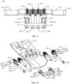
- FIG. 9 is a schematic diagram of a structure of a synchronization assembly 40 in the rotating mechanism 100 shown in FIG. 4 .
- FIG. 10 is schematic diagrams of exploded structures of a fastening base and the synchronization assembly 40 that is shown in FIG. 9 .
- the synchronization assembly 40 includes a first synchronization swing arm 41, a second synchronization swing arm 42, a synchronization gear 43, connecting shafts, and a damping member 44.
- the synchronization gear 43 is mounted on the fastening base 10 through the connecting shafts, the first synchronization swing arm 41 and the second synchronization swing arm 42 are respectively connected to two opposite sides of the synchronization gear 43 in the X direction, the first synchronization swing arm 41 is slidably connected to the first fastening plate 21, and the second synchronization swing arm 42 is slidably connected to the second fastening plate 22.
- the damping member 44 is mounted on the fastening base 10, is located on a side face of the synchronization gear 43, and is invariably connected to the synchronization gear 43.
- the synchronization gear 43 includes a first gear 431, intermediate gears, and a second gear 432.
- the intermediate gears include a third gear 433 and a fourth gear 434. All of the first gear 431, the second gear 432, the third gear 433, and the fourth gear 434 are of hollow structures.
- the first gear 431 is provided with a first through hole 4311, and the first through hole 4311 penetrates through the first gear 431 in an axial direction.
- the second gear 432 is provided with a second through hole 4321, and the second through hole 4321 penetrates through the second gear 432 in an axial direction.
- the third gear 433 is provided with a third through hole 4331, and the third through hole 4331 penetrates through the third gear 433 in an axial direction.
- the fourth gear 434 is provided with a fourth through hole 4341, and the fourth through hole 4341 penetrates through the fourth gear 434 in an axial direction.
- the connecting shafts include a first connecting shaft 444, a second connecting shaft 445, a third connecting shaft 446, and a fourth connecting shaft 447.
- the first gear 431, the third gear 433, the fourth gear 434, and the second gear 432 are sequentially disposed side by side, and two adjacent gears are engaged with each other.
- the first gear 431, the second gear 432, the third gear 433, and the fourth gear 434 are sequentially sleeved on the first connecting shaft 444, the second connecting shaft 445, the third connecting shaft 446, and the fourth connecting shaft 447.
- Rotation directions of the first gear 431 and the fourth gear 434 are the same, rotation directions of the third gear 433 and the second gear 432 are the same, and rotation directions of the first gear 431 and the second gear 432 are opposite.
- the synchronization gear 43 is mounted in the accommodation groove 113 of the fastening base 10, and an axial direction of the synchronization gear 43 is parallel to the Y direction.
- FIG. 11 is a partial schematic exploded diagram of a synchronization assembly 40 according to an embodiment of this application.
- the first gear 431 may include a plurality of first protrusions 4312, and each first protrusion 4312 includes a first inclined surface 4312a, a second inclined surface 4312b, a fifth side face 4312c, a sixth side face 4312d, and a first plane 4312e.
- the first inclined surface 4312a and the second inclined surface 4312b are respectively connected to two opposite sides of the first plane 4312e, and the first inclined surface 4312a and the second inclined surface 4312b are disposed opposite to each other.
- the fifth side face 4312c is connected to the first inclined surface 4312a and the first plane 4312e
- the sixth side face 4312d is connected to the second inclined surface 4312b and the first plane 4312e.
- the fifth side face 4312c and the sixth side face 4312d are disposed opposite to each other, and the fifth side face 4312c and the sixth side face 4312d may be parallel to the axial direction of the first gear 431. Included angles between the fifth side face 4312c and the first plane 4312e and between the sixth side face 4312d and the first plane 4312e may be right angles, that is, the sixth side face 4312d and the fifth side face 4312c are perpendicular to the first plane 4312e.
- the plurality of first protrusions 4312 are all invariably connected to a side face of the first gear 431, and the plurality of first protrusions 4312 are arranged at intervals in a circumferential direction at a periphery of the first through hole 4311.
- the first gear 431 is further provided with first recess portions 4313.
- One first recess portion 4313 is disposed between two adjacent first protrusions 4312. In other words, the plurality of first protrusions 4312 and the plurality of first recess portions 4313 are alternately arranged in the circumferential direction at the periphery of the first through hole 4311.
- the second gear 432 may include a plurality of second protrusions 4322, and a structure of the second protrusion 4322 is the same as that of the first protrusion 4312.
- the plurality of second protrusions 4322 are all invariably connected to a side face of the second gear 432, and the plurality of second protrusions 4322 are arranged at intervals in a circumferential direction at a periphery of the second through hole 4321.
- the second gear 432 is further provided with second recess portions 4323.
- One second recess portion 4323 is disposed between two adjacent second protrusions 4322, and a structure of the second recess portion 4323 is the same as that of the first recess portion 4313.
- the plurality of second protrusions 4322 and the plurality of second recess portions 4323 are alternately arranged in the circumferential direction at the periphery of the second through hole 4321.
- the second protrusions 4322 and the first protrusions 4312 are located on a same side of the synchronization gear 43.
- the first synchronization swing arm 41 includes a first end 411 and a second end 412, and the first end 411 and the second end 412 are disposed opposite to each other.
- the first end 411 of the first synchronization swing arm 41 is invariably connected to the first gear 431, and the second end 412 is configured to slidably connect to the first fastening plate 21.
- the second synchronization swing arm 42 includes a third end 421 and a fourth end 422, and the third end 421 and the fourth end 422 are disposed opposite to each other.
- the third end 421 of the second synchronization swing arm 42 is invariably connected to the second gear 432, and the fourth end 422 is configured to slidably connect to the second fastening plate 22.
- FIG. 12 is a schematic diagram of a partial structure of a damping body according to this application.
- the damping member 44 includes a baffle plate 441, connecting seats, and a damping body 45.
- the connecting seats include a first connecting seat 442 and a second connecting seat 443.
- One end of the first damping body 451 is connected to the first connecting seat 442, and the other end of the first damping body 451 is connected to the baffle plate 441.
- One end of the second damping body 452 is connected to the second connecting seat 443, and the other end of the second damping body 452 is connected to the baffle plate 441.
- the baffle plate 441 is of an elongated plate-like structure.
- the baffle plate 441 includes a first face 441a and a second face 441b.
- the first face 441a and the second face 441b are disposed opposite to each other.
- the baffle plate 441 is provided with a first mounting hole 4411, a second mounting hole 4412, a third mounting hole 4413, and a fourth mounting hole 4414.
- the first mounting hole 4411, the second mounting hole 4412, the third mounting hole 4413, and the fourth mounting hole 4414 are disposed at intervals along a length direction of the baffle plate 441, and penetrate through the first face 441a and the second face 441b.
- the first connecting seat 442 is of a cylindrical structure, and includes a third face 442a and a fourth face 442b disposed opposite to each other.
- the first connecting seat 442 is provided with a fifth mounting hole 4421, and the fifth mounting hole 4421 penetrates through the third face 442a and the fourth face 442b.
- the second connecting seat 443 is also of a cylindrical structure, and includes a fifth face 443a and a sixth face 443b disposed opposite to each other.
- the second connecting seat 443 is provided with a sixth mounting hole 4431, and the sixth mounting hole 4431 penetrates through the fifth face 443a and the sixth face 443b.
- the fourth face 442b of the first connecting seat 442 is configured to connect to the first gear 431, the fifth mounting hole 4421 and the first mounting hole 4411 are opposite to each other, the first connecting shaft 444 can pass through the fifth mounting hole 4421 and the first mounting hole 4411, and the first damping body 451 is located on a side of an outer shaft of the first connecting shaft 444.
- the sixth face 443b of the second connecting seat 443 is configured to connect to the second gear 432, the sixth mounting hole 4431 and the fourth mounting hole 4414 are opposite to each other, the second connecting shaft 445 can pass through the sixth mounting hole 4431 and the fourth mounting hole 4414, and the second damping body 452 is located on a side of an outer shaft of the second connecting shaft 445.
- the first connecting seat 442 further includes a plurality of third protrusions 4422, and the plurality of protrusions are disposed on the third face 442a of the first connecting seat 442.
- Each third protrusion 4422 includes a seventh side face 4422a and an eighth side face 4422b disposed opposite to each other, and a third inclined surface 4422c and a fourth inclined surface 4422d disposed opposite to each other.
- the seventh side face 4422a and the eighth side face 4422b may be connected perpendicularly to the third face 442a of the first connecting seat 442, and the seventh side face 4422a and the eighth side face 4422b may be parallel to an axial direction of the first connecting seat 442.
- the third inclined surface 4422c is connected to the seventh side face 4422a and the fourth inclined surface 4422d, an included angle between the third inclined surface 4422c and the seventh side face 4422a is an obtuse angle, and the third inclined surface 4422c and the fourth inclined surface 4422d are disposed at an included angle.
- the fourth inclined surface 4422d is connected to the third inclined surface 4422c and the eighth side face 4422b, and an included angle between the fourth inclined surface 4422d and a fourth plane is an obtuse angle.
- the plurality of third protrusions 4422 are all invariably connected to the third face 442a of the first connecting seat 442 and the plurality of first protrusions 4312 are arranged at intervals in a circumferential direction at a periphery of the fifth mounting hole 4421.
- One third recess portion 4423 is disposed between two adjacent third protrusions 4422.
- the plurality of third protrusions 4422 and the plurality of third recess portions 4423 are alternately arranged in the circumferential direction at a periphery of the first connecting seat 442.
- the second connecting seat 443 has a same structure as the first connecting seat 442 and includes a plurality of fourth protrusions 4432, and a structure of the fourth protrusion 4432 is the same as that of the third protrusion 4422.
- the plurality of fourth protrusions 4432 are all connected to the fifth face 443a of the second connecting seat 443, and the plurality of fourth protrusions 4432 are arranged at intervals at a periphery of the sixth mounting hole 4431.
- the fourth protrusions 4432 and the third protrusions 4422 are located on a same side of the connecting seats.
- the second connecting seat 443 further includes fourth recess portions 4433.
- a structure of the fourth recess portion 4433 is the same as that of the third recess portion 4423.
- the plurality of fourth protrusions 4432 and the plurality of fourth recess portions 4433 are alternately arranged at a periphery of the second connecting seat 443.
- the first damping body 451 may include a plurality of strip-shaped bodies, and is specifically made of a strip-shaped memory alloy material.
- the first damping body 451 includes four strip-shaped bodies, one end of the four strip-shaped bodies is connected to a periphery of the first mounting hole 4411 of the second face 441b of the baffle plate 441, and the other end of the four strip-shaped bodies is connected to the periphery of the fifth mounting hole 4421 of the third face 442a of the first connecting seat 442.
- the four strip-shaped bodies are evenly distributed in an axial direction of the first mounting hole 4411 and the fifth mounting hole 4421.
- the second damping body 452 may include a plurality of strip-shaped bodies, and is specifically made of a strip-shaped memory alloy material.
- the second damping body 452 includes four strip-shaped bodies, one end of the four strip-shaped bodies is connected to a periphery of the fourth mounting hole 4414 of the second face 441b of the baffle plate 441, and the other end of the four strip-shaped bodies is connected to the periphery of the sixth mounting hole 4431 of the fifth face 443a of the second connecting seat 443.
- the four strip-shaped bodies are evenly distributed in an axial direction of the fourth mounting hole 4414 and the sixth mounting hole 4431.
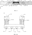
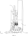
- FIG. 13 is a schematic diagram of a cross-section of the rotating mechanism 100 shown in FIG. 4 .
- the synchronization assembly 40 is mounted on the fastening base 10.
- the synchronization gear 43 and the damping member 44 are arranged in the fastening base 10 along the Y direction.
- the first synchronization swing arm 41 and the second synchronization swing arm 42 are respectively located on two opposite sides of the fastening base 10 in the X direction.
- a part that is of the first synchronization swing arm 41 and that is provided with the second end 412 extends into the first sliding slot 216 of the first fastening plate 21, and is slidably and rotatably connected to the first fastening plate 21.
- a part that is of the second synchronization swing arm 42 and that is provided with the fourth end 422 extends into the second sliding slot 226 of the second fastening plate 22, and is slidably and rotatably connected to the second fastening plate 22.
- the first connecting shaft 444, the second connecting shaft 445, the third connecting shaft 446, and the fourth connecting shaft 447 are all mounted on the fastening base 10. Length directions of the four connecting shafts are all parallel to the Y direction, and the four connecting shafts are disposed in parallel at intervals along the Y direction. End portions of the four connecting shafts are all invariably connected to the fastening base 10.
- the first connecting shaft 444 sequentially passes through the first gear 431, the first connecting seat 442, and the damping body 45. Specifically, the first connecting shaft 444 passes through the first through hole 4311, the fifth mounting hole 4421, the first damping body 451, and the first mounting hole 4411, and is invariably connected to the baffle plate 441.
- the first gear 431, the first connecting seat 442, and the first damping body 451 may be rotated relative to the first connecting shaft 444.
- the second connecting shaft 445 sequentially passes through the second gear 432, the second connecting seat 443, and the damping member 44. Specifically, the second connecting shaft 445 passes through the second through hole 4321, the sixth mounting hole 4431, the second damping body 452, and the fourth mounting hole 4414, and is invariably connected to the baffle plate 441.
- the second gear 432, the second connecting seat 443, and the second damping body 452 may be rotated relative to the second connecting shaft 445.
- the other end of the third connecting shaft 446 sequentially passes through the third through hole 4331 and the second mounting hole 4412, and is invariably connected to the baffle plate 441.
- the third gear may be rotated relative to the third connecting shaft 446.
- the other end of the fourth connecting shaft 447 sequentially passes through the fourth through hole 4341 and the fourth mounting hole 4414, and is invariably connected to the baffle plate 441.
- the fourth gear 434, the second connecting seat 443, and the second damping body 452 may be rotated relative to the fourth connecting shaft 447.
- the first synchronization swing arm 41 When the first fastening plate 21 is rotated relative to the fastening base 10, the first synchronization swing arm 41 is driven to rotate, and the first synchronization swing arm 41 slides and rotates in the first sliding slot 216.
- the first gear 431 is driven to synchronously rotate
- the second gear 432 is driven to rotate through the third gear 433 and the fourth gear 434
- the second synchronization swing arm 42 is driven to rotate
- the second fastening plate 22 is driven to rotate
- the second synchronization swing arm 42 slides and rotates in the second sliding slot 226.
- the first synchronization swing arm 41 and the second synchronization swing arm 42 are synchronously rotated, and the first fastening plate 21 and the second fastening plate 22 are synchronously rotated.
- the first connecting seat 442 is driven to rotate.
- the first connecting seat 442 is rotated, one end that is of the first damping body 451 and that is connected to the first connecting seat 442 is driven to rotate, so that the first damping body 451 is deformed and generates damping force, thereby implementing damping effect.
- the rotation of the first gear 431 can drive the fourth gear 434 to rotate, to drive the second connecting seat 443 to rotate in an opposite direction to the first connecting seat 442.
- the first gear 431 is invariably connected to the first connecting seat 442
- the first connecting seat 442 is sleeved on the first connecting shaft 444
- the first protrusions 4312 are connected to the third recess portions 4423
- the third protrusions 4422 are connected to the first recess portions 4313.
- shapes of the first protrusions 4312 match shapes of the third recess portions 4423
- the first protrusions 4312 can be exactly clamped to the third recess portions 4423
- the third protrusions 4422 can be exactly clamped to the first recess portions 4313.
- a fifth side face 4312c of a first protrusion 4312 is butted with a seventh side face 4422a of one third protrusion 4422
- a first inclined surface 4312a is butted with a third inclined surface 4422c
- a sixth side face 4312d and a second inclined surface 4312b are respectively butted with an eighth side face 4422b and a fourth inclined surface 4422d of another third protrusion 4422.
- the second gear 432 is invariably connected to the second connecting seat 443 in a same manner as the manner in which the first gear 431 is connected to the first connecting seat 442.
- the second protrusions 4322 are connected to the fourth recess portions 4433 and are adjacent to the fourth protrusions 4432, and the fourth protrusions 4432 are connected to the second recess portions 4323.
- shapes of the second protrusions 4322 match shapes of the fourth recess portions 4433, the second protrusions 4322 can be exactly clamped to the fourth recess portions 4433, and likewise the fourth protrusions 4432 can be exactly clamped to the second recess portions 4323.
- the first synchronization swing arm 41 and the second synchronization swing arm 42 are respectively mounted on the two opposite sides of the fastening base in the width direction and are rotatably connected to the fastening base 10.
- One end of the damping body 45 is connected to the first synchronization swing arm 41, the other end of the damping body 45 is connected to the baffle plate 441, two opposite ends of the damping body 45 are disposed along the length direction of the fastening base 10, and the damping body 45 is made of a shape memory alloy.
- the first synchronization swing arm 41 is rotated relative to the fastening base 10 to drive one end of the damping body 45 to rotate, the first synchronization swing arm 41 and the second synchronization swing arm 42 are relatively unfolded from the folded state, and the damping body 45 is in a second state, where the second state is that the damping body 45 is deformed and generates damping force relative to the first synchronization swing arm 41.
- first synchronization swing arm 41 and the second synchronization swing arm 42 can be rotated relative to each other under the action of external force exerted on the rotating mechanism.
- first synchronization swing arm 41 When the first synchronization swing arm 41 is rotated, one end of the damping body 45 is driven to rotate relative to the fastening base 10.
- One end that is of the damping body 45 and that is connected to the baffle plate 441 remains stationary relative to the fastening base 10.
- the damping body 45 is deformed when the first synchronization swing arm 41 is rotated. Because the damping body 45 is made of a shape memory alloy, the damping body 45 can generate damping force during deformation.
- the damping body 45 When the damping body 45 is in the first state, the first synchronization swing arm 41 and the second synchronization swing arm 42 are relatively folded, and the rotating mechanism is in a folded state. In a process in which the rotating mechanism is relatively unfolded from the folded state, the first synchronization swing arm 41 is rotated to exert external force on the damping body 45, the damping body 45 is deformed from the first state to the second state, and the damping body 45 generates damping force resisting the external force during deformation under stress, to provide damping hand feeling.
- the shape memory alloy is used as the damping body 45 of the terminal mechanism to implement hovering of the foldable electronic device at a folding angle, a flattening angle, or another unfolding angle, thereby improving use experience of the user.
- a structure and an assembly method of the rotating mechanism 100 can be further simplified, so that precision of the product is improved and costs of the terminal product are decreased.
- FIG. 14A is a schematic diagram of a structure of the damping member 44 shown in FIG. 12 with the damping body 45 in a first state (an initial state).
- FIG. 14B is a schematic diagram of a structure of the damping member 44 shown in FIG. 12 with the damping body 45 in a second state.
- FIG. 14C is a schematic diagram of a structure of the damping member 44 shown in FIG. 12 with the damping body 45 in a third state.
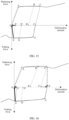
- FIG. 15 is a line graph showing a relationship between deformation and external force in a first embodiment of the damping body 45 according to an embodiment of this application.
- the damping body 45 includes a plurality of independent strip-shaped bodies made of a shape memory alloy. As shown in FIG. 14A , in this embodiment, the damping body 45 is in the first state. The first state of the damping body 45 is the initial state, the damping body 45 is in a stable shape, and the stable shape in the first state may be a stable shape obtained through training. It should be understood that the damping body 45 is made of a shape memory alloy material, and a microstructure of the shape memory alloy in the first state may be austenite or a combination of austenite and martensite. In this embodiment, the damping body 45 is in the first state, and the rotating mechanism 100 is in a folded state. As shown in FIG. 15 , a point O is a deformation amount when the rotating mechanism 100 is in a folded state and the damping body 45 is in the first state (the deformation amount in this embodiment is 0).
- That the rotating mechanism 100 is in a folded state means that the first fastening plate 21 and the second fastening plate 22 are rotated relative to the base 10 and are close to each other.
- the damping body 45 and the folded state of the rotating mechanism 100 it can also be understood that if the rotating mechanism 100 is in a folded state, the corresponding damping body 45 is in a natural state. In this case, the damping body can keep the first synchronization swing arm 41 and the second synchronization swing arm 42 in a folded state.
- the rotating mechanism 100 is in a folded state, the foldable electronic apparatus having the rotating mechanism 100 is in a folded state.
- the damping body 45 in FIG 14B is in the second state. Deformation occurs and specific damping force is generated in the second state, so that the rotating mechanism 100 is unfolded from the folded state when being exerted by external force. Specifically, the damping body 45 first undergoes elastic deformation under the action of external force, that is, the strip-shaped bodies undergo elastic deformation. With continuous external force, the deformation amount of the damping body 45 continuously increases. When the external force reaches a specific value, the damping body 45 reaches a yield stress, namely, a point A in FIG. 15 . With continuous external force, the damping body 45 undergoes inelastic deformation and is located between points A and B in FIG. 15 , that is, reaches the second state.
- the damping body has damping force.
- shapes of the strip-shaped bodies are twisted in this case, that is, the damping body 45 is twisted along an outer edge of a circumferential surface of the first connecting shaft 444, and deformation amounts of the plurality of strip-shaped bodies are the same or approximately the same.
- the damping body 45 is deformed and the microstructure can also change, and the austenite in the first state can change to martensite.
- the rotating mechanism 100 is unfolded from the folded state, and the first synchronization swing arm 41 and the second synchronization swing arm 42 are relatively unfolded at an angle that may be greater than an angle at which the rotating mechanism 100 is in a folded state and less than an angle at which the rotating mechanism 100 is in a flattened state (the flattened state means a fully flattened state).
- the damping body 45 is in the second state; and assuming that the rotating mechanism 100 is unfolded to 90 degrees (a tolerance range is allowed), an angle between the first fastening plate 21 and the second fastening plate 22 is 90 degrees.
- the damping force of the damping body 45 enables the rotating mechanism 100 (between the first synchronization swing arm 41 and the second synchronization swing arm 42, and also between the first fastening plate 21 and the second fastening plate 22) to have damping hand feel and hovering (the first fastening plate 21 and the second fastening plate 22 are positioned at an angle of 90 degrees between each other) performance, so that the electronic device using the rotating mechanism has damping hand feel and hovering performance.
- the deformation amount of the damping body 45 slightly decreases, and then the damping body 45 keeps in a stable shape.
- the shape of the damping body 45 does not change any longer, and the corresponding rotating mechanism 100 remains in a stable hovering state.
- the first fastening plate 21 and the second fastening plate 22 relatively stop, and an angle between the first fastening plate 21 and the second fastening plate 22 in this case is less than 90 degrees (including a tolerance range).
- An angle of the rotating mechanism 100 may be fastened, to implement hovering of the rotating mechanism 100 (the foldable electronic device 500) at any angle at which the rotating mechanism 100 is not fully unfolded.
- the damping body 45 when the angle between the first fastening plate 21 and the second fastening plate 22 are slightly rotated (a range larger than a tolerance) by more than 90 degrees under the action of external force, the damping body 45 is deformed to reach the point B. If the external force is removed, the deformation amount of the damping body 45 slightly decreases to the point B', and then the damping body 45 keeps in a stable shape.
- the angle between the first fastening plate 21 and the second fastening plate 22 in this case may be 90 degrees.
- the damping body 45 in FIG 14C is in the third state.
- the rotating mechanism 100 is in a fully flattened state, that is, is fully unfolded, and the damping body 45 is in the third state.
- the deformation amounts of the strip-shaped bodies of the damping body 45 are maximum.
- the deformation amount of the damping body 45 is a point C shown in FIG. 15 .
- the damping body 45 in this case has a maximum deformation amount and maximum damping force. If the external force is removed in this case, the deformation amount of the damping body 45 slightly decreases, to reach a point C' shown in FIG. 15 .
- the rotating mechanism remains in a stable hovering state, that is, the rotating mechanism is in a general flattened state.
- the first fastening plate 21 and the second fastening plate 22 are unfolded at an angle of approximately 180 degrees relative to the base 10, and a specific range of the unfolding angle may be between 160 degrees and 180 degrees.
- a process in which the second state changes to the third state is a process in which the deformation amount of the damping body increases and the damping force increases. In this process, the damping force always exists, and effect of providing damping hand feeling is achieved. In other words, a function of continuously providing damping hand feeling is achieved, and hovering can be implemented at any angle.
- the deformation amount of the damping body 45 changes from a deformed state (the third state) shown in FIG. 14C to the initial state (the first state) shown in FIG. 14A .
- the damping body 45 is deformed when being exerted by external force.
- the deformation amount of the damping body 45 decreases from the unfolded state to the folded state.
- the deformation amount of the damping body 45 slightly increases and then keeps stable, and the rotating mechanism 100 remains in a stable hovering state in this case.
- the shape of the damping body 45 after the external force is removed tends to be restored to the shape when no external force is exerted.
- the deformation amount of the damping body 45 continues to decrease. As shown at a point E in FIG. 15 , the rotating mechanism 100 is actually in a general folded state in this case. If the external force is removed, in this case, the deformation amount of the shape memory alloy slightly increases, the damping body 45 is in a second intermediate state, and the rotating mechanism 100 is slightly unfolded and then hovers. As shown at a point E' in FIG. 15 , a difference in deformation amounts between the point E and the point E' is equal to an angle at which the rotating mechanism 100 is slightly unfolded.
- the rotating mechanism 100 includes a general folded state and a fully folded state (which may also be referred to as folded states) (but a tolerance range is allowed for both states); and the rotating mechanism 100 includes a general flattened state and a fully flattened state (which may also be referred to as flattened states) (but a tolerance range is allowed for both states).
- the point E indicates that the rotating mechanism 100 is in a general folded state, and in this case, it indicates that the foldable electronic device 500 is close to a state in which a folding action is completed.
- the point E to the point E' in FIG. 15 indicate that when external force is removed at the point E, the strip-shaped bodies have residual stresses. After the residual stresses are released, the deformation amount of the damping body slightly increases and then keeps stable.
- the point E' indicates the deformation amount of the damping body 45 in this case, and the strip-shaped bodies have a slight deformation amount in this case.
- a second preset temperature is applied to the strip-shaped bodies, to enable the strip-shaped bodies to be restored to the initial state, that is, the point O in the figure.
- the second preset temperature is a temperature applied when a stable shape is trained for the shape memory alloy.
- stable shapes of the strip-shaped bodies of the damping body 45 are the initial state.
- the strip-shaped bodies of the damping body 45 can be restored to the initial state and keep in stable shapes under the action of the second preset temperature, so that the rotating mechanism 100 can be in a fully folded state and keep in a folded state, and the damping body 45 is restored to the state in FIG. 14A .
- external force may be exerted on the foldable electronic device 500, until the foldable electronic device 500 reaches a folded state.
- the rotating mechanism 100 is in a fully folded state when the external force is not removed, and a second preset temperature is applied to the shape memory alloy in this case.
- the shape memory alloy can be restored to the initial state and keep in a stable shape under the action of the second preset temperature, so that the foldable electronic device 500 keeps in a stable folded state.
- FIG. 16 is a line graph showing a relationship between deformation and external force in the second embodiment of the damping body 45 according to an embodiment of this application.
- the damping body 45 may have two stable shapes.
- the damping body 45 appears in a stable shape macroscopically.
- a first stable shape is the foregoing initial state (the first state)
- a second stable shape is the foregoing shape of the damping body 45 when the rotating mechanism 100 is in the flattened state (the third state).
- the damping body 45 In the third state, the damping body 45 is in a maximum deformed state, and the damping body 45 in this state is in another stable shape obtained through training.
- the damping body 45 is made of a shape memory alloy material, and the microstructure of the shape memory alloy without phase transformation may be austenite, or both austenite and martensite exist in the microstructure. The austenite portion in the microstructure of the damping body 45 may be transformed into martensite when the damping member 44 changes from the first state to the third state.
- the deformation amounts of the strip-shaped bodies of the damping body 45 are maximum, and the deformation amount of the damping body 45 is a point C shown in FIG. 16 . If the external force is removed in this case, the deformation amount of the damping body 45 slightly decreases. In this case, the damping body 45 is in a first intermediate state, that is, reaches a point C' shown in FIG. 16 , and the rotating mechanism 100 remains in a stable hovering state, that is, the rotating mechanism 100 is in a general flattened state.
- the first fastening plate 21 and the second fastening plate 22 are unfolded at an angle of approximately 180 degrees relative to the base 10, and a specific range of the unfolding angle may be between 160 degrees and 180 degrees.
- a difference from the first embodiment lies in that, in this embodiment, as shown from the point C' to a point X' in FIG. 16 , when the external force is removed at the point C, the strip-shaped bodies of the damping body 45 have residual stresses. After the residual stresses are released, the deformation amounts of the strip-shaped bodies of the damping body 45 slightly decrease and then keep stable.
- the point C' indicates the deformation amount of the damping body 45 in this case, and the strip-shaped bodies of the damping body 45 have wrinkles in this case. Then, a first preset temperature is applied to the strip-shaped bodies, to enable the strip-shaped bodies to be restored to the third state and reach the point X' (fully flattened).
- the first preset temperature is a temperature applied when a stable shape (the damping body 45 is in the third state in this case) is trained for the shape memory alloy.
- the damping body 45 can be restored to the third state and keep in a stable shape under the action of the first preset temperature, so that the rotating mechanism 100 can keep in a fully flattened state stably.
- external force may be exerted on the rotating mechanism 100, until the rotating mechanism 100 reaches a flattened state.
- the point C indicates the deformation amount of the damping body 45 under the external force.
- the rotating mechanism 100 is in a fully folded state when the external force is not removed, and a first preset temperature is applied to the strip-shaped bodies.
- the strip-shaped bodies can be restored to the third state and keep in stable shapes without external force under the action of the first preset temperature.
- the point X' in FIG. 16 indicates the deformation amount of the damping body 45 when the rotating mechanism 100 is fully flattened without external force.
- the microstructure of the strip-shaped bodies to which the second preset temperature is applied can undergo phase transformation from austenite (the initial state) into martensite (the third state).
- austenite the initial state
- martensite the third state
- the strip-shaped bodies without external force are not deformed, but keep in stable shapes, to ensure stable hovering of the rotating mechanism 100 in the flattened state.
- a difference from the first embodiment lies in that the damping body 45 includes at least one strip-shaped body made of a super-elastic shape memory alloy.
- the damping body 45 has four strip-shaped bodies.
- the damping body 45 has one stable shape, that is, the super-elastic shape memory alloy has one stable shape in shape training, and a training temperature corresponding to this stable shape is less than a room temperature.
- FIG. 17 is a line graph showing a relationship between deformation and external force in a third embodiment of the damping body 45 according to an embodiment of this application. When the rotating mechanism 100 is exerted by external force, refer to a point H in FIG. 17 .
- the strip-shaped bodies undergo elastic deformation.
- stresses of the strip-shaped bodies exceed an elastic limit. Even if the stresses do not increase any longer, the super-elastic shape memory alloy begins to undergo obvious inelastic deformation.
- the super-elastic shape memory alloy is restored to a stable shape in this case, that is, the trained stable shape of the super-elastic shape memory alloy. In this case, the rotating mechanism 100 is restored to the folded state.
- the super-elastic shape memory alloy is deformed and generates damping force, to provide damping hand feeling for the user.
- the rotating mechanism 100 or the foldable electronic device 500 using the rotating mechanism 100 is flattened, the rotating mechanism 100 or the rotating mechanism 100 is fastened by a locking member, so that the rotating mechanism 100 can keep in a stable flattened state. If the locking member of the rotating mechanism 100 is released, when no external force is exerted, a deformation amount of the super-elastic shape memory alloy can decrease, and the super-elastic shape memory alloy can be restored to the stable shape in the folded state, so that the rotating mechanism 100 or the foldable electronic device 500 using the rotating mechanism 100 is automatically folded.
- the locking member is disposed in the first housing 210 and the second housing 220, or on the first fastening plate 21 and the second fastening plate 22 or the base 10 of the rotating mechanism 100.
- the locking member may be a magnet, and is used for fastening and locking by magnetic attraction.
- the locking member can be a buckle apparatus, and is used for clamping and fastening.
- phase transformation for example, may undergo phase transformation into a parent phase (austenite) or a sub-phase (martensite)
- a macroscopic shape of the shape memory alloy changes.
- a damping mechanism (the damping body 45) of a terminal structure having properties in various states can be formed through training by using the shape memory alloy.
- Mechanical force needed by phase transformation or deformation of the shape memory alloy is used as damping force of the folding mechanism, to provide damping hand feeling for the user and implement multi-steady and multi-angle hovering of the foldable electronic device 500.
- mechanical force generated by a folding action or an unfolding action of the user can drive the shape memory alloy to undergo phase transformation or deformation and follow memorized shapes.
- the shape memory alloy can be designed or trained to produce a variety of folding steady-state through temperature adjustment or exertion of external force.
- the damping body 45 may be provided with corresponding steady-state phases (for example, the first state, the second state, and the third state in the foregoing embodiments) in the states when included angles between the first synchronization swing arm 41 and the second synchronization swing arm 42 are 0°, 45°, 90°, 135°, and 180°, so that the rotating mechanism 100 can hover at corresponding angles.
- FIG. 18 is a schematic diagram of a partial structure of the rotating mechanism 100 shown in FIG. 4 in a folded state.
- the first fastening plate 21 and the second fastening plate 22 are relatively folded, the first main swing arm 31 and the second main swing arm 32 are relatively folded, and the first synchronization swing arm 41 and the second synchronization swing arm 42 are relatively folded.
- the damping body 45 of the damping member is in the initial state (the first state).
- the damping member positions the rotating mechanism 100 to the folded state, that is, the rotating mechanism 100 hovers in the folded state.
- the first fastening plate 21 and the second fastening plate 22 relatively hover at a specific angle
- the first main swing arm 31 and the second main swing arm 32 relatively hover at a specific angle
- the first synchronization swing arm 41 and the second synchronization swing arm 42 relatively hover at a specific angle.
- the foldable electronic device 500 using the shown rotating mechanism 100 in the folded state is also in a folded state.
- the first housing and the second housing are relatively folded, and the display screen is folded, that is, the electronic device is in the folded state.
- the screen of the electronic device in a folded state is inoperable and protected.
- FIG. 19 is a schematic diagram of a partial structure of the rotating mechanism 100 shown in FIG. 4 in an intermediate state between a folded state and a flattened state.
- the first fastening plate 21 When the rotating mechanism 100 is in an unfolded state from the folded state, the first fastening plate 21 is rotated counterclockwise by ⁇ 1, to drive the first main swing arm 31 to rotate counterclockwise by ⁇ 1, and the first rotating body 312 slides in the first rotating groove 111 in a direction away from the fastening base 10.
- the first fastening plate 21 is rotated counterclockwise by ⁇ 1, to further drive the first synchronization swing arm 41 to rotate counterclockwise by ⁇ 1, and the first synchronization swing arm 41 slides in the first sliding slot 216.
- the first gear 431 When the first synchronization swing arm 41 is rotated counterclockwise by ⁇ 1, the first gear 431 is driven to rotate counterclockwise by ⁇ 1, to drive the first connecting seat 442 to rotate counterclockwise by ⁇ 1.
- the first gear 431 When the first gear 431 is rotated counterclockwise by ⁇ 1, the third gear 433 and the fourth gear 434 are further driven to rotate, to drive the second gear 432 to rotate clockwise by ⁇ 2.
- the first gear 431 further drives the first connecting seat 442 to rotate counterclockwise by co1.
- the first connecting seat 442 drives one end of the first damping body 451 to rotate counterclockwise by ⁇ 1, and the baffle plate 441 does not move, so that the first damping body 451 is deformed (the second state). As shown in FIG. 14B and FIG. 15 , the first damping body 451 is deformed and generates damping force.
- the second gear 432 further drives the second connecting seat 443 to rotate clockwise by ⁇ 2, to enable one end of the second damping body 452 to rotate clockwise by ⁇ 2, so that the second damping body 452 is deformed and generates damping force (the second state).
- the damping force generated by the first damping body 451 and the second damping body 452 through deformation provides damping hand feel for the rotating mechanism 100, to provide damping hand feel for the foldable electronic device 500.
- the first damping body 451 and the second damping body 452 enable the rotating mechanism 100 to hover at a specific angle as described in the foregoing embodiments, even if the foldable electronic device 500 is folded.
- FIG. 20 is a schematic diagram of a partial structure of the rotating mechanism 100 shown in FIG. 4 in a flattened state.
- the first fastening plate 21 continues to be rotated counterclockwise by ⁇ 1, to drive the first main swing arm 31 to continue to rotate counterclockwise by ⁇ 1, and the first rotating body 312 continues to slide in the first rotating groove 111 in the direction away from the fastening base 10.
- the first fastening plate 21 is rotated counterclockwise by ⁇ 1; and the first synchronization swing arm 41 drives the first gear 431 to continue to rotate counterclockwise by ⁇ 1, and drives the second gear 432, the second synchronization swing arm 42, and the second fastening plate 22 to rotate clockwise by ⁇ 2.
- the first connecting seat 442 is driven to continue to rotate, and the first connecting seat 442 drives the first damping body 451 to be further deformed until the rotating mechanism 100 is folded.
- the second gear 432 is rotated clockwise by ⁇ 2, to further drive the second synchronization swing arm 42 to rotate clockwise by ⁇ 2, and drive the second fastening plate 22 to rotate clockwise by ⁇ 2; and the second synchronization swing arm 42 slides in the second sliding slot 226, so that the rotating mechanism 100 is rotated to a folded state.
- the second gear 432 also drives the second connecting seat 443 to rotate, and the second connecting seat 443 drives the second damping body 452 to be further deformed until the rotating mechanism 100 is folded.
- the first damping body 451 and the second damping body 452 are deformed (the third state), and deformation of the first damping body 451 and the second damping body 452 can provide damping hand feeling for the rotating mechanism 100, thereby improving use experience of the user.
- the flattened rotating mechanism 100 is folded again.
- the external force is removed after the damping body 45 is flattened, and the deformation amount slightly decreases and then keeps stable. Therefore, the damping body 45 in the first embodiment is deformed starting from a shape with a deformation amount slightly less than that in the third state, until the damping body 45 changes to the first state shown in FIG. 14A .
- the rotating mechanism 100 completes the folding action under the action of external force, and the first synchronization swing arm 41 and the second synchronization swing arm 42 are relatively close to each other until the rotating mechanism 100 is fully folded.
- the rotating mechanism 100 is in a flattened state from the folded state, and correspondingly the damping body is in the third state.
- a second preset temperature may be applied to the damping body 45.
- the second preset temperature may cause the damping body 45 to undergo phase transformation (from austenite in the folded state to martensite in the flattened state), and the phase transformation of the damping body 45 enables the shape of the damping body 45 to change (from the first state of the damping body 45 shown in FIG. 14A to the third state shown in FIG. 14C ).
- the third state of the damping body 45 can keep stable when the rotating mechanism 100 is in the flattened state.
- the rotating mechanism 100 in the second embodiment changes from a flattened state to a folded state under the action of external force, the first synchronization swing arm 41 and the second synchronization swing arm 42 start to be relatively folded from a relatively unfolded state, and the damping member 44 in the second embodiment provides damping force for the first synchronization swing arm 41 and the second synchronization swing arm 42 in this process.
- the damping body 45 in the second embodiment is folded from the fully flattened state of the rotating mechanism 100, that is, restored to the first state from the third state of the damping body 45. Changes in the deformation amount and the damping force of the damping body 45 are shown in FIG. 15 , and are not described again.
- damping hand feel of the rotating mechanism 100 can be understood as damping force exerted on the first synchronization swing arm 41 and the second synchronization swing arm 42 during rotation, that is, acting force exerted by the damping member 44 on the synchronization gear 43.
- the damping body 45 is disposed, so that damping force exerted on the synchronization assembly 40 during rotation is resistance generated during elastic deformation or inelastic deformation of the damping body 45.
- the elastic deformation of the damping body 45 occurs before the yield stress of the damping body 45, and the inelastic deformation of the damping body occurs after the yield stress of the damping body 45.
- a quantity of damping bodies 45 can be reduced, so that the structure of the rotating mechanism 100 can be simplified, and the assembly difficulty, weight, and costs of the rotating mechanism 100 can be reduced.
- it is conducive to reducing a volume of the rotating mechanism 100, to implement thinning and lightness of the foldable electronic device 500.
- the damping body 45 of the damping member 44 is in the maximum deformed state (the third state).
- the damping member 44 in the first embodiment is slightly deformed from the shape in the third state and then keeps stable.
- the damping member 44 in the second embodiment keeps in the shape in the third state and positions the rotating mechanism 100 to the flattened state, that is, the rotating mechanism 100 hovers in the flattened state.
- the locking member fastens the rotating mechanism 100 to the flattened state
- the damping member 44 is in the maximum deformed state (the third state)
- the damping member 44 has elastic force in this case.
- the elastic force of the damping member 44 enables the rotating mechanism 100 to be automatically folded from the flattened state after the locking member is released.
- the first gear 431 may be rotated relative to the first connecting shaft 444
- the first connecting seat 442 may be rotated relative to the first connecting shaft 444 to drive one end of the first damping body 451 to rotate relative to the first connecting shaft 444
- both the baffle plate 441 and one end that is of the first damping body 451 and that is connected to the baffle plate 441 remain stationary relative to the first connecting shaft 444.
- the other end of the second connecting shaft 445 sequentially passes through the third through hole 4331 and the second mounting hole 4412, and is invariably connected to the baffle plate 441.
- the third gear may be rotated relative to the second connecting shaft 445, and the baffle plate 441 is stationary relative to the second connecting shaft 445.
- the other end of the third connecting shaft 446 sequentially passes through the fourth through hole 4341 and the third mounting hole 4413, and is invariably connected to the baffle plate 441.
- the fourth gear 434 may be rotated relative to the third connecting shaft 446, and the baffle plate 441 may be stationary relative to the third connecting shaft 446.
- the other end of the fourth connecting shaft 447 sequentially passes through the second through hole 4321, the sixth mounting hole 4431, the second damping body 452, and the fourth mounting hole 4414, and is invariably connected to the baffle plate 441.
- the second gear 432 may be rotated relative to the fourth connecting shaft 447, and the baffle plate 441 and one end that is of a fourth damping body 45 and that is connected to the baffle plate 441 may be stationary relative to the fourth connecting shaft 447.
- a connecting shaft may be rotated relative to the baffle plate 441 and the fastening base 10, that is, the connecting shaft may be rotated along an axis of the connecting shaft. It is understood that rotation of the connecting shaft does not affect a folding action or an unfolding action of the foldable electronic device 500. Therefore, whether the connecting shaft is rotated is not limited herein.
- a damping body 45 is sleeved at a periphery of a connecting shaft, so that the connecting shaft fastens the corresponding damping body 45. This can prevent any damping body 45 from deviating from a Y-axis direction.
Landscapes
- Engineering & Computer Science (AREA)
- General Engineering & Computer Science (AREA)
- Computer Hardware Design (AREA)
- Theoretical Computer Science (AREA)
- Mechanical Engineering (AREA)
- Physics & Mathematics (AREA)
- Human Computer Interaction (AREA)
- General Physics & Mathematics (AREA)
- Signal Processing (AREA)
- Mathematical Physics (AREA)
- Microelectronics & Electronic Packaging (AREA)
- Telephone Set Structure (AREA)
Applications Claiming Priority (2)
| Application Number | Priority Date | Filing Date | Title |
|---|---|---|---|
| CN202210565212.9A CN117145855B (zh) | 2022-05-23 | 2022-05-23 | 转动机构和可折叠电子设备 |
| PCT/CN2023/092305 WO2023226715A1 (fr) | 2022-05-23 | 2023-05-05 | Mécanisme rotatif et dispositif électronique pliable |
Publications (3)
| Publication Number | Publication Date |
|---|---|
| EP4403785A1 true EP4403785A1 (fr) | 2024-07-24 |
| EP4403785A4 EP4403785A4 (fr) | 2025-02-26 |
| EP4403785B1 EP4403785B1 (fr) | 2025-09-10 |
Family
ID=88885450
Family Applications (1)
| Application Number | Title | Priority Date | Filing Date |
|---|---|---|---|
| EP23810788.2A Active EP4403785B1 (fr) | 2022-05-23 | 2023-05-05 | Mécanisme rotatif et dispositif électronique pliable |
Country Status (4)
| Country | Link |
|---|---|
| US (1) | US12541231B2 (fr) |
| EP (1) | EP4403785B1 (fr) |
| CN (1) | CN117145855B (fr) |
| WO (1) | WO2023226715A1 (fr) |
Family Cites Families (30)
| Publication number | Priority date | Publication date | Assignee | Title |
|---|---|---|---|---|
| JP3718776B2 (ja) * | 2003-02-12 | 2005-11-24 | インターナショナル・ビジネス・マシーンズ・コーポレーション | 情報処理装置及び回転制御装置 |
| TW201324091A (zh) * | 2011-12-06 | 2013-06-16 | Compal Electronics Inc | 樞轉機構及可折疊電子裝置 |
| CN105805151B (zh) * | 2014-12-30 | 2018-11-06 | 深圳超多维科技有限公司 | 阻尼铰链机构及折叠式电子设备 |
| CN205847346U (zh) * | 2016-06-07 | 2016-12-28 | 杭州安费诺飞凤通信部品有限公司 | 一种柔性屏移动终端的铰链、铰链装置及柔性屏移动终端 |
| DE202018101276U1 (de) | 2018-03-07 | 2018-04-03 | frenzel + mayer solutions GbR (vertretungsberechtiger Gesellschafter: Philip Frenzel, 73430 Aalen, DE) | Umhausung für ein elektronisches Gerät |
| US10677307B2 (en) * | 2018-04-24 | 2020-06-09 | Microsoft Technology Licensing, Llc | Barrel spring |
| CN208445595U (zh) * | 2018-06-06 | 2019-01-29 | Oppo(重庆)智能科技有限公司 | 电子设备 |
| JP7149780B2 (ja) * | 2018-09-14 | 2022-10-07 | 日本電産サンキョー株式会社 | 開閉装置 |
| US10534407B2 (en) * | 2018-09-25 | 2020-01-14 | Intel Corporation | On-demand torque engagement mechanism for second display adjustability |
| CN111615277B (zh) * | 2019-02-25 | 2021-11-05 | Oppo广东移动通信有限公司 | 转动装置、壳体及电子装置 |
| CN114519960B (zh) * | 2019-02-25 | 2024-04-02 | Oppo广东移动通信有限公司 | 转动装置、壳体及电子装置 |
| US10851571B2 (en) * | 2019-04-02 | 2020-12-01 | Dell Products L.P. | Hinge assembly with adjustable torque |
| CN210830134U (zh) * | 2019-06-27 | 2020-06-23 | 华为技术有限公司 | 折叠模组及折叠式电子设备 |
| CN113366927A (zh) | 2019-07-15 | 2021-09-07 | 深圳市柔宇科技股份有限公司 | 折叠装置及电子设备 |
| US20210064096A1 (en) * | 2019-08-28 | 2021-03-04 | Intel Corporation | Infinite Holding Pivot Mechanisms for Dual Screen Systems |
| KR102798666B1 (ko) | 2019-12-13 | 2025-04-18 | 후아웨이 테크놀러지 컴퍼니 리미티드 | 회전축 구조체 및 전자 장치 |
| CN114063706B (zh) * | 2020-07-29 | 2025-05-20 | 华为技术有限公司 | 阻尼机构、折叠铰链与可折叠电子设备 |
| CN112995368B (zh) * | 2019-12-13 | 2021-12-21 | 华为技术有限公司 | 一种铰链和移动终端 |
| CN110985524B (zh) * | 2019-12-20 | 2024-09-06 | 深圳市长盈精密技术股份有限公司 | 阻尼机构、折叠显示装置及通讯设备 |
| CN111131568B (zh) | 2019-12-23 | 2021-07-16 | 华为技术有限公司 | 电子设备 |
| CN113282136B (zh) * | 2020-02-20 | 2024-01-30 | 北京小米移动软件有限公司 | 铰链结构和折叠式电子设备 |
| CN111609029B (zh) * | 2020-05-22 | 2021-05-04 | 深圳市柔宇科技有限公司 | 一种折叠装置及柔性电子设备 |
| US11353933B2 (en) * | 2020-05-27 | 2022-06-07 | Apple Inc. | Self-actuating hinge mechanism for electronic device |
| CN113805646B (zh) | 2020-06-15 | 2024-01-30 | 华为技术有限公司 | 折叠装置及电子设备 |
| CN114060398A (zh) | 2020-08-07 | 2022-02-18 | 华为技术有限公司 | 铰链机构及折叠屏设备 |
| CN112178041A (zh) * | 2020-09-16 | 2021-01-05 | 珠海格力电器股份有限公司 | 一种阻尼机构、折叠铰链及电子装置 |
| CN113923279B (zh) * | 2021-01-14 | 2022-11-29 | 荣耀终端有限公司 | 折叠组件及可折叠电子设备 |
| CN113067924B (zh) | 2021-03-19 | 2023-05-23 | 维沃移动通信有限公司 | 折叠机构、支架结构和电子设备 |
| CN113404766B (zh) * | 2021-07-02 | 2024-12-31 | 江苏精研科技股份有限公司 | 一种用于折叠屏的铰链机构以及移动终端 |
| CN113864324B (zh) * | 2021-09-27 | 2022-10-18 | 维沃移动通信有限公司 | 折叠组件和电子设备 |
-
2022
- 2022-05-23 CN CN202210565212.9A patent/CN117145855B/zh active Active
-
2023
- 2023-05-05 WO PCT/CN2023/092305 patent/WO2023226715A1/fr not_active Ceased
- 2023-05-05 EP EP23810788.2A patent/EP4403785B1/fr active Active
- 2023-05-05 US US18/704,277 patent/US12541231B2/en active Active
Also Published As
| Publication number | Publication date |
|---|---|
| CN117145855A (zh) | 2023-12-01 |
| US20240419220A1 (en) | 2024-12-19 |
| EP4403785B1 (fr) | 2025-09-10 |
| US12541231B2 (en) | 2026-02-03 |
| WO2023226715A1 (fr) | 2023-11-30 |
| CN117145855B (zh) | 2024-08-02 |
| EP4403785A4 (fr) | 2025-02-26 |
Similar Documents
| Publication | Publication Date | Title |
|---|---|---|
| US11336759B2 (en) | Rotating shaft mechanism and mobile terminal | |
| CN217682778U (zh) | 转动机构和可折叠电子设备 | |
| KR102611811B1 (ko) | 힌지 기구 및 폴더블 이동 단말기 | |
| CN115388085B (zh) | 电子设备和折叠装置 | |
| EP3842647A1 (fr) | Mécanisme d'arbre rotatif et terminal mobile | |
| JP7765657B2 (ja) | ヒンジ機構および折り畳み式デバイス | |
| CN213458799U (zh) | 折叠机构及终端设备 | |
| WO2021197289A1 (fr) | Mécanisme de pliage et dispositif électronique | |
| EP4207716B1 (fr) | Appareil pliable et dispositif électronique | |
| EP4239987B1 (fr) | Mécanisme d'arbre de rotation et terminal mobile pliable | |
| EP4279755A1 (fr) | Mécanisme rotatif et dispositif électronique pliable | |
| EP4583083A1 (fr) | Mécanisme rotatif et dispositif électronique pliable | |
| EP4417826A1 (fr) | Mécanisme d'arbre rotatif et appareil électronique | |
| CN218863071U (zh) | 一种转轴机构、支撑装置和折叠屏电子设备 | |
| EP4403785A1 (fr) | Mécanisme rotatif et dispositif électronique pliable | |
| CN116950983B (zh) | 转动机构和可折叠电子设备 | |
| EP4269825B1 (fr) | Ensemble de pliage et dispositif électronique | |
| CN116838702B (zh) | 转动机构和可折叠电子设备 | |
| CN220910219U (zh) | 一种弹簧、阻尼组件和电子设备 | |
| CN116928199B (zh) | 转动机构和可折叠电子设备 | |
| CN217784008U (zh) | 转动机构及电子设备 | |
| EP4561033A1 (fr) | Appareil électronique et ensemble de pliage | |
| WO2024060876A1 (fr) | Mécanisme de synchronisation et dispositif électronique | |
| CN119755188A (zh) | 铰链组件和电子设备 | |
| CN119855997A (zh) | 转动机构和可折叠电子设备 |
Legal Events
| Date | Code | Title | Description |
|---|---|---|---|
| STAA | Information on the status of an ep patent application or granted ep patent |
Free format text: STATUS: THE INTERNATIONAL PUBLICATION HAS BEEN MADE |
|
| PUAI | Public reference made under article 153(3) epc to a published international application that has entered the european phase |
Free format text: ORIGINAL CODE: 0009012 |
|
| STAA | Information on the status of an ep patent application or granted ep patent |
Free format text: STATUS: REQUEST FOR EXAMINATION WAS MADE |
|
| 17P | Request for examination filed |
Effective date: 20240419 |
|
| AK | Designated contracting states |
Kind code of ref document: A1 Designated state(s): AL AT BE BG CH CY CZ DE DK EE ES FI FR GB GR HR HU IE IS IT LI LT LU LV MC ME MK MT NL NO PL PT RO RS SE SI SK SM TR |
|
| A4 | Supplementary search report drawn up and despatched |
Effective date: 20250128 |
|
| RIC1 | Information provided on ipc code assigned before grant |
Ipc: G06F 1/16 20060101ALI20250122BHEP Ipc: H04M 1/02 20060101ALI20250122BHEP Ipc: H05K 5/02 20060101ALI20250122BHEP Ipc: F16C 11/10 20060101ALI20250122BHEP Ipc: F16C 11/04 20060101AFI20250122BHEP |
|
| GRAP | Despatch of communication of intention to grant a patent |
Free format text: ORIGINAL CODE: EPIDOSNIGR1 |
|
| STAA | Information on the status of an ep patent application or granted ep patent |
Free format text: STATUS: GRANT OF PATENT IS INTENDED |
|
| DAV | Request for validation of the european patent (deleted) | ||
| DAX | Request for extension of the european patent (deleted) | ||
| INTG | Intention to grant announced |
Effective date: 20250408 |
|
| GRAS | Grant fee paid |
Free format text: ORIGINAL CODE: EPIDOSNIGR3 |
|
| GRAA | (expected) grant |
Free format text: ORIGINAL CODE: 0009210 |
|
| STAA | Information on the status of an ep patent application or granted ep patent |
Free format text: STATUS: THE PATENT HAS BEEN GRANTED |
|
| AK | Designated contracting states |
Kind code of ref document: B1 Designated state(s): AL AT BE BG CH CY CZ DE DK EE ES FI FR GB GR HR HU IE IS IT LI LT LU LV MC ME MK MT NL NO PL PT RO RS SE SI SK SM TR |
|
| REG | Reference to a national code |
Ref country code: GB Ref legal event code: FG4D |
|
| REG | Reference to a national code |
Ref country code: CH Ref legal event code: EP |
|
| REG | Reference to a national code |
Ref country code: DE Ref legal event code: R096 Ref document number: 602023006632 Country of ref document: DE |
|
| REG | Reference to a national code |
Ref country code: IE Ref legal event code: FG4D |
|
| REG | Reference to a national code |
Ref country code: NL Ref legal event code: FP |
|
| PG25 | Lapsed in a contracting state [announced via postgrant information from national office to epo] |
Ref country code: NO Free format text: LAPSE BECAUSE OF FAILURE TO SUBMIT A TRANSLATION OF THE DESCRIPTION OR TO PAY THE FEE WITHIN THE PRESCRIBED TIME-LIMIT Effective date: 20251210 |
|
| REG | Reference to a national code |
Ref country code: LT Ref legal event code: MG9D |
|
| PG25 | Lapsed in a contracting state [announced via postgrant information from national office to epo] |
Ref country code: FI Free format text: LAPSE BECAUSE OF FAILURE TO SUBMIT A TRANSLATION OF THE DESCRIPTION OR TO PAY THE FEE WITHIN THE PRESCRIBED TIME-LIMIT Effective date: 20250910 |
|
| PG25 | Lapsed in a contracting state [announced via postgrant information from national office to epo] |
Ref country code: HR Free format text: LAPSE BECAUSE OF FAILURE TO SUBMIT A TRANSLATION OF THE DESCRIPTION OR TO PAY THE FEE WITHIN THE PRESCRIBED TIME-LIMIT Effective date: 20250910 |
|
| PG25 | Lapsed in a contracting state [announced via postgrant information from national office to epo] |
Ref country code: GR Free format text: LAPSE BECAUSE OF FAILURE TO SUBMIT A TRANSLATION OF THE DESCRIPTION OR TO PAY THE FEE WITHIN THE PRESCRIBED TIME-LIMIT Effective date: 20251211 |
|
| PG25 | Lapsed in a contracting state [announced via postgrant information from national office to epo] |
Ref country code: SE Free format text: LAPSE BECAUSE OF FAILURE TO SUBMIT A TRANSLATION OF THE DESCRIPTION OR TO PAY THE FEE WITHIN THE PRESCRIBED TIME-LIMIT Effective date: 20250910 |
|
| PG25 | Lapsed in a contracting state [announced via postgrant information from national office to epo] |
Ref country code: LV Free format text: LAPSE BECAUSE OF FAILURE TO SUBMIT A TRANSLATION OF THE DESCRIPTION OR TO PAY THE FEE WITHIN THE PRESCRIBED TIME-LIMIT Effective date: 20250910 |
|
| PG25 | Lapsed in a contracting state [announced via postgrant information from national office to epo] |
Ref country code: PL Free format text: LAPSE BECAUSE OF FAILURE TO SUBMIT A TRANSLATION OF THE DESCRIPTION OR TO PAY THE FEE WITHIN THE PRESCRIBED TIME-LIMIT Effective date: 20250910 Ref country code: BG Free format text: LAPSE BECAUSE OF FAILURE TO SUBMIT A TRANSLATION OF THE DESCRIPTION OR TO PAY THE FEE WITHIN THE PRESCRIBED TIME-LIMIT Effective date: 20250910 |
|
| PG25 | Lapsed in a contracting state [announced via postgrant information from national office to epo] |
Ref country code: RS Free format text: LAPSE BECAUSE OF FAILURE TO SUBMIT A TRANSLATION OF THE DESCRIPTION OR TO PAY THE FEE WITHIN THE PRESCRIBED TIME-LIMIT Effective date: 20251210 |
|
| PG25 | Lapsed in a contracting state [announced via postgrant information from national office to epo] |
Ref country code: ES Free format text: LAPSE BECAUSE OF FAILURE TO SUBMIT A TRANSLATION OF THE DESCRIPTION OR TO PAY THE FEE WITHIN THE PRESCRIBED TIME-LIMIT Effective date: 20250910 |
|
| REG | Reference to a national code |
Ref country code: AT Ref legal event code: MK05 Ref document number: 1836159 Country of ref document: AT Kind code of ref document: T Effective date: 20250910 |
|
| PG25 | Lapsed in a contracting state [announced via postgrant information from national office to epo] |
Ref country code: SM Free format text: LAPSE BECAUSE OF FAILURE TO SUBMIT A TRANSLATION OF THE DESCRIPTION OR TO PAY THE FEE WITHIN THE PRESCRIBED TIME-LIMIT Effective date: 20250910 |
|
| PG25 | Lapsed in a contracting state [announced via postgrant information from national office to epo] |
Ref country code: AT Free format text: LAPSE BECAUSE OF FAILURE TO SUBMIT A TRANSLATION OF THE DESCRIPTION OR TO PAY THE FEE WITHIN THE PRESCRIBED TIME-LIMIT Effective date: 20250910 |
|
| PG25 | Lapsed in a contracting state [announced via postgrant information from national office to epo] |
Ref country code: IT Free format text: LAPSE BECAUSE OF FAILURE TO SUBMIT A TRANSLATION OF THE DESCRIPTION OR TO PAY THE FEE WITHIN THE PRESCRIBED TIME-LIMIT Effective date: 20250910 |
|
| PG25 | Lapsed in a contracting state [announced via postgrant information from national office to epo] |
Ref country code: IS Free format text: LAPSE BECAUSE OF FAILURE TO SUBMIT A TRANSLATION OF THE DESCRIPTION OR TO PAY THE FEE WITHIN THE PRESCRIBED TIME-LIMIT Effective date: 20260110 |
|
| PG25 | Lapsed in a contracting state [announced via postgrant information from national office to epo] |
Ref country code: CZ Free format text: LAPSE BECAUSE OF FAILURE TO SUBMIT A TRANSLATION OF THE DESCRIPTION OR TO PAY THE FEE WITHIN THE PRESCRIBED TIME-LIMIT Effective date: 20250910 Ref country code: PT Free format text: LAPSE BECAUSE OF FAILURE TO SUBMIT A TRANSLATION OF THE DESCRIPTION OR TO PAY THE FEE WITHIN THE PRESCRIBED TIME-LIMIT Effective date: 20260112 |
|
| PG25 | Lapsed in a contracting state [announced via postgrant information from national office to epo] |
Ref country code: EE Free format text: LAPSE BECAUSE OF FAILURE TO SUBMIT A TRANSLATION OF THE DESCRIPTION OR TO PAY THE FEE WITHIN THE PRESCRIBED TIME-LIMIT Effective date: 20250910 Ref country code: SK Free format text: LAPSE BECAUSE OF FAILURE TO SUBMIT A TRANSLATION OF THE DESCRIPTION OR TO PAY THE FEE WITHIN THE PRESCRIBED TIME-LIMIT Effective date: 20250910 |