EP4404072A2 - Bereitstellung einer schnittstelle für ein avionik-datenübertragungssystem - Google Patents
Bereitstellung einer schnittstelle für ein avionik-datenübertragungssystem Download PDFInfo
- Publication number
- EP4404072A2 EP4404072A2 EP24177051.0A EP24177051A EP4404072A2 EP 4404072 A2 EP4404072 A2 EP 4404072A2 EP 24177051 A EP24177051 A EP 24177051A EP 4404072 A2 EP4404072 A2 EP 4404072A2
- Authority
- EP
- European Patent Office
- Prior art keywords
- virtual
- ports
- port
- data transfer
- virtual ports
- Prior art date
- Legal status (The legal status is an assumption and is not a legal conclusion. Google has not performed a legal analysis and makes no representation as to the accuracy of the status listed.)
- Pending
Links
Images


Classifications
-
- G—PHYSICS
- G06—COMPUTING OR CALCULATING; COUNTING
- G06F—ELECTRIC DIGITAL DATA PROCESSING
- G06F13/00—Interconnection of, or transfer of information or other signals between, memories, input/output devices or central processing units
- G06F13/38—Information transfer, e.g. on bus
- G06F13/382—Information transfer, e.g. on bus using universal interface adapter
- G06F13/385—Information transfer, e.g. on bus using universal interface adapter for adaptation of a particular data processing system to different peripheral devices
-
- G—PHYSICS
- G06—COMPUTING OR CALCULATING; COUNTING
- G06F—ELECTRIC DIGITAL DATA PROCESSING
- G06F3/00—Input arrangements for transferring data to be processed into a form capable of being handled by the computer; Output arrangements for transferring data from processing unit to output unit, e.g. interface arrangements
- G06F3/06—Digital input from, or digital output to, record carriers, e.g. RAID, emulated record carriers or networked record carriers
- G06F3/0601—Interfaces specially adapted for storage systems
- G06F3/0602—Interfaces specially adapted for storage systems specifically adapted to achieve a particular effect
- G06F3/0604—Improving or facilitating administration, e.g. storage management
- G06F3/0607—Improving or facilitating administration, e.g. storage management by facilitating the process of upgrading existing storage systems, e.g. for improving compatibility between host and storage device
-
- G—PHYSICS
- G06—COMPUTING OR CALCULATING; COUNTING
- G06F—ELECTRIC DIGITAL DATA PROCESSING
- G06F3/00—Input arrangements for transferring data to be processed into a form capable of being handled by the computer; Output arrangements for transferring data from processing unit to output unit, e.g. interface arrangements
- G06F3/06—Digital input from, or digital output to, record carriers, e.g. RAID, emulated record carriers or networked record carriers
- G06F3/0601—Interfaces specially adapted for storage systems
- G06F3/0628—Interfaces specially adapted for storage systems making use of a particular technique
- G06F3/0629—Configuration or reconfiguration of storage systems
- G06F3/0635—Configuration or reconfiguration of storage systems by changing the path, e.g. traffic rerouting, path reconfiguration
-
- G—PHYSICS
- G06—COMPUTING OR CALCULATING; COUNTING
- G06F—ELECTRIC DIGITAL DATA PROCESSING
- G06F3/00—Input arrangements for transferring data to be processed into a form capable of being handled by the computer; Output arrangements for transferring data from processing unit to output unit, e.g. interface arrangements
- G06F3/06—Digital input from, or digital output to, record carriers, e.g. RAID, emulated record carriers or networked record carriers
- G06F3/0601—Interfaces specially adapted for storage systems
- G06F3/0628—Interfaces specially adapted for storage systems making use of a particular technique
- G06F3/0638—Organizing or formatting or addressing of data
- G06F3/0644—Management of space entities, e.g. partitions, extents, pools
-
- H—ELECTRICITY
- H04—ELECTRIC COMMUNICATION TECHNIQUE
- H04L—TRANSMISSION OF DIGITAL INFORMATION, e.g. TELEGRAPHIC COMMUNICATION
- H04L45/00—Routing or path finding of packets in data switching networks
- H04L45/74—Address processing for routing
-
- H—ELECTRICITY
- H04—ELECTRIC COMMUNICATION TECHNIQUE
- H04L—TRANSMISSION OF DIGITAL INFORMATION, e.g. TELEGRAPHIC COMMUNICATION
- H04L5/00—Arrangements affording multiple use of the transmission path
- H04L5/14—Two-way operation using the same type of signal, i.e. duplex
-
- H—ELECTRICITY
- H04—ELECTRIC COMMUNICATION TECHNIQUE
- H04L—TRANSMISSION OF DIGITAL INFORMATION, e.g. TELEGRAPHIC COMMUNICATION
- H04L67/00—Network arrangements or protocols for supporting network services or applications
- H04L67/01—Protocols
- H04L67/12—Protocols specially adapted for proprietary or special-purpose networking environments, e.g. medical networks, sensor networks, networks in vehicles or remote metering networks
-
- H—ELECTRICITY
- H04—ELECTRIC COMMUNICATION TECHNIQUE
- H04L—TRANSMISSION OF DIGITAL INFORMATION, e.g. TELEGRAPHIC COMMUNICATION
- H04L69/00—Network arrangements, protocols or services independent of the application payload and not provided for in the other groups of this subclass
- H04L69/16—Implementation or adaptation of Internet protocol [IP], of transmission control protocol [TCP] or of user datagram protocol [UDP]
-
- G—PHYSICS
- G06—COMPUTING OR CALCULATING; COUNTING
- G06F—ELECTRIC DIGITAL DATA PROCESSING
- G06F2213/00—Indexing scheme relating to interconnection of, or transfer of information or other signals between, memories, input/output devices or central processing units
- G06F2213/38—Universal adapter
- G06F2213/3808—Network interface controller
Definitions
- the present subject matter relates generally to avionics data transfer systems.
- Aircrafts and other vehicles may include a plurality of onboard computing systems that provide information to a user.
- an aircraft may include computing systems associated with autopilot, inertial platform, heads-up display, flight control, global positioning, tire pressure monitoring, and/or various other suitable applications. Transferring data between such onboard computing systems has become increasingly important in recent years. In particular, some control systems associated with an aircraft may rely on having complete and up-to-date data in a timely manner.
- Conventional avionics data transfer systems may include one or more host computing devices communicating via one or more full-duplex Ethernet switches.
- the Avionics Full Duplex Switched Ethernet is a standard that defines electrical and protocol specifications (e.g., IEEE 802.3 and ARINC 664 part 7) for data exchange between avionics computing systems.
- Typical AFDX systems may include one or more avionics subsystems, an ADFX interconnect (e.g., one or more full-duplex, switched Ethernet switching devices) and one or more end systems configured to provide an interface between the avionics subsystems and the AFDX interconnect.
- One example aspect of the present disclosure is directed to a method of configuring an avionics data transfer system associated with an aircraft.
- the method includes defining a set of virtual ports associated with an avionics data transfer system.
- the method further includes mapping at least a subset of virtual ports in the set of virtual ports to one or more addresses in a memory space associated with the avionics data transfer system, such that each virtual port is allocated to a fixed definition in the memory space associated with the avionics data transfer system.
- the method further includes associating one or more virtual ports of the at least a subset virtual ports with one or more physical ports associated with an interface between a host computing device and an end system in the avionics data transfer system by assigning to the one or more virtual ports a plurality of port parameters that define the respective one or more physical ports.
- the data transfer system includes one or more host computing devices configured to transmit and receive data packets over the avionics data transfer system.
- the data transfer system further includes one or more switching devices configured to receive one or more data packets from the one or more host computing devices and to transmit the data packets to an intended destination.
- the data transfer system further includes one or more end systems, each configured to provide a communications interface between a host computing device and at least one of the one or more switching devices.
- Each of the one or more end systems is further configured to establish a port interface between the end system and a host computing device by defining a set of virtual ports associated with the end system, mapping at least a subset of virtual ports in the set of virtual ports to one or more addresses in a memory space associated with the end system, such that each virtual port is allocated to a fixed definition in the memory space, and associating one or more virtual ports of the at least a subset of virtual ports with one or more physical ports associated with the interface between the host computing device and the end system by assigning to the one or more virtual ports a plurality of port parameters used to communicate with the respective one or more physical ports.
- Yet another example aspect of the present disclosure is directed to an end system in an avionics data transfer system.
- the end system is configured to provide a communications interface between a host computing device and at least one switching device in the avionics data transfer system by defining a set of virtual ports associated with the end system, mapping at least a subset of virtual ports in the set of virtual ports to one or more addresses in a memory space associated with the end system, such that each virtual port is allocated to a fixed definition in the memory space, and associating one or more virtual ports of the at least a subset of virtual ports with one or more physical ports associated with the interface between the host computing device and the end system by specifying for the one or more virtual ports a plurality of port parameters used to communicate with the respective one or more physical ports.
- Example aspects of the present disclosure are directed to providing an efficient interface for one or more ports of an end system in an avionics data transfer system.
- a set of memory mapped virtual ports can be defined for an end system in an avionics data transfer system.
- At least one virtual port in the set of virtual ports can be allocated to or otherwise associated with a physical port associated with an interface between the end system and a host computing device in the avionics data transfer system.
- each virtual port in the set of virtual ports can be allocated to a physical port.
- the virtual ports can be configured to associate the virtual port with one or more parameters that define the physical port.
- the virtual port can further be associated with one or more memory buffers and/or registers (e.g., control registers, status registers, time offset registers, error count registers, message registers, etc.) required for communication with the physical port.
- the avionics data transfer system can be an avionics full-duplex switched Ethernet data network.
- each virtual port of the set of virtual ports can have a fixed definition in a memory space associated with the end system.
- the fixed definition in the memory space can specify one or more memory addresses associated with the virtual port.
- one or more parameters can then be associated with the virtual port.
- the one or more parameters can define, at least in part, a physical port.
- the one or more parameters that define the physical port can include one or more virtual links, one or more sub-virtual links, a user datagram protocol (UDP) source port, a UDP destination port, a destination partition and/or various other suitable parameters associated with the physical port.
- UDP user datagram protocol
- the host computing device can include one or more partitions. Each partition can be associated with an avionics subsystem in the data transfer system. Each avionics subsystem can be associated with one or more applications, such as autopilot, inertial platform, heads-up display, flight control, global positioning, tire pressure monitoring, and/or various other suitable applications.
- the partitions can provide isolation between the subsystems within the same host computing device. In some implementations, the isolation can be achieved by restricting the memory address space of each partition and by placing limits on the amount of processing time that is allotted to each partition. In this manner, a subsystem running in one partition on the host computing device will not affect subsystems running in the other partitions on the host computing device.
- each partition can communicate with each other and/or with other subsystems associated with other host computing devices by sending messages using communication ports.
- each subsystem may determine such communication messages based at least in part on signals received from one or more controllers, sensors, actuators, etc. associated with the subsystem.
- Each communication port can be configured as a sampling port, a queuing port, or a service access point port.
- Each communication port can further be configured as a receive port or a transmit port.
- a communication port can be allocated to a memory mapped virtual port by assigning one or more port parameters associated with the communication port to the virtual port.
- each communication port and/or associated virtual port can be associated with a single partition of the host computing device.
- a memory management unit MMU can be used to manage access by the partitions to the associated communication ports.
- the virtual ports can be statically allocated by the MMU. For instance, the MMU can allocate the virtual ports using various suitable paging techniques (e.g., using 4k page boundaries). In some implementations, the MMU can be used to translate one or more virtual memory addresses associated with the end system to one or more physical memory addresses. For instance, in some implementations, the MMU can map one or more contiguous virtual memory addresses to one or more noncontiguous physical memory spaces. In particular, by allocating the port interface contiguously, each partition can have protected access to the associated ports through use of the MMU. In this manner, each partition can have protected access to the partition's associated ports without requiring system calls to an operating system associated with the end system and/or the host computing device.
- the MMU can allocate the virtual ports using various suitable paging techniques (e.g., using 4k page boundaries).
- the MMU can be used to translate one or more virtual memory addresses associated with the end system to one or more physical memory addresses.
- the MMU can map one or more contiguous virtual memory addresses to
- each virtual port can be individually addressable. For instance, as indicated above, each virtual port can include a unique set of buffers and registers necessary to interface with the associated physical port. In this manner, the virtual port can act as a "window" into the physical port. For instance, data can be written to a memory region associated with the virtual port and this data can then be associated with the physical port.
- Each port can be managed on a virtual port basis.
- transmission ports can be managed on a virtual port basis.
- the end system can manage the transmission of data using the transmission ports by providing a unique interface for one or more partitions associated with an end system.
- received data can be mapped to a virtual receive port.
- the data can then be associated with the corresponding physical port based at least in part on the parameters specified by the virtual port. For instance, after the virtual ports have been initialized, the virtual ports can be used as a proxy for the corresponding physical ports.
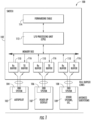
- FIG. 1 depicts an overview of an avionics full-duplex switched Ethernet data network 100 according to example embodiments of the present disclosure.
- Data network 100 includes a full-duplex switching device 102, end systems 104, 106, 108, and host computing devices 105, 107, 109.
- end systems 104, 106, 108 can provide an interface between host computing devices 105, 107, 109, and switching device 102.
- host computing devices 105, 107, 109 may transmit data over the network (e.g., to switching device 102) using one or more communication ports associated with end systems 104, 106, 108.
- End systems 104, 106, 108 can transmit the data to switching device 102 via one or more full-duplex communication links.
- Switching device 102 can then route the data to one or more intended destinations. For instance, data received from host computing device 105 may be routed to host computing device 107, host computing device 109, or other computing device associated with the data network 100.
- switching device 102 may communicate with any suitable number of host computing devices without deviating from the scope of the present disclosure.
- data network 100 may include any suitable number of switching devices without deviating from the scope of the present disclosure.
- Each host computing device may be associated with one or more applications. For instance, as shown, host computing device 105 is associated with an autopilot application and host computing device 107 is associated with a heads-up display application. Host computing device 109 can be associated with various other systems and/or applications.
- Host computing devices 105, 107, 109 can determine one or more data messages and can transmit the data messages to switch device 102 through the corresponding end systems 104, 106, 108. For instance, as indicated the data messages may be transmitted to switching device 102 through a full-duplex link, such as two category 5 UTP twisted pairs.
- the data messages can be received by switching device 102 through receive buffers 110.
- receive buffers 110 can store multiple data packets in first-in, first-out (FIFO) order.
- the data packets can be provided to an I/O processing unit 112 via a memory bus.
- processing unit 112 can be configured to analyze each packet stored in receive buffers 110 and to determine a destination address for the packets. For instance, in implementations, wherein the receive buffers 110 are FIFO buffers, processing unit 112 can analyze each arriving packet based at least in part on the order of arrival of the packets. In some implementations, processing unit 112 can determine the destination address for the packets based at least in part on a virtual link identifier (VLID) encoded in the packet. The VLID can be indicative of a source end system and one or more destination end systems associated with the data packets.
- VLID virtual link identifier
- the packet can be provided to a forwarding table 114.
- Forwarding table 114 can indicate one or more transmit buffers 116 to which the packet should be sent. For instance, forwarding table 114 can provide a mapping of VLIDs to transmission buffers 116 and/or destination end systems.
- the packet can then be copied to the appropriate transmission buffer(s) through the memory bus, and transmitted on an outgoing link associated with the transmission buffer. For instance, the outgoing link may link the switch to an end system or to another switching device.
- transmission buffers 116 can be FIFO buffers. In such implementations, the data packets can be transmitted by the transmission buffers 116 based at least in part on the order of arrival at the transmission buffers.
- a host computing device may be associated with multiple applications.
- a host computing device may include two or more subsystems. Each subsystem can be associated with an independent application.
- the subsystems can be implemented as partitions of the host computing device.
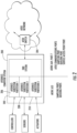
- FIG. 2 depicts an end system 200 interfacing with a host computing device 202 that includes three independent partitions.
- end system 200 can provide a connection between host computing device 202 and a switching device 204.
- Switching device 204 can correspond to switching device 102 of FIG. 1 or other switching device.
- Host computing device 202 supports subsystems 206, 208, 210.
- subsystems 206, 208, and 210 can be implemented as partitions 1, 2, and 3, respectively.
- Partitions 1-3 can provide isolation between subsystems 206-210 within host computing device 202. For instance, the isolation can be achieved by restricting the address space of each partition. The isolation can further be achieved by restricting the time allotted to each partition. In this manner, partitions 1-3 can correspond to spatial partitions and/or temporal partitions.
- partitions 1-3 may be configured to receive one or more signals from one or more controllers, sensors, and/or actuators. Partitions 1-3 may further be configured to determine one or more data messages based at least in part on such signals, and to provide the data messages to one or more other computing devices over the data network. As described above, such data messages may be transmitted or received through communication ports associated with one or more end systems and/or switching devices in a data network.
- FIG. 3 depicts port configurations of end systems 302, 304, 306 in a data network 300.
- each end system 302, 304, 306 includes communication ports 308, and UDP ports 310.
- Data network 300 further includes virtual links 312, 314, and 316.
- virtual links 312, 314, 316 provide a link from end system 302 to end system 304 and/or end system 306.
- data network 300 can include any suitable number of virtual links between end systems 302, 304, 306.
- virtual links 312, 314, 316 may be routed through one or more switching devices, such as switching device 102, or switching device 204.
- End systems 302, 304, 306 can interface with one or more partitions associated with a host computing device.
- each partition may include one or more API ports 318.
- Each API port 318 may correspond to a communication port 308.
- Each communication port 308 may further correspond to a UDP port 310.
- each partition can have one source IP address and one destination IP address associated with each communication port. In this manner, a partition can have multiple IP addresses corresponding to multiple communication ports.
- an AFDX message can be identified by its associated UDP source and destination port numbers, its IP source and destination addresses as well as its MAC destination address which encodes the VL.
- each communication port can be configured as a sampling port, a queuing port, or a service access point (SAP) port.
- each partition can be configured operate in accordance with the ARINC-653 protocol.
- ARINC-653 defines sampling and queuing ports.
- End systems 302, 304, 306 can be configured to provide a suitable communications interface for supporting sampling and queuing ports.
- end systems 302, 304, 306 can operate in accordance with the ARINC-664 protocol (Part 7).
- ARINC-664 defines sampling and queuing ports to correspond to the ARINC-653 sampling and queuing ports, respectively.
- ARINC-664 further provides SAP ports that can be used for communication between components in the avionics full-duplex switched Ethernet (AFDX) data network and non-AFDX components.
- AFDX full-duplex switched Ethernet
- a sampling port can include buffer storage for a single message. In this manner, arriving messages may overwrite a message currently stored in the buffer. Reading a message from a sampling port does not remove the message from the buffer. In this manner, a message stored in the sampling port can be read multiple times.
- a queuing port can include sufficient storage for multiple messages. For instance, the number of messages that the queuing port is capable of storing can be specified as a configuration parameter. New messages can be appended to the buffer queue. Reading from a queuing port removes the message from the queue (e.g., on a FIFO basis).
- FIG. 4 depicts a set of virtual ports according to example embodiments of the present disclosure.
- FIG. 4 depicts receive (Rx) ports A, B, C, D, and transmit (Tx) ports A, B, C, D.
- each port has a corresponding virtual port.
- virtual receive port 0 corresponds to Rx port C
- virtual receive port 1 corresponds to Rx port D, etc.
- the set of virtual ports can be defined and memory mapped to one or more memory addresses 402 in a memory space associated with the end system.
- each virtual port in the set of virtual ports may be configured to have a fixed definition in the memory map associated with the end system.
- the virtual ports can be configured individually and assigned specific port parameters.
- Each virtual port can further be associated with a unique set of buffers and/or registers necessary for communication with the corresponding Rx or Tx port.
- Each memory mapped virtual port can be accessed independently.
- the virtual ports can act as a "window" into the Rx and Tx ports.
- the parameters associated with a virtual port can define the corresponding Rx or Tx port associated with virtual port.
- the port parameters can include parameters indicative of a virtual link, a sub-virtual link, a UDP source port, a UDP destination port, a destination partition, etc.
- each Tx or Rx port can be associated with a subsystem partition associated with the host computing device.
- each virtual port can be allocated to a contiguous address space using a memory management unit (MMU). In this manner, each partition can have protected access to its associated ports through use of the MMU without requiring a system call to the operating system associated with the end system and/or host computing device.
- MMU memory management unit
- the Tx and Rx ports can be managed on a virtual port basis. For instance, for transmission by a Tx port, the end system may assign a port identifier to the message at transmission of the message based at least in part on the corresponding virtual port. As another example, for reception by an Rx port, each received message can be mapped to the virtual port. In this manner, the message can be associated with the virtual port.
- FIG. 5 depicts a flow diagram of an example method (500) of providing a virtual port interface for an end system of an avionics data transfer system according to example embodiments of the present disclosure.
- the method (500) can be implemented using one or more computing devices, such as one or more of the computing devices of FIGS. 1 and 2 .
- the method or portions of the method can be implemented at least in part by other devices or components without deviating from the scope of the present disclosure.
- FIG. 5 depicts steps performed in a particular order for purposes of illustration and discussion.
- method (500) can include defining a set of virtual ports associated with an end system of an avionics full-duplex switched Ethernet (AFDX) data network.
- AFDX data network may include one or more host computing devices and one or more switching devices.
- the data network can further include one or more end systems configured to provide an interface between the host device(s) and the switching device(s).
- the host device(s) can be configured to communicate with the switching device(s) through one or more communication ports associated with the end system(s).
- the set of virtual ports can include any suitable number of virtual ports. For instance, in some implementations, the number of virtual ports can be determined based at least in part on one or more system configurations of the data network and/or on an amount of available memory space in the end system. In some implementations, a fixed number of virtual ports can be specified for an end system. The virtual ports may then be enabled or disabled based at least in part on one or more system requirements.
- method (500) can include mapping each virtual port to one or more memory addressees in a memory space associated with the end system.
- mapping each virtual port to one or more memory addresses in the memory space can include allocating or assigning each virtual port in the set of virtual ports a fixed definition in the memory space.
- a subset of the virtual ports can be mapped to the memory space.
- the virtual ports may be mapped to the memory space based at least in part on one or more port configurations associated with the end system.
- the amount of allotted memory space can be determined based at least in part on the size of data messages to be communicated through the data network. For instance, the size of the memory space can be fixed to allow the largest message size (e.g., 8 kilobytes) along with any necessary registers.
- method (500) can include identifying one or more system configurations associated with the data network.
- the system configurations can include a number of host computing devices, switching devices, end systems, partitions, etc., to be implemented in the data network.
- the system configurations can further include a number of physical ports that are implemented in the end system, and/or a number of ports that will be enabled to communicate with switching device(s) and/or host computing device(s). In this manner, the set of virtual ports can be tailored to the system requirements and/or characteristics of the data network.
- method (500) can include associating one or more virtual ports in the set of virtual ports with one or more physical ports of the end system based at least in part on the one or more system configurations.
- the virtual ports can be associated with one or more physical ports that will be implemented within the data network as indicated by the one or more system configurations.
- associating one or more virtual ports with one or more physical ports can include specifying, assigning or otherwise allocating one or more port parameters defining the corresponding physical ports to the virtual ports.
- the port parameters can include virtual link parameters, sub-virtual link parameters, a UDP source port, a UDP destination port, a destination partition, etc. In this manner, the parameters of the physical port can be associated with the corresponding memory mapped virtual port.
- the one or more virtual ports may further be configured to be associated with one or more buffers and/or registers used by the physical ports. For instance, a virtual port may be associated with each buffer and/or register required for interfacing with the corresponding physical port. In this manner, the one or more virtual ports may be assigned or allocated one or more buffers and/or registers and can act as an independent window or proxy for the physical port.
- the virtual ports can be allocated contiguously using an MMU. In this manner, each partition associated with the physical port can have unprotected access to the corresponding virtual ports (e.g., and thereby with the corresponding physical ports) through the MMU without needing the port access to be managed by the operating system.
Landscapes
- Engineering & Computer Science (AREA)
- Theoretical Computer Science (AREA)
- Signal Processing (AREA)
- Computer Networks & Wireless Communication (AREA)
- General Engineering & Computer Science (AREA)
- General Physics & Mathematics (AREA)
- Physics & Mathematics (AREA)
- Human Computer Interaction (AREA)
- Health & Medical Sciences (AREA)
- Computing Systems (AREA)
- General Health & Medical Sciences (AREA)
- Medical Informatics (AREA)
- Computer Security & Cryptography (AREA)
- Small-Scale Networks (AREA)
- Information Transfer Systems (AREA)
- Bus Control (AREA)
- Computer And Data Communications (AREA)
Applications Claiming Priority (2)
| Application Number | Priority Date | Filing Date | Title |
|---|---|---|---|
| US14/990,965 US10050765B2 (en) | 2016-01-08 | 2016-01-08 | Providing an interface for an avionics data transfer system |
| EP17150525.8A EP3190524A1 (de) | 2016-01-08 | 2017-01-06 | Bereitstellung einer schnittstelle für ein avionikdatenübertragungssystem |
Related Parent Applications (1)
| Application Number | Title | Priority Date | Filing Date |
|---|---|---|---|
| EP17150525.8A Division EP3190524A1 (de) | 2016-01-08 | 2017-01-06 | Bereitstellung einer schnittstelle für ein avionikdatenübertragungssystem |
Publications (2)
| Publication Number | Publication Date |
|---|---|
| EP4404072A2 true EP4404072A2 (de) | 2024-07-24 |
| EP4404072A3 EP4404072A3 (de) | 2024-10-30 |
Family
ID=57799543
Family Applications (2)
| Application Number | Title | Priority Date | Filing Date |
|---|---|---|---|
| EP17150525.8A Ceased EP3190524A1 (de) | 2016-01-08 | 2017-01-06 | Bereitstellung einer schnittstelle für ein avionikdatenübertragungssystem |
| EP24177051.0A Pending EP4404072A3 (de) | 2016-01-08 | 2017-01-06 | Bereitstellung einer schnittstelle für ein avionik-datenübertragungssystem |
Family Applications Before (1)
| Application Number | Title | Priority Date | Filing Date |
|---|---|---|---|
| EP17150525.8A Ceased EP3190524A1 (de) | 2016-01-08 | 2017-01-06 | Bereitstellung einer schnittstelle für ein avionikdatenübertragungssystem |
Country Status (4)
| Country | Link |
|---|---|
| US (1) | US10050765B2 (de) |
| EP (2) | EP3190524A1 (de) |
| BR (1) | BR102017000297A2 (de) |
| CA (1) | CA2953612C (de) |
Families Citing this family (5)
| Publication number | Priority date | Publication date | Assignee | Title |
|---|---|---|---|---|
| FR3050086A1 (fr) * | 2016-04-11 | 2017-10-13 | Airbus Operations Sas | Reseau de communication embarque d'un aeronef et systeme de communication |
| US10129143B2 (en) * | 2016-10-25 | 2018-11-13 | The Boeing Company | Bandwidth on deterministic aircraft data networks |
| CN111432899B (zh) | 2017-09-19 | 2022-04-15 | Bae系统控制有限公司 | 用于管理对共享端口的多核访问的系统和方法 |
| US11192662B2 (en) | 2018-11-13 | 2021-12-07 | Kidde Technologies, Inc. | Aircraft integrated modular avionics inter-partition communications simulation modeling language extension |
| CN110912840B (zh) * | 2019-11-24 | 2021-06-29 | 苏州浪潮智能科技有限公司 | 基于交换机端口的统一接口装置及底层设备信息获取方法 |
Family Cites Families (10)
| Publication number | Priority date | Publication date | Assignee | Title |
|---|---|---|---|---|
| US7787486B2 (en) * | 2006-11-13 | 2010-08-31 | Honeywell International Inc. | Method and system for achieving low jitter in real-time switched networks |
| US7929431B2 (en) | 2007-03-19 | 2011-04-19 | Honeywell International Inc. | Port rate smoothing in an avionics network |
| US8953438B2 (en) * | 2010-07-30 | 2015-02-10 | Honeywell International Inc. | Multiple source virtual link reversion in safety critical switched networks |
| US9008113B2 (en) | 2010-12-20 | 2015-04-14 | Solarflare Communications, Inc. | Mapped FIFO buffering |
| US20130208630A1 (en) * | 2012-02-15 | 2013-08-15 | Ge Aviation Systems Llc | Avionics full-duplex switched ethernet network |
| US8923320B2 (en) * | 2012-12-10 | 2014-12-30 | Dell Products L.P. | Systems and methods for automating virtual network interface controller configuration during workload provisioning |
| US10819791B2 (en) | 2013-10-11 | 2020-10-27 | Ge Aviation Systems Llc | Data communications network for an aircraft |
| CN104601427B (zh) | 2013-10-31 | 2018-03-06 | 新华三技术有限公司 | 数据中心网络中的报文转发方法及装置 |
| US9858007B2 (en) | 2013-11-12 | 2018-01-02 | Avago Technologies General Ip (Singapore) Pte. Ltd. | Decoupling host and device address maps for a peripheral component interconnect express controller |
| US9306865B2 (en) * | 2014-03-12 | 2016-04-05 | Oracle International Corporation | Virtual port mappings for non-blocking behavior among physical ports |
-
2016
- 2016-01-08 US US14/990,965 patent/US10050765B2/en active Active
-
2017
- 2017-01-05 CA CA2953612A patent/CA2953612C/en not_active Expired - Fee Related
- 2017-01-06 BR BR102017000297-7A patent/BR102017000297A2/pt not_active IP Right Cessation
- 2017-01-06 EP EP17150525.8A patent/EP3190524A1/de not_active Ceased
- 2017-01-06 EP EP24177051.0A patent/EP4404072A3/de active Pending
Also Published As
| Publication number | Publication date |
|---|---|
| CA2953612A1 (en) | 2017-07-08 |
| EP3190524A1 (de) | 2017-07-12 |
| US10050765B2 (en) | 2018-08-14 |
| BR102017000297A2 (pt) | 2017-11-21 |
| CA2953612C (en) | 2019-05-14 |
| US20170201367A1 (en) | 2017-07-13 |
| EP4404072A3 (de) | 2024-10-30 |
Similar Documents
| Publication | Publication Date | Title |
|---|---|---|
| CA2953612C (en) | Providing an interface for an avionics data transfer system | |
| US7016352B1 (en) | Address modification within a switching device in a packet-switched network | |
| US9479461B2 (en) | Computer system and method for communicating data between computers | |
| US7899052B1 (en) | Memory structure for resolving addresses in a packet-based network switch | |
| US9847954B2 (en) | Distributed method of data acquisition in an AFDX network | |
| US20100199275A1 (en) | Server switch integration in a virtualized system | |
| US9094333B1 (en) | Systems and methods for sending and receiving information via a network device | |
| US20240422100A1 (en) | Virtual cxl switch | |
| CN113366459B (zh) | 用于车载数据传送的具有端点和直接存储器访问控制器的网络交换机 | |
| CN107483370A (zh) | 一种在fc网络上传输ip和can业务的方法 | |
| US20100002714A1 (en) | PCI express network | |
| EP3136633B1 (de) | Netzwerkmodul zum senden und/oder empfang von datenpaketen von einer netzwerkeinrichtung und verfahren | |
| CN104579863A (zh) | 用于飞机的数据通信网络 | |
| US10454656B1 (en) | AFDX switch supporting multiple types of data traffic | |
| CN104579864A (zh) | 用于飞机的数据通信网络 | |
| US10205610B2 (en) | Uplink packet routing in a system-on-a-chip base station architecture | |
| KR101794719B1 (ko) | Sdn 기반 네트워크 가상화 플랫폼에서의 ip 주소 가상화 방법 및 시스템 | |
| US10355993B2 (en) | Safe network interface | |
| US6480490B1 (en) | Interleaved access to address table in network switching system | |
| CN117675722A (zh) | 一种基于确定性以太网跨频段硬实时的转发方法 | |
| CN109462530A (zh) | 一种基于RS422总线和Slip协议的飞机数字音频传输方法 | |
| CN111385016B (zh) | 用于航空电子通信系统的交换机及航空电子通信系统 | |
| WO2002005494A1 (en) | High speed packet processing architecture | |
| US12401729B1 (en) | Internal communications within a network device | |
| US20260089241A1 (en) | Data type separation for aircraft mission systems digital backbone |
Legal Events
| Date | Code | Title | Description |
|---|---|---|---|
| PUAI | Public reference made under article 153(3) epc to a published international application that has entered the european phase |
Free format text: ORIGINAL CODE: 0009012 |
|
| STAA | Information on the status of an ep patent application or granted ep patent |
Free format text: STATUS: THE APPLICATION HAS BEEN PUBLISHED |
|
| AC | Divisional application: reference to earlier application |
Ref document number: 3190524 Country of ref document: EP Kind code of ref document: P |
|
| AK | Designated contracting states |
Kind code of ref document: A2 Designated state(s): AL AT BE BG CH CY CZ DE DK EE ES FI FR GB GR HR HU IE IS IT LI LT LU LV MC MK MT NL NO PL PT RO RS SE SI SK SM TR |
|
| PUAL | Search report despatched |
Free format text: ORIGINAL CODE: 0009013 |
|
| AK | Designated contracting states |
Kind code of ref document: A3 Designated state(s): AL AT BE BG CH CY CZ DE DK EE ES FI FR GB GR HR HU IE IS IT LI LT LU LV MC MK MT NL NO PL PT RO RS SE SI SK SM TR |
|
| RIC1 | Information provided on ipc code assigned before grant |
Ipc: G06F 13/38 20060101AFI20240924BHEP |
|
| STAA | Information on the status of an ep patent application or granted ep patent |
Free format text: STATUS: REQUEST FOR EXAMINATION WAS MADE |
|
| 17P | Request for examination filed |
Effective date: 20250416 |