EP4404330A1 - Module de batterie rechargeable - Google Patents
Module de batterie rechargeable Download PDFInfo
- Publication number
- EP4404330A1 EP4404330A1 EP23216880.7A EP23216880A EP4404330A1 EP 4404330 A1 EP4404330 A1 EP 4404330A1 EP 23216880 A EP23216880 A EP 23216880A EP 4404330 A1 EP4404330 A1 EP 4404330A1
- Authority
- EP
- European Patent Office
- Prior art keywords
- vent
- sensing part
- area
- length
- flow
- Prior art date
- Legal status (The legal status is an assumption and is not a legal conclusion. Google has not performed a legal analysis and makes no representation as to the accuracy of the status listed.)
- Granted
Links
Images


Classifications
-
- H—ELECTRICITY
- H01—ELECTRIC ELEMENTS
- H01M—PROCESSES OR MEANS, e.g. BATTERIES, FOR THE DIRECT CONVERSION OF CHEMICAL ENERGY INTO ELECTRICAL ENERGY
- H01M50/00—Constructional details or processes of manufacture of the non-active parts of electrochemical cells other than fuel cells, e.g. hybrid cells
- H01M50/20—Mountings; Secondary casings or frames; Racks, modules or packs; Suspension devices; Shock absorbers; Transport or carrying devices; Holders
- H01M50/204—Racks, modules or packs for multiple batteries or multiple cells
- H01M50/207—Racks, modules or packs for multiple batteries or multiple cells characterised by their shape
- H01M50/209—Racks, modules or packs for multiple batteries or multiple cells characterised by their shape adapted for prismatic or rectangular cells
-
- H—ELECTRICITY
- H01—ELECTRIC ELEMENTS
- H01M—PROCESSES OR MEANS, e.g. BATTERIES, FOR THE DIRECT CONVERSION OF CHEMICAL ENERGY INTO ELECTRICAL ENERGY
- H01M10/00—Secondary cells; Manufacture thereof
- H01M10/42—Methods or arrangements for servicing or maintenance of secondary cells or secondary half-cells
- H01M10/48—Accumulators combined with arrangements for measuring, testing or indicating the condition of cells, e.g. the level or density of the electrolyte
- H01M10/486—Accumulators combined with arrangements for measuring, testing or indicating the condition of cells, e.g. the level or density of the electrolyte for measuring temperature
-
- H—ELECTRICITY
- H01—ELECTRIC ELEMENTS
- H01M—PROCESSES OR MEANS, e.g. BATTERIES, FOR THE DIRECT CONVERSION OF CHEMICAL ENERGY INTO ELECTRICAL ENERGY
- H01M10/00—Secondary cells; Manufacture thereof
- H01M10/60—Heating or cooling; Temperature control
- H01M10/61—Types of temperature control
- H01M10/613—Cooling or keeping cold
-
- H—ELECTRICITY
- H01—ELECTRIC ELEMENTS
- H01M—PROCESSES OR MEANS, e.g. BATTERIES, FOR THE DIRECT CONVERSION OF CHEMICAL ENERGY INTO ELECTRICAL ENERGY
- H01M50/00—Constructional details or processes of manufacture of the non-active parts of electrochemical cells other than fuel cells, e.g. hybrid cells
- H01M50/20—Mountings; Secondary casings or frames; Racks, modules or packs; Suspension devices; Shock absorbers; Transport or carrying devices; Holders
- H01M50/204—Racks, modules or packs for multiple batteries or multiple cells
-
- H—ELECTRICITY
- H01—ELECTRIC ELEMENTS
- H01M—PROCESSES OR MEANS, e.g. BATTERIES, FOR THE DIRECT CONVERSION OF CHEMICAL ENERGY INTO ELECTRICAL ENERGY
- H01M50/00—Constructional details or processes of manufacture of the non-active parts of electrochemical cells other than fuel cells, e.g. hybrid cells
- H01M50/30—Arrangements for facilitating escape of gases
- H01M50/35—Gas exhaust passages comprising elongated, tortuous or labyrinth-shaped exhaust passages
- H01M50/358—External gas exhaust passages located on the battery cover or case
-
- H—ELECTRICITY
- H01—ELECTRIC ELEMENTS
- H01M—PROCESSES OR MEANS, e.g. BATTERIES, FOR THE DIRECT CONVERSION OF CHEMICAL ENERGY INTO ELECTRICAL ENERGY
- H01M50/00—Constructional details or processes of manufacture of the non-active parts of electrochemical cells other than fuel cells, e.g. hybrid cells
- H01M50/30—Arrangements for facilitating escape of gases
- H01M50/35—Gas exhaust passages comprising elongated, tortuous or labyrinth-shaped exhaust passages
- H01M50/367—Internal gas exhaust passages forming part of the battery cover or case; Double cover vent systems
-
- H—ELECTRICITY
- H01—ELECTRIC ELEMENTS
- H01M—PROCESSES OR MEANS, e.g. BATTERIES, FOR THE DIRECT CONVERSION OF CHEMICAL ENERGY INTO ELECTRICAL ENERGY
- H01M50/00—Constructional details or processes of manufacture of the non-active parts of electrochemical cells other than fuel cells, e.g. hybrid cells
- H01M50/30—Arrangements for facilitating escape of gases
- H01M50/375—Vent means sensitive to or responsive to temperature
-
- H—ELECTRICITY
- H01—ELECTRIC ELEMENTS
- H01M—PROCESSES OR MEANS, e.g. BATTERIES, FOR THE DIRECT CONVERSION OF CHEMICAL ENERGY INTO ELECTRICAL ENERGY
- H01M50/00—Constructional details or processes of manufacture of the non-active parts of electrochemical cells other than fuel cells, e.g. hybrid cells
- H01M50/50—Current conducting connections for cells or batteries
- H01M50/502—Interconnectors for connecting terminals of adjacent batteries; Interconnectors for connecting cells outside a battery casing
- H01M50/505—Interconnectors for connecting terminals of adjacent batteries; Interconnectors for connecting cells outside a battery casing comprising a single busbar
-
- H—ELECTRICITY
- H01—ELECTRIC ELEMENTS
- H01M—PROCESSES OR MEANS, e.g. BATTERIES, FOR THE DIRECT CONVERSION OF CHEMICAL ENERGY INTO ELECTRICAL ENERGY
- H01M50/00—Constructional details or processes of manufacture of the non-active parts of electrochemical cells other than fuel cells, e.g. hybrid cells
- H01M50/50—Current conducting connections for cells or batteries
- H01M50/502—Interconnectors for connecting terminals of adjacent batteries; Interconnectors for connecting cells outside a battery casing
- H01M50/507—Interconnectors for connecting terminals of adjacent batteries; Interconnectors for connecting cells outside a battery casing comprising an arrangement of two or more busbars within a container structure, e.g. busbar modules
-
- H—ELECTRICITY
- H01—ELECTRIC ELEMENTS
- H01M—PROCESSES OR MEANS, e.g. BATTERIES, FOR THE DIRECT CONVERSION OF CHEMICAL ENERGY INTO ELECTRICAL ENERGY
- H01M50/00—Constructional details or processes of manufacture of the non-active parts of electrochemical cells other than fuel cells, e.g. hybrid cells
- H01M50/50—Current conducting connections for cells or batteries
- H01M50/502—Interconnectors for connecting terminals of adjacent batteries; Interconnectors for connecting cells outside a battery casing
- H01M50/519—Interconnectors for connecting terminals of adjacent batteries; Interconnectors for connecting cells outside a battery casing comprising printed circuit boards [PCB]
-
- Y—GENERAL TAGGING OF NEW TECHNOLOGICAL DEVELOPMENTS; GENERAL TAGGING OF CROSS-SECTIONAL TECHNOLOGIES SPANNING OVER SEVERAL SECTIONS OF THE IPC; TECHNICAL SUBJECTS COVERED BY FORMER USPC CROSS-REFERENCE ART COLLECTIONS [XRACs] AND DIGESTS
- Y02—TECHNOLOGIES OR APPLICATIONS FOR MITIGATION OR ADAPTATION AGAINST CLIMATE CHANGE
- Y02E—REDUCTION OF GREENHOUSE GAS [GHG] EMISSIONS, RELATED TO ENERGY GENERATION, TRANSMISSION OR DISTRIBUTION
- Y02E60/00—Enabling technologies; Technologies with a potential or indirect contribution to GHG emissions mitigation
- Y02E60/10—Energy storage using batteries
Definitions
- aspects of embodiments of the present invention relate to a rechargeable battery module.
- a rechargeable battery is a battery repeatedly charged and discharged, unlike a primary battery.
- a small-capacity secondary battery may be used in a portable electronic device, such as a mobile phone, a laptop computer, and a camcorder.
- a large-capacity and high-density secondary battery may be used for a power source or energy storage, such as for driving a motor of a hybrid vehicle and an electric vehicle.
- the rechargeable battery may be used as a rechargeable battery module including a plurality of battery cells coupled in series and/or in parallel.
- the rechargeable battery module includes a plurality of battery cells and a temperature sensor attached to a central portion of the module.
- the temperature sensor detects the temperature of the battery cell. That is, the temperature sensor may measure the temperature of the battery cell by heat conduction transmitted through a short aluminium plate in contact with the body of the battery cell.
- the temperature sensor when the temperature sensor is installed in the central portion of the module, if the thermal runaway occurs in an edge battery cell, after the heat transferring between the battery cells with high heat capacity from the edge to the central portion, the temperature sensor detects the temperature. Therefore, there is a time delay from the fire occurrence to the detection.
- attaching the temperature sensor to each battery cell is not desirable in terms of cost and maintenance.
- a rechargeable battery module that senses a temperature of a battery cell and a temperature of a vent gas is provided. According to another aspect of embodiments of the present disclosure, a rechargeable battery module is provided that secures a long (i.e. more) time to respond to a fire by detecting a temperature of a battery cell in daily operating situations with a single temperature sensor and detecting a temperature of a vent gas when thermal runaway and events occur.
- a rechargeable battery module includes a plurality of battery cells stacked in a first direction; a bus bar holder including a bottom part covering the battery cells along a second direction crossing the first direction and exposing electrode terminals of the battery cells in a third direction crossing the first and second directions; a bus bar connecting the electrode terminals exposed by an exposure hole of the bus bar holder; and a temperature sensor arranged on an electrode terminal of the electrode terminals to detect a temperature of a battery cell of the battery cells, the temperature sensor including a first sensing part to transmit a detection signal through a body part connected to the first sensing part, the bus bar holder further including a vent pipe part connected to the bottom part in the second direction to define a vent passage toward a vent of the battery cells along the first direction, and the temperature sensor further including a second sensing part connected to the body part, extending through the vent pipe part, and exposed to the vent passage.
- the second sensing part may be connected to the first sensing part.
- the first sensing part may be formed of a plate having a first width corresponding to a width of the electrode terminal and a first length
- the second sensing part may be formed of a plate having a second width smaller than the first width and a length longer than the first length and exposed in a second length extending to the vent passage in the second direction.
- the second sensing part may be in contact with a flow of a vent gas with a thickness (t) in a direction that intersects the second direction and an outer surface area of the second width and the second length.
- the second sensing part may be in contact with the flow of the vent gas in a horizontally downward state to the vent with a first area (W2*L2) of the second width and the second length, and may be in contact with the flow of the vent gas in a vertical state to the vent with a second area (t*L2) that is smaller than the first area and having the thickness (t) and the second length (L2).
- the rechargeable battery module may further include a pair of end plates respectively arranged at opposite ends of the plurality of battery cells in the first direction; and a pair of side plates respectively arranged at opposite sides of the plurality of battery cells in the second direction to connect the pair of end plates to each other, wherein the bottom part of the bus bar holder is fixed to the pair of end plates and the pair of side plates.
- the second sensing part may be in contact with the flow of the vent gas with a first area (W2*L2) of a second width and a second length in a first angle downwardly inclined while going in the first direction with respect to the vent, and may be in contact with the flow of the vent gas in a first angle that slopes upward with respect to a vertical direction of the vent with a second area (t*L2) that is smaller than the first area and having the thickness (t) and the second length (L2).
- the second sensing part may be in contact with the flow of the vent gas in a second angle that slopes upward while going in the first direction with respect to the vent with a first area (W2*L2) of a second width and a second length, and in contact with the flow of the vent gas in a first angle that slopes downward with respect to a vertical direction of the vent with a second area (t*L2) that is smaller than the first area and having a thickness (t) and a second length (L2).
- the second sensing part may be in contact with the flow of the vent gas in a vertical state to the vent with a first area (W2*L2) of the second width and the second length, and in contact with the flow of vent gas in a horizontal state to the vent with a second area (t*L2) that is smaller than the first area and having a thickness (t) and a second length (L2).
- the second sensing part may include flow holes to distribute a vent gas to the vent in a horizontal state.
- the first sensing part of the temperature sensor is connected to the battery cell and the second sensing part is installed in the vent pipe part to be exposed to the vent passage, when a thermal runaway and/or an event occur, the temperature of the vent gas may be effectively sensed by contacting the vent gas with the second sensing part. Therefore, it is possible to secure a long time to respond to the fire, and the safety of the rechargeable battery module is improved.
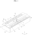
- FIG. 1 is a perspective view of a rechargeable battery module according to an embodiment of the present invention
- FIG. 2 is an exploded perspective view of the rechargeable battery module of FIG. 1
- a rechargeable battery module according to an embodiment includes a plurality of battery cells 10, a bus bar holder 20, a bus bar 40, and a temperature sensor 50.
- the rechargeable battery module further includes a pair of end plates 60 and a pair of side plates 70.
- the plurality of battery cells 10 are stacked in a first direction (e.g., an x-axis direction).
- a pair of end plates 60 are disposed at both ends of the first direction of the stacked battery cells 10 to set the flow and arrangement of the battery cells 10 in the first direction (e.g., the x-axis direction).
- a pair of side plates 70 are disposed at both sides of a second direction (e.g., a y-axis direction) of the battery cells 10 crossing the first direction, and are connected to the pair of end plates 60 to set the flow and arrangement of the of battery cells 10 in the second direction.
- a second direction e.g., a y-axis direction
- FIG. 3 is a perspective view of a temperature sensor applied to the rechargeable battery module of FIG. 1 and FIG. 2 .
- FIG. 4 is a cross-sectional view taken along the line IV-IV of FIG. 1 .
- the bus bar holder 20 includes a bottom part 21 for connection and insulation of electrode terminals 11 and 12, and a vent pipe part 22 for a discharge of a vent gas.
- the bottom part 21 is provided at both sides of the second direction, and the vent pipe part 22 is provided at the center of the second direction and connected to the bottom part 21 at both sides.
- the bottom part 21 covers the battery cells 10 while exposing the electrode terminals 11 and 12 of the battery cells 10 in a third direction (e.g., a z-axis direction) crossing the second direction on both sides of the second direction (e.g., the y-axis direction) crossing the first direction.
- the bottom part 21 has an exposure hole 211 in a part corresponding to the electrode terminals 11 and 12. Also, the bottom part 21 is fixed to the pair of end plates 60 and the pair of side plates 70.
- vent pipe part 22 forms a vent passage 23 towards vents 13 of the battery cells 10.
- the vent passage 23 is connected to the bottom part 21 in the second direction and is formed in an entire range of the rechargeable battery module along the first direction.
- the vent pipe part 22 has a pair of side walls 221 and 222 at both sides in the second direction and a ceiling 223 connecting upper ends of the pair of side walls 221 and 222. Therefore, in an embodiment, the vent passage 23 is an approximately rectangular passage defined by the pair of side walls 221 and 222 and the ceiling 223 of the vent pipe part 22 and surfaces around the vent 13 of the battery cells 10.
- the bus bar 40 electrically and mechanically connects the electrode terminals 11 and 12 exposed in the third direction through the exposure hole 211. That is, the bus bar 40 may connect the electrode terminals 11 and 12 of the battery cells 10 neighboring in the first direction in parallel or in series by welding, for example.
- the temperature sensor 50 is installed on the electrode terminals 11 and 12 of a battery cell 10 among the plurality of battery cells 10, and includes a first sensing part 51 and a second sensing part 52.
- the temperature sensor 50 is configured to detect a temperature of a battery cell 10 with the first sensing part 51 and transmit a detection signal to a battery management system (not shown) through a body part 53 connected to the first sensing part 51.
- the first and second sensing parts 51 and 52 may be connected to each other.
- the second sensing part 52 is connected to the body part 53, installed through the vent pipe part 22, exposed to the vent passage 23, and senses the temperature of the vent gas flowing through the vent passage 23.
- the first sensing part 51 senses the temperature of the battery cell 10 during a normal operation of the module.
- the second sensing part 52 senses the temperature of the vent gas when the vent gas of high temperature flows through the vent passage 23 in event conditions, such as a thermal runaway. During the normal operation of the module, the second sensing part 52 prepares for event conditions.
- the first sensing part 51 is formed of a plate having a first width W1 and a first length L1 corresponding to widths of the electrode terminals 11 and 12, and the second sensing part 52 is formed of a plate having a second width W2 smaller than the first width W1 and a length longer than the first length L1.
- the second sensing part 52 has a second length L2 extending inside the vent passage 23 in the second direction.
- the second sensing part 52 contacts the flow of the vent gas with a thickness t in the direction crossing the second direction (e.g., the y-axis direction) and an outer surface area of the second width W2 and the second length L2.
- FIG. 5 is a cross-sectional view of a vent flow path and a second sensing part taken along the line V-V of FIG. 1 .
- the temperature sensor 50 may be formed of a negative temperature coefficient thermistor.
- FIG. 6 is a temperature graph comparing comparative examples and an embodiment (a first embodiment) of the present invention.
- the temperature graph represents an average temperature for a vent passage volume.
- a comparative example 1 senses a temperature around a side wall of a vent pipe part during a cell event through a temperature sensor having only a first sensing part.
- a through-hole (not shown) is provided in a side wall of a vent pipe part, and a temperature is sensed around the through-hole of the side wall during a cell event through a temperature sensor having only a first sensing part. Both comparative examples 1 and 2 did not detect a large temperature increase even during the cell event.
- the second sensing part 52 penetrates the side wall 221 of the vent pipe part 22 to be inserted and installed into the vent passage 23 and the second sensing part 52 is in direct contact with the vent gas, a large temperature increase was detected during the cell event through the temperature sensor 50.
- the first embodiment may detect the large temperature increase during the cell event compared to the comparative examples 1 and 2.
- maximum detected temperatures are 110 and 120 degrees Celsius.
- the maximum detected temperature is shown to be a significantly higher, as 310 degrees Celsius, compared to the comparative examples 1 and 2.
- the first embodiment may quickly sense the event situation at the beginning of the cell event. Therefore, the first embodiment may secure a long time capable of responding to a fire. As such, the safety of the rechargeable battery module is improved.
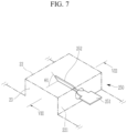
- FIG. 7 is a perspective view of a vent flow path and a second sensing part in a rechargeable battery module according to another embodiment of the present invention
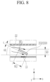
- FIG. 8 is a cross-sectional view taken along the line VIII-VIII of FIG. 7 .
- a second sensing part 252 may be inserted and installed into the side wall 221 of the vent pipe part 22 in a twisted state with a first angle ⁇ 1 outside the vent passage 23.
- a flow rate Q1 of the contacted vent gas may be increased.
- the second sensing part 252 increases the flow rate Q1 of the contacted vent gas while lowering the flow of the vent gas. Therefore, the embodiment may more quickly sense the event situation at the beginning of the cell event compared to the previously described embodiment.
- FIG. 9 is a cross-sectional view of a vent flow path and a second sensing part in a rechargeable battery module according to another embodiment of the present invention.
- a flow rate Q2 of the contact vent gas may be increased.
- the embodiment may more quickly sense the event situation at the beginning of the cell event compared to the first described embodiment.
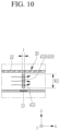
- FIG. 10 is a cross-sectional view of a vent flow path and a second sensing part in a rechargeable battery module according to another embodiment of the present invention.
- the second sensing part 452 includes flow holes 453 through which the vent gas is distributed to the vent 13 in the horizontal state.
- the flow holes 453 are in contact the flow of the vent gas while circulating the vent gas.
- the vertical state of the second sensing part 452 increases (e.g., maximally increases) the flow rate of the vent gas in contact while applying the flow resistance to the vent gas, and the flow holes 453 circulate the vent gas to minimize or reduce an increase in the flow resistance.
- the second sensing part 452 maximizes or increases the flow rate of the contacted vent gas while circulating the flow of the vent gas. Therefore, the embodiment may more quickly sense the event situation at the beginning of the cell event compared to the first described embodiment.
Landscapes
- Chemical & Material Sciences (AREA)
- Chemical Kinetics & Catalysis (AREA)
- Electrochemistry (AREA)
- General Chemical & Material Sciences (AREA)
- Engineering & Computer Science (AREA)
- Manufacturing & Machinery (AREA)
- Battery Mounting, Suspending (AREA)
Applications Claiming Priority (1)
| Application Number | Priority Date | Filing Date | Title |
|---|---|---|---|
| KR1020230006357A KR20240114211A (ko) | 2023-01-16 | 2023-01-16 | 이차 전지 모듈 |
Publications (2)
| Publication Number | Publication Date |
|---|---|
| EP4404330A1 true EP4404330A1 (fr) | 2024-07-24 |
| EP4404330B1 EP4404330B1 (fr) | 2025-10-15 |
Family
ID=89222887
Family Applications (1)
| Application Number | Title | Priority Date | Filing Date |
|---|---|---|---|
| EP23216880.7A Active EP4404330B1 (fr) | 2023-01-16 | 2023-12-14 | Module de batterie rechargeable |
Country Status (5)
| Country | Link |
|---|---|
| US (1) | US20240243377A1 (fr) |
| EP (1) | EP4404330B1 (fr) |
| KR (1) | KR20240114211A (fr) |
| CN (1) | CN118352668A (fr) |
| PL (1) | PL4404330T3 (fr) |
Families Citing this family (1)
| Publication number | Priority date | Publication date | Assignee | Title |
|---|---|---|---|---|
| CN119340524B (zh) * | 2024-09-19 | 2025-12-12 | 华为数字能源技术有限公司 | 电池包和储能柜 |
Citations (3)
| Publication number | Priority date | Publication date | Assignee | Title |
|---|---|---|---|---|
| EP2849252A1 (fr) * | 2013-09-13 | 2015-03-18 | Samsung SDI Co., Ltd. | Bloc-batteries |
| EP3321994A1 (fr) * | 2015-07-09 | 2018-05-16 | Hitachi Automotive Systems, Ltd. | Module de pile |
| CN218182435U (zh) * | 2021-08-20 | 2022-12-30 | 蜂巢能源科技股份有限公司 | 电池模组、电池包和车辆 |
-
2023
- 2023-01-16 KR KR1020230006357A patent/KR20240114211A/ko active Pending
- 2023-10-16 US US18/487,808 patent/US20240243377A1/en active Pending
- 2023-12-14 EP EP23216880.7A patent/EP4404330B1/fr active Active
- 2023-12-14 PL PL23216880.7T patent/PL4404330T3/pl unknown
-
2024
- 2024-01-04 CN CN202410015126.XA patent/CN118352668A/zh active Pending
Patent Citations (3)
| Publication number | Priority date | Publication date | Assignee | Title |
|---|---|---|---|---|
| EP2849252A1 (fr) * | 2013-09-13 | 2015-03-18 | Samsung SDI Co., Ltd. | Bloc-batteries |
| EP3321994A1 (fr) * | 2015-07-09 | 2018-05-16 | Hitachi Automotive Systems, Ltd. | Module de pile |
| CN218182435U (zh) * | 2021-08-20 | 2022-12-30 | 蜂巢能源科技股份有限公司 | 电池模组、电池包和车辆 |
Also Published As
| Publication number | Publication date |
|---|---|
| CN118352668A (zh) | 2024-07-16 |
| US20240243377A1 (en) | 2024-07-18 |
| PL4404330T3 (pl) | 2026-02-23 |
| EP4404330B1 (fr) | 2025-10-15 |
| KR20240114211A (ko) | 2024-07-23 |
Similar Documents
| Publication | Publication Date | Title |
|---|---|---|
| JP7418410B2 (ja) | 電池モジュール | |
| US20230246262A1 (en) | Battery module and battery pack comprising same | |
| KR102421779B1 (ko) | 전지 시스템 | |
| EP4064433B1 (fr) | Bloc-batterie | |
| EP3706189B1 (fr) | Module de batterie et bloc batterie | |
| CN113574727A (zh) | 电池模块 | |
| KR20220030545A (ko) | 배터리 모듈 | |
| JP7418409B2 (ja) | 電池モジュール | |
| US12482872B2 (en) | Battery module and battery pack including the same | |
| EP4404330A1 (fr) | Module de batterie rechargeable | |
| US20250357578A1 (en) | Battery Module and Battery Pack Including the Same | |
| CN115699428A (zh) | 电池组和包括该电池组的车辆 | |
| CN113950768B (zh) | 包括外部短路设备和冷却设备的电池模块系统 | |
| US10826043B2 (en) | Cell connection unit and battery module comprising the same | |
| KR102693863B1 (ko) | 내진동성이 향상된 배터리 팩 | |
| US11342633B2 (en) | Current collecting system for battery module, battery module, and vehicle | |
| US20250379282A1 (en) | Battery system including improved electrical connecting elements | |
| EP4618253A1 (fr) | Bloc-batterie à structure de délai d'allumage | |
| CN121548897A (zh) | 具有防火结构的电池模块及包括其的电池组 | |
| KR20260048055A (ko) | 배터리 모듈 및 그를 포함하는 배터리 팩 | |
| KR20250170360A (ko) | 배터리 셀 어셈블리 및 이를 포함하는 배터리 팩 | |
| KR20230107039A (ko) | 열 확산 방지 기능이 구비된 전지 팩 | |
| CN121586962A (zh) | 电池电芯组件及其制造方法 | |
| KR20250022427A (ko) | 배터리 모듈 및 이를 포함하는 배터리 팩 | |
| KR20260037228A (ko) | 배터리 셀 교체 검출 장치 및 방법 |
Legal Events
| Date | Code | Title | Description |
|---|---|---|---|
| PUAI | Public reference made under article 153(3) epc to a published international application that has entered the european phase |
Free format text: ORIGINAL CODE: 0009012 |
|
| STAA | Information on the status of an ep patent application or granted ep patent |
Free format text: STATUS: REQUEST FOR EXAMINATION WAS MADE |
|
| 17P | Request for examination filed |
Effective date: 20231214 |
|
| AK | Designated contracting states |
Kind code of ref document: A1 Designated state(s): AL AT BE BG CH CY CZ DE DK EE ES FI FR GB GR HR HU IE IS IT LI LT LU LV MC ME MK MT NL NO PL PT RO RS SE SI SK SM TR |
|
| GRAP | Despatch of communication of intention to grant a patent |
Free format text: ORIGINAL CODE: EPIDOSNIGR1 |
|
| STAA | Information on the status of an ep patent application or granted ep patent |
Free format text: STATUS: GRANT OF PATENT IS INTENDED |
|
| INTG | Intention to grant announced |
Effective date: 20250723 |
|
| GRAS | Grant fee paid |
Free format text: ORIGINAL CODE: EPIDOSNIGR3 |
|
| GRAA | (expected) grant |
Free format text: ORIGINAL CODE: 0009210 |
|
| STAA | Information on the status of an ep patent application or granted ep patent |
Free format text: STATUS: THE PATENT HAS BEEN GRANTED |
|
| AK | Designated contracting states |
Kind code of ref document: B1 Designated state(s): AL AT BE BG CH CY CZ DE DK EE ES FI FR GB GR HR HU IE IS IT LI LT LU LV MC ME MK MT NL NO PL PT RO RS SE SI SK SM TR |
|
| REG | Reference to a national code |
Ref country code: GB Ref legal event code: FG4D Ref country code: CH Ref legal event code: F10 Free format text: ST27 STATUS EVENT CODE: U-0-0-F10-F00 (AS PROVIDED BY THE NATIONAL OFFICE) Effective date: 20251015 |
|
| REG | Reference to a national code |
Ref country code: DE Ref legal event code: R096 Ref document number: 602023007537 Country of ref document: DE |
|
| REG | Reference to a national code |
Ref country code: IE Ref legal event code: FG4D |
|
| PGFP | Annual fee paid to national office [announced via postgrant information from national office to epo] |
Ref country code: DE Payment date: 20251210 Year of fee payment: 3 |
|
| PGFP | Annual fee paid to national office [announced via postgrant information from national office to epo] |
Ref country code: AT Payment date: 20260113 Year of fee payment: 3 |
|
| PGFP | Annual fee paid to national office [announced via postgrant information from national office to epo] |
Ref country code: FR Payment date: 20251208 Year of fee payment: 3 |
|
| REG | Reference to a national code |
Ref country code: NL Ref legal event code: MP Effective date: 20251015 |
|
| PGFP | Annual fee paid to national office [announced via postgrant information from national office to epo] |
Ref country code: HU Payment date: 20260112 Year of fee payment: 3 |
|
| REG | Reference to a national code |
Ref country code: AT Ref legal event code: MK05 Ref document number: 1847843 Country of ref document: AT Kind code of ref document: T Effective date: 20251015 |
|
| PG25 | Lapsed in a contracting state [announced via postgrant information from national office to epo] |
Ref country code: NL Free format text: LAPSE BECAUSE OF FAILURE TO SUBMIT A TRANSLATION OF THE DESCRIPTION OR TO PAY THE FEE WITHIN THE PRESCRIBED TIME-LIMIT Effective date: 20251015 |
|
| PG25 | Lapsed in a contracting state [announced via postgrant information from national office to epo] |
Ref country code: ES Free format text: LAPSE BECAUSE OF FAILURE TO SUBMIT A TRANSLATION OF THE DESCRIPTION OR TO PAY THE FEE WITHIN THE PRESCRIBED TIME-LIMIT Effective date: 20251015 |
|
| REG | Reference to a national code |
Ref country code: LT Ref legal event code: MG9D |
|
| PG25 | Lapsed in a contracting state [announced via postgrant information from national office to epo] |
Ref country code: NO Free format text: LAPSE BECAUSE OF FAILURE TO SUBMIT A TRANSLATION OF THE DESCRIPTION OR TO PAY THE FEE WITHIN THE PRESCRIBED TIME-LIMIT Effective date: 20260115 |
|
| PG25 | Lapsed in a contracting state [announced via postgrant information from national office to epo] |
Ref country code: FI Free format text: LAPSE BECAUSE OF FAILURE TO SUBMIT A TRANSLATION OF THE DESCRIPTION OR TO PAY THE FEE WITHIN THE PRESCRIBED TIME-LIMIT Effective date: 20251015 Ref country code: HR Free format text: LAPSE BECAUSE OF FAILURE TO SUBMIT A TRANSLATION OF THE DESCRIPTION OR TO PAY THE FEE WITHIN THE PRESCRIBED TIME-LIMIT Effective date: 20251015 Ref country code: AT Free format text: LAPSE BECAUSE OF FAILURE TO SUBMIT A TRANSLATION OF THE DESCRIPTION OR TO PAY THE FEE WITHIN THE PRESCRIBED TIME-LIMIT Effective date: 20251015 |
|
| PG25 | Lapsed in a contracting state [announced via postgrant information from national office to epo] |
Ref country code: RS Free format text: LAPSE BECAUSE OF FAILURE TO SUBMIT A TRANSLATION OF THE DESCRIPTION OR TO PAY THE FEE WITHIN THE PRESCRIBED TIME-LIMIT Effective date: 20260115 |
|
| PG25 | Lapsed in a contracting state [announced via postgrant information from national office to epo] |
Ref country code: IS Free format text: LAPSE BECAUSE OF FAILURE TO SUBMIT A TRANSLATION OF THE DESCRIPTION OR TO PAY THE FEE WITHIN THE PRESCRIBED TIME-LIMIT Effective date: 20260215 |