EP4406665A1 - Collier destiné à être utilisé avec un pistolet de distribution - Google Patents
Collier destiné à être utilisé avec un pistolet de distribution Download PDFInfo
- Publication number
- EP4406665A1 EP4406665A1 EP24153267.0A EP24153267A EP4406665A1 EP 4406665 A1 EP4406665 A1 EP 4406665A1 EP 24153267 A EP24153267 A EP 24153267A EP 4406665 A1 EP4406665 A1 EP 4406665A1
- Authority
- EP
- European Patent Office
- Prior art keywords
- collar
- connecting member
- flexible container
- receiving
- opening
- Prior art date
- Legal status (The legal status is an assumption and is not a legal conclusion. Google has not performed a legal analysis and makes no representation as to the accuracy of the status listed.)
- Pending
Links
Images




Classifications
-
- B—PERFORMING OPERATIONS; TRANSPORTING
- B05—SPRAYING OR ATOMISING IN GENERAL; APPLYING FLUENT MATERIALS TO SURFACES, IN GENERAL
- B05C—APPARATUS FOR APPLYING FLUENT MATERIALS TO SURFACES, IN GENERAL
- B05C17/00—Hand tools or apparatus using hand held tools, for applying liquids or other fluent materials to, for spreading applied liquids or other fluent materials on, or for partially removing applied liquids or other fluent materials from, surfaces
- B05C17/005—Hand tools or apparatus using hand held tools, for applying liquids or other fluent materials to, for spreading applied liquids or other fluent materials on, or for partially removing applied liquids or other fluent materials from, surfaces for discharging material from a reservoir or container located in or on the hand tool through an outlet orifice by pressure without using surface contacting members like pads or brushes
- B05C17/00503—Details of the outlet element
- B05C17/00506—Means for connecting the outlet element to, or for disconnecting it from, the hand tool or its container
- B05C17/00509—Means for connecting the outlet element to, or for disconnecting it from, the hand tool or its container of the bayonet type
-
- B—PERFORMING OPERATIONS; TRANSPORTING
- B05—SPRAYING OR ATOMISING IN GENERAL; APPLYING FLUENT MATERIALS TO SURFACES, IN GENERAL
- B05C—APPARATUS FOR APPLYING FLUENT MATERIALS TO SURFACES, IN GENERAL
- B05C17/00—Hand tools or apparatus using hand held tools, for applying liquids or other fluent materials to, for spreading applied liquids or other fluent materials on, or for partially removing applied liquids or other fluent materials from, surfaces
- B05C17/005—Hand tools or apparatus using hand held tools, for applying liquids or other fluent materials to, for spreading applied liquids or other fluent materials on, or for partially removing applied liquids or other fluent materials from, surfaces for discharging material from a reservoir or container located in or on the hand tool through an outlet orifice by pressure without using surface contacting members like pads or brushes
- B05C17/00583—Hand tools or apparatus using hand held tools, for applying liquids or other fluent materials to, for spreading applied liquids or other fluent materials on, or for partially removing applied liquids or other fluent materials from, surfaces for discharging material from a reservoir or container located in or on the hand tool through an outlet orifice by pressure without using surface contacting members like pads or brushes the container for the material to be dispensed being deformable
Definitions
- the present invention relates to a collar for use with a dispensing gun, in particular a for dispensing gun used with flexible containers of a viscous fluid such as a sealant.
- sealant containers There is also often a requirement to apply sealant in locations with restricted space, however re-usable guns for sealant containers are typically bulky and unwieldy which can be problematic in restricted spaces such as around sinks or in bathroom environments.
- GB2374070(ARMISHAW ) discloses a dispenser suitable for dispensing sealant, comprises a body in which material to be dispensed is located, dispensing means operable to urge the material through an outlet in the body, a unitary end cap removably attached to the body and a nozzle removably attachable to the end cap.
- DE202018107157U1 discloses a screw sleeve for a cartridge having a cylindrical cartridge connecting portion with an internal bayonet thread for connection to a cylindrical screw sleeve connecting portion with an external bayonet thread of a cartridge in order to connect the screw sleeve to the cartridge by means of a bayonet closure, as well as a cylindrical mixer holding section with a central mixer holding opening in order to hold a mixer on the cartridge, characterized by a stiffening measure and/or a pressing device in order to increase the pressing pressure generated by the bayonet lock with which the mixer is pressed against the cartridge.
- EP 1 611 962 discloses a receiving body for a spray gun system comprises a fixing support for fixing a nozzle to which a guiding cone is connected, wherein the cone progresses into a radially extending support edge and a system consisting of a spray gun with the receiving body arranged between a nozzle and a bag.
- the support edge may be formed as a peripheral flange and/or have a thread for fixing the nozzle.
- US2022/0274758A1 discloses a foil cartridge with a film bag and a sold head part.
- US2019/0299245A1 discloses a storage container for a cylindrical tube of viscous material including a body dimensioned to receive a cylindrical tube and a nozzle.
- US2017/0327299A1 discloses an assembly for pressing pastry or a fluid substance from a film bag with a cylindrical receptacle and a closing cap.
- US6223941B1 discloses an apparatus to dispense material from a soft packet with a barrel and a cap.
- GB2374070A discloses a dispense for sealant with a dispensing means to urge material through an outlet on a body with an end cap that receives a nozzle.
- a collar for use with a dispensing gun comprising: a body with an egress aperture provided at a first end and an opening for receiving a flexible container at a second opposed end; wherein the egress aperture has a first connection means for receiving a nozzle and the opening has a second connection means comprising a plurality of receptor slots for receiving lugs on an external surface of a connecting member to form a bayonet connection.
- a collar for use with a dispensing gun comprising: a body with an egress aperture provided at a first end and an opening for receiving a flexible container at a second opposed end; wherein the egress aperture has a first connection means for receiving a nozzle and the opening has a second connection means comprising a plurality of lugs on an external surface for receiving receptor slots on a connecting member to form a bayonet connection.
- the collar can be repeatedly reused as part of a dispensing gun assembly wherein an end of flexible container is received to the opening of the collar, contents of the container exit through the egress aperture under urging until the flexible container is spent and compressed into a parcel that fits within the depth of the collar.
- the collar can be removed whilst still containing the parcel, the parcel can be removed and a new container can be added and the collar reconnected and reused.
- this minimises waste as only the skin surrounding the contents of the container is disposed of whilst the collar and other parts of the dispensing gun can be reused.
- the collar is therefore suited to dispensing extrudable contents such as viscous fluids contained in flexible containers.
- the flexible containers are typically collapsible, flexible, cylindrical sausage-shaped containers, commonly known in the art, such as foil pack that is received and contained by the cavity defined by the collar and connecting member.
- the connecting member is a rigid cylinder.
- the body is substantially cylindrical with an egress aperture which provides a channel along which contents exit the collar.
- the egress aperture is at a first end of the collar which is an end from which the content is dispense and applied.
- the egress aperture has a first connection means for receiving a nozzle so that a nozzle can be easily added and removed as required. This allows for a nozzle to be easily changed at any time and also allows for the nozzle to be removed cleaned and reused.
- the opening for receiving a flexible container is provided at the second opposed end of the cylindrical body.
- the opening is shaped and dimensioned to receive an end of a flexible container.
- the opening has a second connection means comprising: a plurality of receptor slots for receiving lugs on an external surface of a connecting member to form a bayonet connection, or a plurality of lugs on an external surface of the opening for receiving receptor slots on the connecting member to form a bayonet connection.
- the engagement with the receptor slots is external to the container which helps to ensures that contents of the flexible container are not liable to interfere with or compromise the connection or be snagged by the lugs.
- the collar has receptor slots and fits externally about the connecting member which has corresponding lugs so that the internal profile of the connecting member is a continuous smooth surface of a first diameter and the collar has a wider second diameter.
- this enables the flexible container to not become caught between the joint and instead acts to encourage the flexible container to expand into wider diameter space at the collar so that the sealing material can be smoothly extruded and it is efficiently extruded until fully spent.
- the distal end of the cylinder may taper towards the collar to present a substantially smooth continuous surface rather than a stepped surface. It is appreciated that the distal end of the cylinder may taper to minimum thickness that provides sufficient robustness for repeated connection and disconnection of the collar.
- the collar and connecting member can be provided in a reverse configuration in some embodiments in which the collar with external lugs is received into the connecting member that has corresponding receptor slots.
- the connecting member may also be shaped to provide a smooth internal profile of a first diameter and the collar may be shaped to have a wider second diameter.
- proximal end of the collar may taper towards the connecting member to present a substantially smooth continuous surface rather than a stepped surface. It is appreciated that the proximal end of the collar may taper to minimum thickness that provides sufficient robustness for repeated connection and disconnection of the collar.
- bayonet connection enables the overlapping portion to be thinner than the thickness required for a screw thread connection that provides the same strength and durability.
- this provides the option for the external circumference where the collar and connecting member join to be less than traditional assemblies which have a screw threaded cap that receives the nozzle and has a much wider circumference. Therefore the present invention is more suitable for use in space restricted areas, such as behind taps or under window sills because the collar region has a smaller circumference.
- the first connection means on the egress aperture is a screw thread.
- the screw thread is provided on an external face of the egress aperture for engagement with an internal screw thread on the nozzle.
- the collar has a shoulder that is a region of the body at the first end that tapers towards the egress aperture. This shaping assists with urging contents from the flexible container towards and through the egress aperture.
- the shoulder is formed by shaping of the wall of the collar.
- tapering that forms the shoulder may be provided by an internal thickening of the wall of the collar so that the external profile is different to the internal profile.
- the collar has at least one radially projecting fin to provide a grip for a user's hand when attaching and removing the collar from the connecting member using the bayonet connection.
- a plurality of regularly spaced fins are provided around the circumference of the collar.
- the depth of the body is dimensioned to accommodate a spent flexible container.
- a spent flexible container typically at least part of the body that has a constant diameter must be the depth of a spent container so that it can be fully contained in the collar. Therefore in an embodiment that has a shoulder, the shoulder depth is not considered as part of the depth for storing the spent container as the diameter is not constant.
- part of the collar that receives the spent container and that has a constant diameter is at least 20mm long and no greater than 30mm long.
- a region of the collar with a constant diameter has a depth of 25mm.
- the depth of the collar also helps to ensure that any leakage from the flexible container is retained in the collar and does not spread to the cylinder (connecting member, which could also make separation of the bayonet connection problematic.
- each receptor slot is L-shaped extending from an edge of the opening. Different embodiments of the collar may have different lengths of receptor slot.
- each receptor slot is L-shaped extending from an edge (distal end) of the connecting member.
- each receptor slot extends at least 8mm inwards from the edge of the opening or connecting member.
- each receptor slot extends at least 10mm inwards from the edge of the opening or connecting member.
- each receptor slot extends at least 12mm inwards from the edge of the opening or connecting member.
- the longer receptor slots may be required to provide improved strength when using more heavy duty sealants, that can have a thicker consistency, which places more pressure onto the bayonet connection when the sealants is being squeezed through the nozzle compared to lower viscosity contents such as sanitary silicones.
- the larger 12mm receptor slots may be used for thicker consistency sealants that also typically use larger threaded universal nozzles and the 8mm receptor slots may be used for a thinner consistency sealant for example when using the smaller 'sanitary' type threaded universal nozzles.
- the bayonet fitting may contain a detent mechanism to provide a sensation to confirm connection, such as audible click or haptic feedback.
- a detent mechanism to provide a sensation to confirm connection, such as audible click or haptic feedback.
- this may be achieved by a ball detent provided as part of the receptor slot/lug connection.
- the collar and a connecting member are assembled to provide a cavity in which a flexible container is received and the assembly is for use as part of a dispensing gun.
- a typical dispending gun has a cradle for holding the collar and connecting member that receives the flexible container.
- the dispending gun also has an urging means to force fluid from the flexible container through the egress aperture as the flexible container is compressed by part of the urging means.
- the urging means is a plunger activated by a trigger handle.
- the plunger may be shaped and dimensioned to cup an end of the flexible container and guide contents towards the collar.
- the trigger handle operates by means of a ratchet to enable incremental controlled release of fluid from the flexible container.
- a distal end of the connecting member has a connection means that is associated with the dispending gun to assist with seating the cylinder on the dispensing gun.
- an end of the cylinder has a screw thread for connecting to an end cap on the dispending gun.
- the cylinder has an external screw thread and the end cap has an internal screw thread.
- a collar 3 With reference to the figures are shown different embodiments a collar 3.
- the collar is shown connected to a cylinder 2 (connecting member) and arranged in a dispending gun 99.
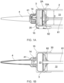
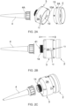
- FIGS. 1 and 2 there is shown a collar 3, a cylinder 2 and a nozzle 4.
- the collar 3 is a form of end cap that is received over a distal end 2A of the cylinder 2.
- the distal end 2A of the cylinder 2 and a proximal end 10A of the opening 10 overlap so that the proximal end of the opening 10A is external to the distal end 2A of the cylinder 2.
- the receptor slots 12 and lugs 13 are arranged in this overlapping region, wherein the lugs 13 project from an external face of the distal end 2A of the cylinder 2.
- the collar 3 has a body 3A with an egress aperture 41 provided at a first end A and an opening 10 for receiving a flexible container (not shown) at a second opposed end B.
- the egress aperture 41 has a first connection means 14 for receiving a nozzle 4.
- the connection means 14 is an external screw thread.
- the opening 10 has a second connection means comprising a plurality of receptor slots 12 for receiving lugs 13 on an external surface of the connecting member 2 to form a bayonet connection (12, 13).
- the collar 3 and cylinder 2 join together to form a cavity 19 in which a flexible container is received.
- the collar 3 is shown with a first diameter C and the cylinder 2 has a second diameter D.
- Diameter C is the diameter of the collar 3 is wider than the diameter D of the cylinder 2.
- the spent container becomes compressed in the collar 3 that has the slightly wider diameter C.
- the flexible container is compressed in the cavity 19 by a plunger 62 to urge contents from the egress aperture 41 through the nozzle 4 so that contents are dispensed and the spent flexible container ends in the volume 20 defined by the collar 3.
- the collar 3 is shaped and dimensioned to accommodate a spent flexible container.
- the connecting member 2 is a short cylinder that in use would be bonded at manufacture to a tube to provide the required cavity 19 for the flexible container.
- the point at which the parts are bonded is shown by reference 30.
- the connecting member 2 is shown as a complete cylindrical part that is dimensioned to receive the flexible container.
- the cylinder 2 has a thickened band 11 at the distal end 2A which includes the lugs 13.
- the band 11 provides the required strength and robustness for repeated connection and disconnection to a collar 3.
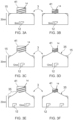
- Figures 3A to 3F show different collars.
- Figures 3A, 3C and 3E have a first egress aperture diameter and
- Figures 3B, 3D and 3F have a second egress aperture diameter.
- the diameter may be varied for different content and/or different applications.
- the collar 3 has two L-shaped receptor slots 12 arranged opposite to one another.
- the length of the receipt slots 12 is 8mm.
- the depth of the collar 3 that has a constant diameter for receiving the spent container is 30mm.
- the collar 3 has two L-shaped receptor slots 12 arranged opposite to one another.
- the length of the receipt slots 12 is 12mm.
- the depth of the collar 3 that has a constant diameter for receiving the spent container is 30mm.
- the collar 3 has four L-shaped receptor slots 12 arranged as opposed pairs.
- the length of the receipt slots 12 is 10mm.
- the depth of the collar 3 that has a constant diameter for receiving the spent container is 20mm.
- the collars 3 shown in Figure 3C, 3D, 3E and 3F all have a shoulder 35 that slopes (tapers in diameter) towards the egress aperture 14 to guide contents.
- the shoulder 35 in Figures 3C and 3D is sloped to a lesser degree than the shoulder 35 in Figures 3E and 3F .
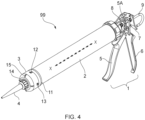
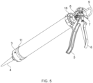
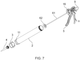
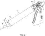
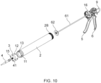
- Figures 4 to 11 show different embodiments of a collar 3 and cylinder 2 arranged in a dispending gun 99. Like parts have like references.
- the cylinder 2 has a longitudinal axis X-X and a plunger 62 driven by an urging means 1 acts to compress the flexible container within the cavity 19 to end up in the void 20 of the collar 3, so that content are forced from the container out via the agrees aperture and connected nozzle 4.
- the flexible container compresses along axis X from a first elongate filled configuration to a second short spent configuration.
- the egress aperture 14 that is connected to the nozzle 4 provides a fluid communication pathway from the container to the area of application of the content being dispensed.
- the cylinder 2 is rigid.
- the cylinder may be formed from a strong durable material, examples may include aluminium or a translucent or transparent synthetic plastic such as acrylonitrile butadiene styrene (ABS) or similar.
- ABS acrylonitrile butadiene styrene
- the collar 3, cylinder 2, and nozzle 4 assembly is shown connected to an urging means 1 which together form a dispensing gun 99.
- the urging means 1 which is a pumping mechanism known commonly in the art is used to urge content from the container.
- the urging means 1 has an end cap 16 into which a proximal end 2B of the cylinder 2 is received and connected. In the pictured embodiment, connection is by screw thread (see Figure 10 ).
- the dispensing gun 99 has a pumping handle formed by a base arm 6 and a lever action pumping arm 5. Movement (pumping) of the pumping arm 5 about a pin 5A drives a rod 61 connected to a plunger 62. The rod 61 passes through a hole in the end cap and is driven by pumping the pumping arm 5 against the base arm 6.
- the urging means 1 has a moveable plunger 62 which begins at the proximal end of the cylinder to a distal end 2A that is adjacent to the collar 3. The plunger is driven along the longitudinal axis X of the cylinder 2 by the rod 61 towards the collar 3.
- the plunger 62 In the first filled configuration the plunger 62 is near the end cap 16, and in the second spent configuration the plunger 62 is near the collar 3.
- the preferred flexible container for use this the dispensing gun 99 is a foil pack as is known in the art of sealants, such as used for silicone or bathroom sealants.
- the rod 61 and thereby the plunger 62 is urged by a spring 8 (see figures 7 and 9 ).
- the rod 61 and plunger 62 can be released by pressing the catch 7 (see figure 9 ) and pulling the hooked bar end 9 away from the collar 3, in a manner known in the art.
- the cylinder 2 is connected to the end cap 16.
- the cylinder is typically loaded by inserting a container into the cavity 19, opening the end of the container and connecting the collar 2 by the bayonet connection means 12,13.
- the pictured bayonet connection 12, 13 has lugs 13 extending from the external surface of the cylinder 2, and L shaped slots 12 in the sidewall of the collar 3.
- the distal end of the cylinder 2A which includes the lugs 13 has a thickened annular band 11, against which the collar at least partially overlaps to form the bayonet connection.
- the annular band 11 further provides rigidity and maintains the shape of the cylinder end 2A to ensure that when force is applied to the container within the cylinder, or if the cylinder is dropped or knocked that this will not compromise the connection and potentially lead to leakage.
- the pictured collars have fins 15 for a user to grip to help with connection and removal of the collar 3 from the cylinder 2.
- Each pictured collar 3 has four radially projecting fins 15 that project outwards so as to provide a means of providing purchase for use in rotating the collar and disconnecting from the cylinder 2, particularly after usage.
- the fins 15 are provided on the external surface of a domed first end A of the collar 3.
- the collar 3 may be envisaged to be formed in aluminium in some embodiments or a synthetic plastic such as ABS.
- the nozzle 4 is envisaged to be a consumable, formed in synthetic plastic. Ideally the nozzle 4 has a thumbscrew turn cuff 4A of enlarged diameter to aid connection and removal of the nozzle from the first connecting means.
- the egress aperture 41 has a smaller diameter than that shown in the embodiment shown in figures 4 to 7 .
Landscapes
- Engineering & Computer Science (AREA)
- Mechanical Engineering (AREA)
- Coating Apparatus (AREA)
- Containers And Packaging Bodies Having A Special Means To Remove Contents (AREA)
Applications Claiming Priority (1)
| Application Number | Priority Date | Filing Date | Title |
|---|---|---|---|
| GB2300969.9A GB2626382B (en) | 2023-01-23 | 2023-01-23 | A viscous fluid dispensing device |
Publications (1)
| Publication Number | Publication Date |
|---|---|
| EP4406665A1 true EP4406665A1 (fr) | 2024-07-31 |
Family
ID=85383224
Family Applications (1)
| Application Number | Title | Priority Date | Filing Date |
|---|---|---|---|
| EP24153267.0A Pending EP4406665A1 (fr) | 2023-01-23 | 2024-01-22 | Collier destiné à être utilisé avec un pistolet de distribution |
Country Status (2)
| Country | Link |
|---|---|
| EP (1) | EP4406665A1 (fr) |
| GB (1) | GB2626382B (fr) |
Citations (9)
| Publication number | Priority date | Publication date | Assignee | Title |
|---|---|---|---|---|
| US6223941B1 (en) | 1999-07-19 | 2001-05-01 | The Boeing Company | Applicator for dispensing a soft package of material |
| GB2374070A (en) | 2001-04-05 | 2002-10-09 | Adshead Ratcliffe & Co Ltd | A dispenser |
| EP1611962A2 (fr) | 2004-07-01 | 2006-01-04 | Stahl GmbH | Adaptateur à recevoir un sachet tubulaire |
| US20170327299A1 (en) | 2014-09-23 | 2017-11-16 | Sika Technology Ag | Arrangement for pressing a pasty or fluid substance out of a film bag |
| DE202018107157U1 (de) | 2018-12-14 | 2019-01-02 | Dinol Gmbh | Schraubhülse für Kartusche |
| US20190299245A1 (en) | 2016-08-12 | 2019-10-03 | Craig M. Coe | Storage Container for Tube Viscous Construction Material |
| US10463413B2 (en) * | 2016-03-17 | 2019-11-05 | Heraeus Medical Gmbh | Storage and mixing system for pasty cement components and method therefor |
| US20220266291A1 (en) * | 2019-08-02 | 2022-08-25 | Sulzer Mixpac Ag | Cartridge assembly, sleeve, system and method of assembling a cartridge assembly |
| US20220274758A1 (en) | 2019-08-02 | 2022-09-01 | Medmix Switzerland Ag | Foil cartridge, support sleeve and cartridge system |
-
2023
- 2023-01-23 GB GB2300969.9A patent/GB2626382B/en active Active
-
2024
- 2024-01-22 EP EP24153267.0A patent/EP4406665A1/fr active Pending
Patent Citations (9)
| Publication number | Priority date | Publication date | Assignee | Title |
|---|---|---|---|---|
| US6223941B1 (en) | 1999-07-19 | 2001-05-01 | The Boeing Company | Applicator for dispensing a soft package of material |
| GB2374070A (en) | 2001-04-05 | 2002-10-09 | Adshead Ratcliffe & Co Ltd | A dispenser |
| EP1611962A2 (fr) | 2004-07-01 | 2006-01-04 | Stahl GmbH | Adaptateur à recevoir un sachet tubulaire |
| US20170327299A1 (en) | 2014-09-23 | 2017-11-16 | Sika Technology Ag | Arrangement for pressing a pasty or fluid substance out of a film bag |
| US10463413B2 (en) * | 2016-03-17 | 2019-11-05 | Heraeus Medical Gmbh | Storage and mixing system for pasty cement components and method therefor |
| US20190299245A1 (en) | 2016-08-12 | 2019-10-03 | Craig M. Coe | Storage Container for Tube Viscous Construction Material |
| DE202018107157U1 (de) | 2018-12-14 | 2019-01-02 | Dinol Gmbh | Schraubhülse für Kartusche |
| US20220266291A1 (en) * | 2019-08-02 | 2022-08-25 | Sulzer Mixpac Ag | Cartridge assembly, sleeve, system and method of assembling a cartridge assembly |
| US20220274758A1 (en) | 2019-08-02 | 2022-09-01 | Medmix Switzerland Ag | Foil cartridge, support sleeve and cartridge system |
Also Published As
| Publication number | Publication date |
|---|---|
| GB2626382B (en) | 2026-03-04 |
| GB202300969D0 (en) | 2023-03-08 |
| GB2626382A (en) | 2024-07-24 |
Similar Documents
| Publication | Publication Date | Title |
|---|---|---|
| US6328715B1 (en) | Unit dose low viscosity material dispensing system | |
| US8281956B2 (en) | Dispensing apparatus | |
| US5755362A (en) | Hand-held applicator with force limiting clutch | |
| CN101778781B (zh) | 双流体分配器 | |
| US7032790B2 (en) | Container, sealing cap and method for sealing a nozzle tip of a curable liquid dispensing container | |
| KR20090122353A (ko) | 점성 물질용 디스펜싱 장치 | |
| US4526490A (en) | Dispenser for flowable material | |
| EP1488758B1 (fr) | Cartouche de distribution | |
| US6435373B1 (en) | Caulking gun and cartridge structure | |
| US5368206A (en) | Dispensing apparatus for pasty substances | |
| EP1795145A1 (fr) | Cartouche de distribution avec poignée | |
| GB2374070A (en) | A dispenser | |
| CN116829099A (zh) | 用于从料筒输送材料的分配枪 | |
| CN101296756B (zh) | 管筒式分配器 | |
| KR102916036B1 (ko) | 튜브형 실리콘 토출용 카트리지 | |
| GB2626382A (en) | A viscous fluid dispensing device | |
| US20250263205A1 (en) | Dispensing containter with brush applicator | |
| EP2227272B1 (fr) | Canule de distribution de produits fluides, en particulier pour applications rectales | |
| HK1123009B (en) | Cartridge dispenser | |
| HK1123009A1 (en) | Cartridge dispenser | |
| GB2470207A (en) | Flowable-sealant cartridge with flexible nozzle | |
| GB2187798A (en) | Material dispenser | |
| WO2011132193A1 (fr) | Système de distribution de matériau | |
| GB2343640A (en) | Nozzle liner | |
| EP1258431A1 (fr) | Tube pour produits visqueux |
Legal Events
| Date | Code | Title | Description |
|---|---|---|---|
| PUAI | Public reference made under article 153(3) epc to a published international application that has entered the european phase |
Free format text: ORIGINAL CODE: 0009012 |
|
| STAA | Information on the status of an ep patent application or granted ep patent |
Free format text: STATUS: THE APPLICATION HAS BEEN PUBLISHED |
|
| AK | Designated contracting states |
Kind code of ref document: A1 Designated state(s): AL AT BE BG CH CY CZ DE DK EE ES FI FR GB GR HR HU IE IS IT LI LT LU LV MC ME MK MT NL NO PL PT RO RS SE SI SK SM TR |
|
| STAA | Information on the status of an ep patent application or granted ep patent |
Free format text: STATUS: REQUEST FOR EXAMINATION WAS MADE |
|
| 17P | Request for examination filed |
Effective date: 20241111 |
|
| RBV | Designated contracting states (corrected) |
Designated state(s): AL AT BE BG CH CY CZ DE DK EE ES FI FR GB GR HR HU IE IS IT LI LT LU LV MC ME MK MT NL NO PL PT RO RS SE SI SK SM TR |
|
| STAA | Information on the status of an ep patent application or granted ep patent |
Free format text: STATUS: EXAMINATION IS IN PROGRESS |
|
| 17Q | First examination report despatched |
Effective date: 20250925 |
|
| GRAP | Despatch of communication of intention to grant a patent |
Free format text: ORIGINAL CODE: EPIDOSNIGR1 |
|
| STAA | Information on the status of an ep patent application or granted ep patent |
Free format text: STATUS: GRANT OF PATENT IS INTENDED |
|
| INTG | Intention to grant announced |
Effective date: 20260507 |
|
| GRAS | Grant fee paid |
Free format text: ORIGINAL CODE: EPIDOSNIGR3 |
|
| GRAA | (expected) grant |
Free format text: ORIGINAL CODE: 0009210 |
|
| STAA | Information on the status of an ep patent application or granted ep patent |
Free format text: STATUS: THE PATENT HAS BEEN GRANTED |