EP4407128A1 - Ensemble poignée de porte de véhicule électrique - Google Patents
Ensemble poignée de porte de véhicule électrique Download PDFInfo
- Publication number
- EP4407128A1 EP4407128A1 EP23153791.1A EP23153791A EP4407128A1 EP 4407128 A1 EP4407128 A1 EP 4407128A1 EP 23153791 A EP23153791 A EP 23153791A EP 4407128 A1 EP4407128 A1 EP 4407128A1
- Authority
- EP
- European Patent Office
- Prior art keywords
- lever
- vehicle door
- extremity
- handle assembly
- door handle
- Prior art date
- Legal status (The legal status is an assumption and is not a legal conclusion. Google has not performed a legal analysis and makes no representation as to the accuracy of the status listed.)
- Pending
Links
- 230000004913 activation Effects 0.000 claims abstract description 24
- 238000004904 shortening Methods 0.000 claims description 3
- 230000003213 activating effect Effects 0.000 claims description 2
- 230000000712 assembly Effects 0.000 description 5
- 238000000429 assembly Methods 0.000 description 5
- 230000005540 biological transmission Effects 0.000 description 1
- 230000008602 contraction Effects 0.000 description 1
- 230000000750 progressive effect Effects 0.000 description 1
- 230000001360 synchronised effect Effects 0.000 description 1
Images




Classifications
-
- E—FIXED CONSTRUCTIONS
- E05—LOCKS; KEYS; WINDOW OR DOOR FITTINGS; SAFES
- E05B—LOCKS; ACCESSORIES THEREFOR; HANDCUFFS
- E05B77/00—Vehicle locks characterised by special functions or purposes
- E05B77/42—Means for damping the movement of lock parts, e.g. slowing down the return movement of a handle
-
- E—FIXED CONSTRUCTIONS
- E05—LOCKS; KEYS; WINDOW OR DOOR FITTINGS; SAFES
- E05B—LOCKS; ACCESSORIES THEREFOR; HANDCUFFS
- E05B85/00—Details of vehicle locks not provided for in groups E05B77/00 - E05B83/00
- E05B85/10—Handles
- E05B85/107—Pop-out handles, e.g. sliding outwardly before rotation
-
- E—FIXED CONSTRUCTIONS
- E05—LOCKS; KEYS; WINDOW OR DOOR FITTINGS; SAFES
- E05B—LOCKS; ACCESSORIES THEREFOR; HANDCUFFS
- E05B81/00—Power-actuated vehicle locks
- E05B81/02—Power-actuated vehicle locks characterised by the type of actuators used
- E05B81/04—Electrical
- E05B81/06—Electrical using rotary motors
-
- E—FIXED CONSTRUCTIONS
- E05—LOCKS; KEYS; WINDOW OR DOOR FITTINGS; SAFES
- E05B—LOCKS; ACCESSORIES THEREFOR; HANDCUFFS
- E05B81/00—Power-actuated vehicle locks
- E05B81/54—Electrical circuits
- E05B81/56—Control of actuators
- E05B81/58—Control of actuators including time control, e.g. for controlling run-time of electric motors
-
- E—FIXED CONSTRUCTIONS
- E05—LOCKS; KEYS; WINDOW OR DOOR FITTINGS; SAFES
- E05B—LOCKS; ACCESSORIES THEREFOR; HANDCUFFS
- E05B81/00—Power-actuated vehicle locks
- E05B81/54—Electrical circuits
- E05B81/64—Monitoring or sensing, e.g. by using switches or sensors
- E05B81/76—Detection of handle operation; Detection of a user approaching a handle; Electrical switching actions performed by door handles
-
- E—FIXED CONSTRUCTIONS
- E05—LOCKS; KEYS; WINDOW OR DOOR FITTINGS; SAFES
- E05B—LOCKS; ACCESSORIES THEREFOR; HANDCUFFS
- E05B81/00—Power-actuated vehicle locks
- E05B81/54—Electrical circuits
- E05B81/90—Manual override in case of power failure
-
- E—FIXED CONSTRUCTIONS
- E05—LOCKS; KEYS; WINDOW OR DOOR FITTINGS; SAFES
- E05B—LOCKS; ACCESSORIES THEREFOR; HANDCUFFS
- E05B85/00—Details of vehicle locks not provided for in groups E05B77/00 - E05B83/00
- E05B85/10—Handles
- E05B85/103—Handles creating a completely closed wing surface
-
- E—FIXED CONSTRUCTIONS
- E05—LOCKS; KEYS; WINDOW OR DOOR FITTINGS; SAFES
- E05B—LOCKS; ACCESSORIES THEREFOR; HANDCUFFS
- E05B15/00—Other details of locks; Parts for engagement by bolts of fastening devices
- E05B15/04—Spring arrangements in locks
- E05B2015/0448—Units of springs; Two or more springs working together
Definitions
- the present invention relates to a vehicle door assembly, in particular of the type with a handle translating from a rest position where the handle is retracted and a deployed position where the handle is deployed and can be taken in hand and opened.
- Such vehicle door handle assemblies with a handle translating between a rest position and a deployed position is becoming more common and requested by manufacturers.
- Such vehicle door handle assemblies are motorized by an electric actuator.
- Such electric vehicle door handle assemblies are expensive and are not suitable for entry-level vehicles due to their costs. Furthermore, these vehicle door handle assemblies may be blocked or unusable in case of electrical power supply failure.
- One aim of the present invention is to find an economic and improved alternative for vehicle door handle assemblies having a translative movement.
- the invention relates to a vehicle door handle assembly comprising a bracket and a handle, said handle comprising a first extremity and a second extremity opposed to the first extremity,
- the vehicle door handle assembly could comprise a switch activating the electrical actuating device, said switch being activated when the handle is pushed in its activation position.
- the switch and the electrical actuating device could be electrically connected directly to each other.
- the switch could be configured to be activated by the rotation of the second lever to its activation position.
- the second lever could comprise a protruding portion configured to push and activate the switch when the second lever is in its activation position.
- the extremity of the return lever could comprise an extended portion, and the electrical actuating device could comprise a rotating arm configured to push this extended portion and rotate the return lever.
- the second rod could comprise a first part connected to the return lever and a second part connected to the first lever, the first and second parts being configured to slide relative to each other so that the second rod can contract itself, shortening its length.
- the second rod could also comprise at least one stopper to avoid the extension of its length.
- the second rod could comprise at least one elastic mean to bring said second rod back to its original length.
- the return lever could be connected to a delay element which slows down the passive rotation of the return lever from its second to its first position.
- the first lever could comprise an elastic mean passively bringing back said first lever from its deployed position to its rest position.
- the second lever could comprise an elastic mean passively rotating said second lever toward its deployed position.
- the actuator could be connected to an electronic timer stopping the rotation of the actuator when the return lever is in its second position.
- the actuator could be configured to measure the current draw in function of the resistance to the rotation.
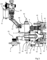
- FIGS 1a to 2b show a vehicle door handle assembly 1 in a rest position.
- the vehicle door handle assembly 1 comprises a bracket 10 and a handle 2.
- the bracket 10 is designed to be fixed on the vehicle door (not represented). In this rest position, the handle 2 is retracted into the bracket 10 in order to be at the same level of the door body when installed.
- the handle 2 comprises a first extremity 22 and a second extremity 23 opposed to the first extremity 22.
- the first extremity 22 of the handle 2 is connected to a first lever 3 and the second extremity 23 of the handle 2 is connected to a second lever 4.
- the first lever 3 is also designed to be connected to an opening lever (not represented) to open a latch of the vehicle door.
- the first lever 3 is designed to rotate between a rest position (represented in figures 1a and 2a ) where the first extremity 22 of the handle 2 is in a rest position, a deployed position (represented in figures 7a and 8a ) where the first extremity 22 of the handle 2 is in a deployed position outside the bracket 10 and an opening position (represented on figures 9 and 10 ) where the first lever 3 actuates the opening lever.
- the first lever 3 comprises a pivot connection 33 with the bracket 10 around which the first lever 3 rotates between its different positions.
- a first extremity of the first lever 3 is connected to the first extremity 22 of the handle 2 and a second extremity of the first lever 3, is connected to the opening lever, in particular, thanks to a pivot connection 31 and the shape of the first lever 3, the first lever 3 can touch the opening lever during the movement.
- the connection between the first lever 3 and the first extremity 22 of the handle is preferably a pivot-slide connection.
- the first extremity 22 of the handle 2 comprises a slide opening 21 and the first lever 3 comprises a recess 31 for example to receive a pin (not represented).
- the first lever 3 may also comprises an elastic mean (not represented) passively bringing back said first lever 3 from its deployed position to its rest position.
- This elastic mean may be a spring positioned for example on the pivot connection 33 between the first lever 3 and the bracket 10.
- the second extremity 23 of the handle 2 is connected to a second lever 4.
- the second lever 4 is designed to rotate between a rest position (represented in figures 1a and 2a ) where the second extremity 23 of the handle 2 is in a rest position and a deployed position (represented in figures 7a and 8a ) where the second extremity 23 of the handle 2 is in a deployed position outside the bracket 10.
- the second lever 4 comprises a pivot connection 41 with the bracket 10 around which the second lever 4 rotates between its different positions.
- a first extremity of the second lever 4 is connected to the second extremity 23 of the handle 2.
- This connection is preferably a pivot connection 24.
- the second lever 4 may also comprises an elastic mean (not represented) passively rotating said second lever 4 to its deployed position.
- This elastic mean may be a spring positioned for example on the pivot connection 41 between the second lever 4 and the bracket 10.
- the first 3 and second 4 levers may be connected together with at least one first rod 7 in order to synchronize the movements of the two levers 3, 4. More exactly, the first rod 7 transmits the rotation of the second lever 4 from its activation position to its deployed position to the first lever 3, rotating said first lever 3 from its rest position to its deployed position.
- the first rod 7 may comprises a pivot-slide connection with anyone of the first 3 or second lever 4 so that the first lever 3 can rotate from its rest position to its deployed position or from its deployed position to its opening position without rotating the second lever 4.
- the first rod 7 comprises a first extremity connected to a second extremity of the first lever 3 by a pivot connection 32.
- the first rod 7 comprises a second extremity connected to the second lever 4 by pivot-slide connection.
- the second extremity of the first rod 7 comprises a slide 71 and the second extremity of the second lever 4 comprises a pin 42 inserted into said slide 71.
- the handle 2, the first lever 3, the second 4 lever and the first rod 7 are designed and connected like a parallelogram and move together synchronously.
- the other connection of the first rod 7 with any of the first 3 or second lever 4 is preferably a pivot connection.
- the handle 2 is configured to have an activation position (illustrated in figures 5a to 6b ) where the handle 2 is pushed inside the bracket 10.
- the handle 2 may be pushed inside the bracket 10 in a short distance, for example inferior to 5mm, preferably 2mm or 3mm.
- the first 3 and second 4 levers rotate around their pivot connection 33 and 41 in a direction of rotation opposed to their deployed position, where the handle 2 is deployed, to an activation position of these two levers 3, 4.
- the handle 2 may be pushed in its activation position by a pression applied by a user.
- the vehicle door handle assembly 1 also comprises a return lever 5 having a first extremity connected to a second extremity of the second lever 4, said return lever 5 being designed to rotate between a first position (represented in figures 1a to 2b ) and a second position (represented in figures 7a to 8b ). More precisely, the return lever 5 comprises a pivot connection 55 with the bracket 10 around which the return lever 5 rotates between its different positions.
- the return lever 5 also comprises an elastic mean (not represented) passively bringing back said return lever 5 to its first position. This elastic mean may be a spring positioned for example on the pivot connection 55 between the return lever 5 and the bracket 10.
- the second lever 4 and the return lever 5 are connected together by a second 8 and a third 9 rods.
- the second rod 8 transmits the rotation of the second lever 4 from its rest position to its activation position to the return lever 5, rotating said return lever 5 from its first position to its second position.
- the third rod 9 transmits the rotation of the return lever 5 from its second position to its first position to the second lever 4, rotating said second lever 4 from its deployed position to its rest position.
- the second 8 and the third 9 rods are placed on the return lever 5 on either side of the pivot connection 55 of the return lever 5 with the bracket 10.
- the second 8 and the third 9 rods are placed on the second extremity of second lever 5 on the same side of the pivot connection 41 of the second lever 4 with the bracket 10.
- the second rod 8 may comprise a first part 81 connected to the return lever 5 and a second part 82 connected to the first lever 4.
- the first 81 and second 82 parts are configured to slide relative to each other so that the second rod 8 can contract itself, shortening its length.
- the second rod 8 also comprise at least one stopper 84 (visible in figure 4 ) to avoid the extension of its length.
- the second rod 8 may also comprise at least one elastic mean 83 to bring it back to its original length.
- the second rod 8 may comprise a pivot-slide connection 52 with anyone of the second lever 4 or return lever 5.
- the pivot-slide connection 52 is placed between the return lever 5 and the second rod 8.
- the return lever 5 comprises the slide of said pivot-slide connection 52 and the second rod 8 comprises a pin inserted in the slide.
- the connection between the second rod 8 and the second lever 4 is a pivot connection 44.
- the other connection of the second rod 8 with any of the second lever 4 or return lever 5 is preferably a pivot connection.
- the third rod 9 may comprises a pivot-slide connection 45 with any of the second lever 4 or return lever 5.
- the pivot-slide connection 45 is placed between the second lever 4 and the third rod 9.
- the second lever 4 comprises the slide of said pivot-slide connection 45 and the third rod 9 comprises a pin inserted in the slide.
- the connection between the third rod 9 and the return lever 5 is a pivot connection 53.
- the other connection of the third rod 9 with any of the second lever 4 or return lever 5 is preferably a pivot connection.
- the return lever 5, more exactly its second extremity, could be connected to a delay element 6 which slows down the passive rotation of the return lever 5 from its second to its first position.
- This delay element 6 may comprises at least one damper as illustrated in figures 1a to 10 .
- the at least one damper 6 may comprises a gearwheel 61 (visible in figure 3 ) and the extremity of the return lever 5, connected to the at least one damper 6, comprises an arc portion with teeth 54 engaged with said gearwheel 61.
- the vehicle door handle assembly 1 also comprises an electrical actuating device 100.
- This electrical actuating device 100 comprises an actuator 11 linked to the return lever 5 in order to move said return lever 5 from its first position to its second position.
- the return lever 5 may comprise an extended portion 56, for example on the same extremity of its arc portion with teeth 54, and the electrical actuating device 100 may comprise a rotating arm 12 configured to push this extended portion 56 to rotate the second lever 5.
- This extended portion 56 may also have a curved shape.
- the electrical actuating device 100 may also comprise some gears 13 for the connection between the actuator 11 and its rotating arm 12.
- the arm 12 may be only in contact with the extended portion 56 of the return lever 5 in order to push said return lever 5 to its second position.
- the electrical actuating device 100 may then rotate back to its initial position, freeing the contact with the return lever 5 and leaving it in its second position maintained by the damper 6. This single contact between the electrical actuating device 100 and the return lever 5 allows the second lever 5 rotating to its second position without the help of the electrical actuating device 100, for example by a push of the second extremity 23 of the handle 2 beyond its activation position.
- the vehicle door handle assembly 1 also comprises a switch 47 configured to activate the electrical actuating device 100.
- This switch 47 is activated when the handle 2 is pushed in its activation position. More precisely, the switch 47 may be configured to be activated by the rotation of the second lever 4 to its activation position.
- the second lever 4 may comprise a protruding portion 46 configured to push and activate the switch 47 when the second lever 4 is in its activation position.
- the switch 47 and the electrical actuating device 100 may be electrically connected directly to each other in order to avoid a connection with an electronical central unit of the vehicle and allows an autonomous functioning of the electrical actuating device 100.
- the actuator 11 could stop rotating according to different means.
- the actuator 11 may for example be connected to an electronic timer stopping the rotation of the actuator 11 when the return lever 5 is in its second position.
- the actuator 11 may also be configured to measure the current draw in function of the resistance to the rotation. When the return lever 5 is in its second position it stops and the resistance increases due to the second 8 and third 9 levers and its link with the second lever 4. This increase of the resistance of rotation may lead to an increase of the electrical current of the actuator 11 and may generate a signal to stop its rotation in order to avoid stalling of the electric motor.
- the actuating system may comprise one or both of these two means to determine when the second lever 5 is in its second position.
- the figures 1a to 10 represent different positions and cinematic steps of the deployment, opening and retractation of the handle 2.
- figures 1a to 2b are a representation of a rest position where the handle 2 is retracted into the bracket 10 in order to be at the same level of the door body when installed.
- the first lever 3 is in its rest position and maintained in this rest position by its elastic mean.
- the second lever 4 is in its rest position and the return lever 5 is in its first position.
- the return lever 5 is maintained in its first position by its elastic mean.
- the elastic mean of the return lever 5 is stronger than the elastic mean of the second lever 4 in order that the return lever 5 in its first position maintained the second lever 4 in its rest position.
- the elastic mean of the return lever 5 is also stronger than the delay element 6 in order to maintain the return lever 5 in its first position.
- Figures 5a to 6b represent an activation position of the handle 2 where the user activates the handle 2 by pushing the handle 2 into the bracket 10 through a short distance, for example inferior to 5mm, preferably 2mm or 3mm. Due to this push, the first 3 and second 4 levers rotate around their pivot connection 33 and 41 in a direction of rotation opposed to their deployed position. The push of the handle 2 is transmitted on both the first 3 and the second 4 levers due to the parallelogram configuration with the first rod 7. The rotation of the second lever 4 is not transmitted to the return lever 5 due to the contraction of the second rod 8 and the slide of the third rod 9 on its pivot-slide connection 45 between the second lever 4 and the third rod 9. The rotation of the second lever 5 activates the switch 47.
- the activation of the switch 47 commands the rotation of the electrical actuating device 100.
- the rotation of the electrical actuating device 100 causes the rotation of the return lever 5 around its pivot connection 55 with the bracket 10 from its first to its second position.
- the rotation of the first 3 and second 4 levers is made against the torque of their elastic means and the rotation of the return lever 5 is made against the torque of its elastic mean.
- the electrical actuating device 100 rotates back to its initial position (not represented in figures 5a to 6b ).
- Figures 7a to 8b represent a deployed position of the handle 2 where the first lever 3 and the second lever 4 have rotated from their activation position to their deployed position, bringing the handle 2 in its deployed position outside the bracket 10.
- the elastic mean of the second lever 4 allows the passive rotation of the second lever 4 to its deployed position.
- the rotation of the second lever 4 is transmitted to the first lever 3 by the first rod 7, rotating the first lever 3 to its deployed position.
- the rotation of the second lever 4 is not transmitted to the return lever 5 by any of the second 8 or third rod 9 which slide with their pivot-slide connections 52, 45.
- the first lever 3 is maintained in its deployed position due to the first rod 7 which is in abutment with its pivot-slide connection.
- the return lever 5 is still on its second position due to the delay element 6 or to the resistive torque of the electrical actuating device 100, especially the actuator 11.
- the third rod 9 is in abutment in order to stop the rotation of the second lever 4 in its deployed position against the torque of its elastic mean.
- Figures 9 and 10 represent an opening position of the handle 2 where the user can grab the handle 2 and pull it or has taken the handle 2 and pulled it in order to open the vehicle door.
- the handle 2 rotates around the pivot connection 24 between the second extremity 23 of the handle 2 and the second lever 4.
- the first extremity 22 of the handle 2 is pulled in an opening position rotating the first lever 3 from its deployed position to its opening position.
- the rotation of the first lever 3 is not transmitted to the second lever 4 by the first rod 7 due to its pivot-slide connection.
- the first lever 3 rotates back to its deployed position due to its elastic mean.
- the return lever 5 rotates from its second to its first position, it also transmits its rotation to the second lever 4 in order to rotate the second lever 4 from its deployed position to its rest position.
- the third rod 9 is in abutment in order to pull back the second lever 4 in its rest position against the torque of the elastic mean of the second lever4.
- the rotation of the second lever 4 and the first lever 3 to their rest position are synchronous due to the first rod 7.
- the handle 2 translates from its deployed position ( figures 7a to 8b ) to its rest position ( figures 1a to 2b ). This translation is slowed down and progressive thanks to the delay element 6.
Landscapes
- Lock And Its Accessories (AREA)
Priority Applications (2)
| Application Number | Priority Date | Filing Date | Title |
|---|---|---|---|
| EP23153791.1A EP4407128A1 (fr) | 2023-01-27 | 2023-01-27 | Ensemble poignée de porte de véhicule électrique |
| CN202410108779.2A CN118911542A (zh) | 2023-01-27 | 2024-01-25 | 电动车门把手组件 |
Applications Claiming Priority (1)
| Application Number | Priority Date | Filing Date | Title |
|---|---|---|---|
| EP23153791.1A EP4407128A1 (fr) | 2023-01-27 | 2023-01-27 | Ensemble poignée de porte de véhicule électrique |
Publications (1)
| Publication Number | Publication Date |
|---|---|
| EP4407128A1 true EP4407128A1 (fr) | 2024-07-31 |
Family
ID=85132733
Family Applications (1)
| Application Number | Title | Priority Date | Filing Date |
|---|---|---|---|
| EP23153791.1A Pending EP4407128A1 (fr) | 2023-01-27 | 2023-01-27 | Ensemble poignée de porte de véhicule électrique |
Country Status (2)
| Country | Link |
|---|---|
| EP (1) | EP4407128A1 (fr) |
| CN (1) | CN118911542A (fr) |
Citations (6)
| Publication number | Priority date | Publication date | Assignee | Title |
|---|---|---|---|---|
| FR3051501A1 (fr) * | 2016-05-20 | 2017-11-24 | Peugeot Citroen Automobiles Sa | Commande d’ouverture exterieure de vehicule automobile |
| US20200392771A1 (en) * | 2018-03-09 | 2020-12-17 | Alpha Corporation | Door handle device for vehicle |
| KR20210055107A (ko) * | 2019-10-14 | 2021-05-17 | 주식회사 세화오토모티브 | 차량의 출몰형 아웃사이드 도어 핸들 |
| US20210332620A1 (en) * | 2017-01-25 | 2021-10-28 | Huf Huelsbeck & Fuerst Gmbh & Co. Kg | Door handle assembly for a vehicle door |
| US11214994B2 (en) * | 2018-08-31 | 2022-01-04 | Hyundai Motor Company | Retractable outside door handle assembly for vehicle |
| DE102021209082A1 (de) * | 2021-05-12 | 2022-11-17 | Witte Automotive Gmbh | Türgriffanordnung und Fahrzeugtür |
-
2023
- 2023-01-27 EP EP23153791.1A patent/EP4407128A1/fr active Pending
-
2024
- 2024-01-25 CN CN202410108779.2A patent/CN118911542A/zh active Pending
Patent Citations (6)
| Publication number | Priority date | Publication date | Assignee | Title |
|---|---|---|---|---|
| FR3051501A1 (fr) * | 2016-05-20 | 2017-11-24 | Peugeot Citroen Automobiles Sa | Commande d’ouverture exterieure de vehicule automobile |
| US20210332620A1 (en) * | 2017-01-25 | 2021-10-28 | Huf Huelsbeck & Fuerst Gmbh & Co. Kg | Door handle assembly for a vehicle door |
| US20200392771A1 (en) * | 2018-03-09 | 2020-12-17 | Alpha Corporation | Door handle device for vehicle |
| US11214994B2 (en) * | 2018-08-31 | 2022-01-04 | Hyundai Motor Company | Retractable outside door handle assembly for vehicle |
| KR20210055107A (ko) * | 2019-10-14 | 2021-05-17 | 주식회사 세화오토모티브 | 차량의 출몰형 아웃사이드 도어 핸들 |
| DE102021209082A1 (de) * | 2021-05-12 | 2022-11-17 | Witte Automotive Gmbh | Türgriffanordnung und Fahrzeugtür |
Also Published As
| Publication number | Publication date |
|---|---|
| CN118911542A (zh) | 2024-11-08 |
Similar Documents
| Publication | Publication Date | Title |
|---|---|---|
| JP6629724B2 (ja) | ドアハンドルとドアハンドル用の作動装置とから構成されるシステム | |
| US11578513B2 (en) | Handle device for a motor vehicle door | |
| CN112639240B (zh) | 用于车辆的嵌装式门把手组件的联接装置 | |
| CN110295807B (zh) | 具有紧急机械解锁的打开控制装置 | |
| US10914102B2 (en) | Motor vehicle door latch | |
| WO2017070307A1 (fr) | Poignée de portière pour véhicule | |
| JP2019513922A (ja) | 家具駆動システム | |
| EP4234860A1 (fr) | Ensemble poignée de porte de véhicule | |
| EP4407128A1 (fr) | Ensemble poignée de porte de véhicule électrique | |
| CN111350424B (zh) | 一种用于机动车辆门扇的类型的打开控制器 | |
| EP3943695A1 (fr) | Poignée pour une portière de véhicule | |
| US12385298B2 (en) | Vehicle door handle assembly | |
| WO2011148691A1 (fr) | Dispositif coulissant à commande électrique | |
| EP2992784A1 (fr) | Système et appareil pour désaccoupler un actionneur électromécanique à partir d'une partie d'une articulation | |
| JP2001288935A (ja) | 車両ドア用ハンドル | |
| EP4414526A1 (fr) | Ensemble poignée de porte de véhicule | |
| CN110593679B (zh) | 一种用于轨道交通车辆门系统的锁闭机构 | |
| EP4353931A1 (fr) | Ensemble poignée de porte de véhicule avec un amortisseur | |
| EP4414527B1 (fr) | Ensemble poignée de porte de véhicule | |
| EP4253703B1 (fr) | Ensemble poignée de porte de véhicule | |
| CN210439828U (zh) | 一种智能电动开启汽车门锁 | |
| EP3577293A1 (fr) | Unité d'activation réversible pour l'impact alternatif de deux éléments fonctionnels distincts de véhicule à moteur | |
| CN218730761U (zh) | 一种断路器操作机构用的低能量分闸脱扣装置 | |
| CN219587395U (zh) | 一种可实现吸合功能的汽车背门锁 | |
| KR100414011B1 (ko) | 자동변속기용 파킹시스템 |
Legal Events
| Date | Code | Title | Description |
|---|---|---|---|
| PUAI | Public reference made under article 153(3) epc to a published international application that has entered the european phase |
Free format text: ORIGINAL CODE: 0009012 |
|
| STAA | Information on the status of an ep patent application or granted ep patent |
Free format text: STATUS: THE APPLICATION HAS BEEN PUBLISHED |
|
| AK | Designated contracting states |
Kind code of ref document: A1 Designated state(s): AL AT BE BG CH CY CZ DE DK EE ES FI FR GB GR HR HU IE IS IT LI LT LU LV MC ME MK MT NL NO PL PT RO RS SE SI SK SM TR |
|
| STAA | Information on the status of an ep patent application or granted ep patent |
Free format text: STATUS: REQUEST FOR EXAMINATION WAS MADE |
|
| 17P | Request for examination filed |
Effective date: 20241114 |
|
| RBV | Designated contracting states (corrected) |
Designated state(s): AL AT BE BG CH CY CZ DE DK EE ES FI FR GB GR HR HU IE IS IT LI LT LU LV MC ME MK MT NL NO PL PT RO RS SE SI SK SM TR |