EP4407149A1 - Anordnung für eine strömungsmaschine mit schmiermittelabführungsmitteln und strömungsmaschine mit einer solchen anordnung - Google Patents
Anordnung für eine strömungsmaschine mit schmiermittelabführungsmitteln und strömungsmaschine mit einer solchen anordnung Download PDFInfo
- Publication number
- EP4407149A1 EP4407149A1 EP24153084.9A EP24153084A EP4407149A1 EP 4407149 A1 EP4407149 A1 EP 4407149A1 EP 24153084 A EP24153084 A EP 24153084A EP 4407149 A1 EP4407149 A1 EP 4407149A1
- Authority
- EP
- European Patent Office
- Prior art keywords
- gutter
- lubricant
- collection zone
- zone
- assembly according
- Prior art date
- Legal status (The legal status is an assumption and is not a legal conclusion. Google has not performed a legal analysis and makes no representation as to the accuracy of the status listed.)
- Granted
Links
Images

Classifications
-
- F—MECHANICAL ENGINEERING; LIGHTING; HEATING; WEAPONS; BLASTING
- F01—MACHINES OR ENGINES IN GENERAL; ENGINE PLANTS IN GENERAL; STEAM ENGINES
- F01D—NON-POSITIVE DISPLACEMENT MACHINES OR ENGINES, e.g. STEAM TURBINES
- F01D15/00—Adaptations of machines or engines for special use; Combinations of engines with devices driven thereby
- F01D15/12—Combinations with mechanical gearing
-
- F—MECHANICAL ENGINEERING; LIGHTING; HEATING; WEAPONS; BLASTING
- F01—MACHINES OR ENGINES IN GENERAL; ENGINE PLANTS IN GENERAL; STEAM ENGINES
- F01D—NON-POSITIVE DISPLACEMENT MACHINES OR ENGINES, e.g. STEAM TURBINES
- F01D25/00—Component parts, details, or accessories, not provided for in, or of interest apart from, other groups
- F01D25/18—Lubricating arrangements
-
- F—MECHANICAL ENGINEERING; LIGHTING; HEATING; WEAPONS; BLASTING
- F02—COMBUSTION ENGINES; HOT-GAS OR COMBUSTION-PRODUCT ENGINE PLANTS
- F02C—GAS-TURBINE PLANTS; AIR INTAKES FOR JET-PROPULSION PLANTS; CONTROLLING FUEL SUPPLY IN AIR-BREATHING JET-PROPULSION PLANTS
- F02C7/00—Features, components parts, details or accessories, not provided for in, or of interest apart form groups F02C1/00 - F02C6/00; Air intakes for jet-propulsion plants
- F02C7/06—Arrangements of bearings; Lubricating
-
- F—MECHANICAL ENGINEERING; LIGHTING; HEATING; WEAPONS; BLASTING
- F02—COMBUSTION ENGINES; HOT-GAS OR COMBUSTION-PRODUCT ENGINE PLANTS
- F02C—GAS-TURBINE PLANTS; AIR INTAKES FOR JET-PROPULSION PLANTS; CONTROLLING FUEL SUPPLY IN AIR-BREATHING JET-PROPULSION PLANTS
- F02C7/00—Features, components parts, details or accessories, not provided for in, or of interest apart form groups F02C1/00 - F02C6/00; Air intakes for jet-propulsion plants
- F02C7/36—Power transmission arrangements between the different shafts of the gas turbine plant, or between the gas-turbine plant and the power user
-
- F—MECHANICAL ENGINEERING; LIGHTING; HEATING; WEAPONS; BLASTING
- F05—INDEXING SCHEMES RELATING TO ENGINES OR PUMPS IN VARIOUS SUBCLASSES OF CLASSES F01-F04
- F05D—INDEXING SCHEME FOR ASPECTS RELATING TO NON-POSITIVE-DISPLACEMENT MACHINES OR ENGINES, GAS-TURBINES OR JET-PROPULSION PLANTS
- F05D2260/00—Function
- F05D2260/40—Transmission of power
- F05D2260/403—Transmission of power through the shape of the drive components
- F05D2260/4031—Transmission of power through the shape of the drive components as in toothed gearing
- F05D2260/40311—Transmission of power through the shape of the drive components as in toothed gearing of the epicyclical, planetary or differential type
-
- F—MECHANICAL ENGINEERING; LIGHTING; HEATING; WEAPONS; BLASTING
- F05—INDEXING SCHEMES RELATING TO ENGINES OR PUMPS IN VARIOUS SUBCLASSES OF CLASSES F01-F04
- F05D—INDEXING SCHEME FOR ASPECTS RELATING TO NON-POSITIVE-DISPLACEMENT MACHINES OR ENGINES, GAS-TURBINES OR JET-PROPULSION PLANTS
- F05D2260/00—Function
- F05D2260/98—Lubrication
Definitions
- the present invention relates to the general field of aeronautics. It aims in particular the lubrication of rotating members such as a speed reducer and the recovery of the lubricant ejected by the rotating members by centrifugal effect.
- the prior art includes documents WO-A1-2020/245529 , US-A1-2020/032710 , EP-A1-3473893 , US-A1-2019/226575 .
- the role of a mechanical gearbox is to modify the speed and torque ratio between the input axis and the output axis of a mechanical system.
- New generations of dual-flow turbomachines particularly those with a high dilution ratio, include a mechanical reduction gear to drive the shaft of a fan (also called a fan).
- a mechanical reduction gear to drive the shaft of a fan (also called a fan).
- the purpose of the reduction gear is to transform the so-called fast rotation speed of the shaft of a power turbine into a slower rotation speed for the shaft driving the fan.
- Such a reduction gear includes a central pinion, called a solar, a crown and pinions called satellites, which are engaged between the solar and the crown.
- the satellites are held by a frame called a satellite carrier.
- the solar, the crown and the planet carrier are planetary because their axes of revolution coincide with the longitudinal axis X of the turbomachine.
- the satellites each have a different axis of revolution and are equally distributed over the same operating diameter around the axis of the planetary gears. These axes are parallel to the longitudinal axis X.
- the reduction gears can be composed of one or more meshing stages. This meshing is ensured in different ways such as by contact, by friction or even by magnetic fields.
- contact meshing such as straight, helical or chevron teeth.
- a speed reducer requires significant lubrication of several thousand liters per hour in all circumstances for the proper functioning of the turbomachine and its efficiency. Indeed, when the speed reducer is not sufficiently lubricated, friction between the teeth of the gear pinions or at the level of the bearings causes premature wear and thus a reduction in the efficiency of the speed reducer. These bearings, wheels and/or gear pinions of a speed reducer can generate high thermal power which must be carried away by the lubricant to prevent damage to the speed reducer.
- the lubricant must also be evacuated from the speed reducer as quickly as possible in order, on the one hand, to maximize its performance and on the other hand, to limit the volume of the tank and therefore the bulk and the on-board mass. of the lubrication system. Furthermore, this contributes to improving the performance of the turbomachine as a whole.
- a gutter for recovering the lubricant ejected by centrifugal effect is placed around the crown of the speed reducer.
- An example of a speed reducer with a recovery gutter is described in the document EP-A1-3575562 .
- the gutter is generally fixed to the stator of the turbomachine when the crown is rotatable and may overflow so that the recovery of the lubricant is not complete or effective.
- Such a problem could impact the mass of the turbomachine since it would be necessary to provide a gutter with larger dimensions to receive a greater quantity of lubricant.
- the lubricant must circulate easily on the internal circumference of the gutter without obstacle to control its recovery which can be achieved at a low point (at 6 o'clock) and/or at a high point (12 o'clock) of the turbomachine. If the lubricant is slowed on the recovery path this creates buildup and overflow then spilling anywhere in the enclosure where recovery appears less effective.
- the objective of the present invention is to provide a solution making it possible to avoid the risks of overflow during the evacuation of the lubricant while avoiding significantly impacting the mass of the assembly comprising a speed reducer.
- this solution makes it possible to achieve the aforementioned objective.
- the lubricant can be evacuated at a given point without risk of creating overflow.
- the arrangement of the evacuation device makes it possible to maintain the driving force of the lubricant which is in permanent rotation in the gutter. Furthermore, the evacuation is also carried out at a given point in the gutter.
- Such a solution is simple to implement and economical. This solution does not require substantial modifications to the turbomachine.
- the invention also relates to a turbomachine comprising such an assembly.
- the invention further relates to an aircraft comprising a turbomachine as mentioned above.
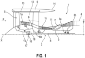
- FIG. 1 shows an axial sectional view of a turbomachine 1 of longitudinal axis X comprising a power transmission system and to which the invention applies.
- a turbomachine generally consists of several modules which are manufactured independently of each other and which are then assembled together so as to facilitate its assembly, its disassembly and its maintenance.
- the turbomachine 1 comprises, in a conventional manner, a fan S, a low pressure compressor 1a, a high pressure compressor 1b, an annular combustion chamber 2, a high pressure turbine 3a, a low pressure turbine 3b and an exhaust nozzle 4
- the high pressure compressor 1b and the high pressure turbine 3a are connected by a high pressure shaft 9 and with it form a high pressure body (HP).
- the low pressure compressor 1a and the low pressure turbine 3b are connected by a low pressure shaft 8 and with it form a low pressure body (LP).
- the fan S is enclosed by a fan casing 10 carried by an external nacelle 5.
- the fan S generates, from an air flow F entering the fan, a primary air flow which circulates in a primary vein 11 opening into the exhaust nozzle 4 and a secondary air flow which circulates in a secondary vein 13, around the primary vein 11, opening into an ejection nozzle 14.
- the fan S is rotated by a fan shaft 15 which is itself rotated by the low pressure shaft 8 via a speed reducer 16.
- the power transmission system includes the speed reducer 16.
- the latter is generally of the planetary or epicyclic type.
- the reducer 16 (or RGB) is positioned in the upstream part of the turbomachine in the present example.
- the reduction gear 16 could be arranged downstream of the turbomachine.
- a fixed structure comprising schematically, here, an upstream part 6a and a downstream part 6b which makes up the motor casing or stator 6 is arranged so as to form an enclosure 18 surrounding the reduction gear 16.
- a mist of lubricant reigns in the enclosure 18.
- This enclosure 18 is here closed upstream by seals at the level of an upstream bearing 19 allowing the crossing of the fan shaft 15, and downstream by seals at the level of the crossing of the low pressure shaft 8.
- the turbomachine 1 described is a double flow turbomachine 1 intended to be mounted on an aircraft.
- the invention can be applied to other types of turbomachines such as turboprops equipped with a single non-ducted propeller or a pair of counter-rotating, non-ducted propellers, and known by the English expression "open”. rotor”.
- the invention can be applied to other areas in which a speed reducer is necessary.
- the reducer 16 is connected to the low pressure shaft 8, for example via splines 7a.
- the low pressure shaft 8 drives a planetary pinion called the solar 20.
- the solar 20 whose axis of rotation coincides with that of the longitudinal axis X of the turbomachine, drives a series of satellite gears called satellites 21, which are equally distributed over the same diameter around the longitudinal axis of rotation for this type of application.
- All of the satellites 21 are held by a chassis called satellite carrier 22.
- Each satellite 21 rotates around its own axis Y, and meshes with the external crown 23.
- the speed reducer (or RGB) comprises a planetary gear train.
- Each satellite 21 is mounted to rotate freely using a bearing 24, for example of the rolling or hydrodynamic bearing type.
- a hydrodynamic bearing is supplied with “low” pressures (usually less than 10 bars). Rotating the bearing increases pressure on the oil wedge and separates the satellites and the bearings.
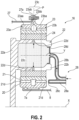
- Each level 24 (cf. figure 2 ) is mounted on one of the axes of the planet carrier 22 and all the axes are positioned relative to each other using one or more structural frames 22a of the planet carrier 22.
- Each satellite 21 meshes with external teeth of the solar 20 and the internal teeth of the external ring 23.
- the internal teeth of the external ring 23 can be straight (parallel to the longitudinal axis), helical or chevron.
- axles and the chassis can be separated into several parts.
- the half-fixing flange 25a of the front crown 23a and the half-fixing flange 25b of the rear crown 23b form the fixing flange 25 of the crown.
- the crown 23 is fixed to a crown holder by assembling the fixing flange 23c of the crown and the fixing flange 27a of the crown holder 27.
- the fixing is carried out here thanks to the fixing members.
- These fixing members can advantageously form a bolted assembly for example.
- the internal teeth of the external crown 23 can be in a chevron with helices which are separated along a median plane P.
- the first half-crown 23a comprises first helices and the second half-crown 23b includes second helices.
- the first and second helices of the internal teeth mesh with the external teeth of the satellites 21 which mesh with those of the solar 20.
- the arrows of the figure 2 describe the routing of the lubricant in the reducer 16.
- the lubricant arrives in the reducer 16 from the stator part 6 in a distributor 28 by different means which will not be specified in this view because they are specific to one or more types of architecture .
- the distributor 28 is separated into two parts generally each repeated with the same number of satellites.
- Injectors 28a have the function of lubricating the teeth and arms 28b have the function of lubricating the bearings.
- the lubricant is brought towards the injector 28a to exit through the end 28c in order to lubricate the teeth.
- the lubricant is also brought to the arm 28b and circulates via the supply port 28d of the bearing.
- the lubricant then circulates through the axis in one or more buffer zones 22c to then exit through the orifices 22d in order to lubricate the satellite bearings.
- radial is defined in relation to a radial axis Z perpendicular to the longitudinal axis X.
- the gearboxes can be composed of one or more meshing stages. This meshing is ensured in different ways such as by contact, by friction or even by magnetic fields. There are several types of contact meshing such as straight, helical or chevron teeth.
- stage a first series of meshing teeth of a pinion which meshes with a second series of complementary teeth of another pinion.
- the number of stages refers in particular to the satellites.
- the speed reducer illustrated on the figures 2 And 3 is of the one-stage (or single-stage) type which allows for a simple and compact architecture. It is the same toothing of a satellite which cooperates with the solar 20 and the crown 23.
- each satellite is double-decker and includes two distinct teeth which are located on different diameters.
- a first toothing of each satellite cooperates with the solar 20 and a second toothing of each satellite cooperates with the external crown 23.
- the first toothing which meshes with the solar 20 has a first average diameter and is located in a first median plane.
- the second toothing which meshes with the crown 23 has a second average diameter and is located in a second median plane P.
- the median planes are parallel to each other and perpendicular to the axis X.
- the second diameter is less than the first diameter.
- Each first and second tooth may comprise a single helix or may comprise two sets of chevron teeth.
- each satellite pinion 21 comprises a cylindrical body and an annular web extending substantially radially outwards from the middle of this body.
- the second toothing is separated into two series of chevron teeth which are located respectively on the axial ends of the body.
- the first toothing comprises two series of chevron teeth which are located at the external periphery of the web and which are separated from each other by an annular groove opening radially outwards relative to the Y axis.
- the teeth teeth are arranged symmetrically with respect to the plane passing through the middle of the teeth.
- Such a double-stage architecture makes it possible to improve the reduction ratios while maintaining a radial footprint and a reduced mass.
- the turbomachine 1 comprises for this a lubrication system 30 equipped, among other things, with the distributor 28 which injects the lubricant into the speed reducer 16.
- the turbomachine further comprises a lubricant circuit 32 connected on the one hand to the distributor 28 and on the other hand, to a supply tank 33. The lubricant passes through the different gears to be ejected by centrifugation radially towards the outside of the speed reducer 16.
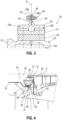
- the external crown 23 advantageously comprises ejection means 34 by which the lubricant is ejected outside the speed reducer 16.
- the lubricant is also injected at the level of the rotational guide bearings of the fan shaft 15.
- the ejection means 34 comprise one or more channels 35, as shown in the Figure 3 , which are for example regularly distributed at least on the circumference of the external crown 23. These channels 35 open on the one hand, on the internal periphery of the external crown 23 on which the internal teeth are defined (not shown). On the other hand, the channels 35 open onto the outer periphery 36 of the fixing flange 25 of the outer ring 23.
- the lubricant circulates from the inside of the outer ring 23 towards the outside of the latter via the channel(s) 35.
- the lubricant which circulates at the circumference of the outer ring 23 also evacuates between the fan shaft and the outer ring.
- a recovery device 40 completes the assembly and is designed to quickly recover and evacuate the lubricant ejected by centrifugal effect in the turbomachine and in particular in the enclosure 18.
- the recovery device 40 comprises a gutter 41 which is annular and which is centered on the longitudinal axis.
- the gutter 41 is arranged around the external crown 23.
- the gutter 41 is integral in rotation with the external crown 23.
- the gutter 41 comprises a radial tab 42 which is fixed to the radial fixing flange 25 of the external crown 23.
- the radial tab 42 is also annular.
- the radial tab 42 is fixed to the first half-flange 25a.
- the radial tab 42 can also be fixed on the radial ferrule of the fan shaft 15. The fixing is advantageously done with the same fixing members 26.
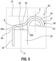
- the gutter 41 also includes a collection zone 43 or recovery chamber in which a large quantity of lubricant is received.
- the collection zone 43 is delimited by a retention wall 44 having a U- or C-shaped or even semi-circular shape (in an axial plane).
- the retention wall 44 is also annular and centered on the longitudinal axis X.
- the retention wall 44 is connected to the radial tab 42.
- the collection zone faces the external crown 23.
- the gutter 41 comprises a guide wall 45 which connects the retention wall 44 to the radial tab 42.
- the guide wall 45 is located between the radial tab 42 and the retention wall 44.
- the wall guide 45 is arranged facing the external periphery 36 of the radial fixing flange 25.
- the guide wall 45 faces the ejection means 34 of the lubricant.
- the collection zone 43 is offset axially relative to the median plane P of the outer ring 23, perpendicular to the longitudinal axis X.
- the collection zone 43 is located to the right of the radial fixing flange 25 of the outer ring 23.
- the collection zone 43 could be arranged opposite, or to the left of the radial fixing flange 25. This configuration makes it possible to limit the radial bulk.
- the arrangement of the collection zone 43 offset axially makes it possible to benefit from the axial space existing in this part of the enclosure 18.
- the bottom of the retention wall 44 is located radially outside the guide wall 45 and the external periphery 36 of the radial fixing flange 25.
- a first straight line 47 tangent to an external surface 46 of the gutter 41 passing by a point A located in a median plane of the retention wall 44 (in the plane of the figure 5 ) is arranged at a predetermined distance from a second straight line 48 tangent to the external periphery 36 of the radial fixing flange 25.
- the second tangent straight line 48 passes through a point B located in the median plane P.
- the wall of the gutter 41 has at least one point of inflection. Even more precisely, the gutter 41 has a point of inflection between the radial tab 42 and the guide wall 45.
- a first curved portion 49a comprising a point of inflection is located between the radial tab 42 and the guide wall 45. This first curved portion 49a is of concave shape facing the external crown 23.
- a second curved portion 49b comprising a point of inflection is located between the guide wall 45 and the retention wall 44. The second curved portion 49b is of convex shape facing the external crown 23.
- the guide wall has an inclination relative to the longitudinal axis X.
- the guide wall 45 is not too inclined (angle less than 90°) nor too flat (angle greater than 0°) relative to the longitudinal axis important would significantly distance the guide wall 45 from the ejection means 34 and the lubricant projections would not be redirected towards the collection zone 43 effectively.
- the angle of inclination of the direction of the guide wall 45 can be between 50° and 25° relative to the longitudinal axis X. In this way, in the event of projection, the lubricant can be received in collection area 43 without loss.
- the gutter 41 is advantageously made in one piece.
- the gutter can be produced by an additive manufacturing process, by conventional machining processes or by foundry.
- the gutter 41 is made of a metallic material or advantageously a metallic alloy.
- the assembly comprising the speed reducer also includes a device 50 for evacuating the lubricant outside the gutter 41 which is arranged in the turbomachine.
- This evacuation device 50 is advantageously intended to avoid possible overflows of lubricant from the gutter 41.
- the evacuation device 50 extends at least partly in the collection zone 43, i.e. in the gutter 41.
- the device d The evacuation 50 is configured so as to evacuate the lubricant located in the collection zone 43 towards an oil evacuation zone located outside the gutter.
- the evacuation device 50 is fixed to the stator 6 of the turbomachine.
- the evacuation device 50 is fixed to a casing of the turbomachine 1.
- the evacuation device 50 is separate from the speed reducer 16.
- the evacuation device 50 mounted integrally with the casing of the turbomachine . We then understand that such an arrangement makes it possible to evacuate the maximum amount of lubricant during the rotation of the gutter which collects the lubricant and to preserve the driving force of the lubricant which is in permanent rotation in the gutter.
- the evacuation device 50 comprises a first end arranged in the collection zone 43 and a second end arranged outside the collection zone 43.
- the evacuation device 50 comprises a pipe 51 of which at least a portion is installed in the gutter 41. More precisely, an inlet 52 of the pipe 51 is arranged or opens into the collection zone 43. The inlet 52 of the pipe forms the first end of the evacuation device.
- Pipe 51 includes an outlet 53 (cf. Figure 4 ) which is connected to a recovery circuit of the turbomachine. The outlet 53 of the pipe forms the second end of the evacuation device 50.
- the outlet 53 can be connected in this example to the supply tank 33. In this way, the lubricant is collected by the inlet 52 and is channeled to inside pipe 51 to outlet 53.
- output 53 is connected to a suction pump (not shown) of a recovery circuit.
- the outlet 53 is arranged freely in a storage tank arranged at the bottom of the enclosure. In this case the lubricant is sucked up with the rest of the lubricant from the front enclosure components (blower bearings, etc.) by a single suction pump.
- pipe 51 has a circular section.
- the pipe 51 has a semi-circular or U-shaped or C-shaped section.
- An opening 54 (at the inlet 52) opens into the interior of the pipe 51.
- FIG. 6 illustrates another embodiment of the gutter 41.
- the gutter 41 differs from the embodiment of the Figure 4 in that the collection zone 43 is located opposite the radial fixing flange 25. There is no axial offset of the collection zone 43.
- a large part of the lubricant which is ejected from the means ejection 34 at the level of the radial fixing flange 25, is received directly in the collection zone 43.
- Part of the lubricant can circulate on the internal surface of the guide wall 45 which extends along the radial axis or substantially along the radial axis.
- the guide wall 45 can be inclined relative to the radial axis at an angle of inclination of between 3° and 10°.
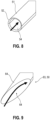
- the pipe 51 includes at least one point of inflection to facilitate the arrangement in relation to the gutter.
- the pipe comprises several curvatures which allow it to be arranged in relation to the rotating gutter 41 and the lubricant to be collected easily.
- the pipe 51 comprises portions extending in directions or dimensions different from each other.
- the pipe 51 comprises a first portion 55 which extends in a tangential direction relative to the internal surface of the gutter 41. This tangential direction is parallel to the circumferential direction of the gutter 41.
- the opening 54 of the pipe 51 at the inlet 52 faces the flow of lubricant. In this way, the lubricant can enter easily and directly into the pipe 51.
- the latter comprises a second portion 56 which extends generally (parallel or following an inclination of for example 5°) in the radial direction so as to be able to extract the lubricant of the gutter 41.
- the pipe 51 comprises a third portion 57 which extends generally (parallel or following an inclination of for example 5°) in a direction parallel to the longitudinal axis so as to axially offset the pipe of the gutter 41. This configuration also allows the rotation of the gutter 41 relative to the pipe 51 which is fixed.
- the pipe 51 comprises a fourth portion 58 which is connected to the supply tank 33.
- the part of the evacuation device 50 which extends into the gutter 41 has curvatures and has a half-moon shape.
- the latter forms a hollow 50a.
- the different portions of the pipe 51 are spaced a certain distance apart to avoid contact with the walls of the gutter and allow the gutter to rotate without obstacles.
- the lubricant is scooped out at a given point and the line is wide enough to avoid pressure losses. With this configuration it will be possible to recover and evacuate the desired flow to bring it to the recovery point at 6 o'clock.
- the lubricant can be evacuated to reservoir 33.
- At least one stiffening element 60 is provided to oppose the development of resonance of movement of the gutter 41 rotating during the operation of the turbomachine.
- the stiffening element 60 comprises an arm 61 which extends between the body of the pipe 51 and a stator casing of the turbomachine.
- the evacuation device 50 comprises an end which is arranged in the collection zone and which is beveled so as to evacuate the lubricant located in the zone collection 43 towards a lubricant evacuation zone located outside the gutter 41.
- the device 50 comprises a deflector 63.
- the deflector 63 is configured to divert the lubricant towards a predetermined location at the outside of the gutter 41 and outside the collection zone 43.
- the deflector 63 comprises a first portion 64 arranged in the collection zone 43.
- the first portion 64 forms the first end of the evacuation device 50.
- the deflector 63 comprises also a second portion (not shown) which is arranged outside the collection zone 43.
- the second portion forms the second end of the evacuation device.
- the second portion is oriented towards a specific location of the lubrication enclosure 18.
- Several deflectors 63 can be arranged in the collection zone of the gutter 41.
- the deflector 63 therefore advantageously presents a deflector surface 65 configured so as to evacuate the lubricant located in the collection zone 43 towards a lubricant evacuation zone located outside the gutter 41.
- the surface 65 is flat so that the lubricant can slide and/or circulate towards the outside of the gutter 41.
- the flat surface 65 is carried by the first portion 64.
- the lubricant is projected at the location precise in the lubrication chamber 18 so that the evacuation is controlled.
- the surface 65 of the deflector 63 is concave or convex depending on the strategies for collecting the lubricant in the enclosure of the speed reducer (and the shapes of the enclosure).
- the lubricant is oil.
- the evacuation device 50 is simple to implement and takes up little space in the enclosure.
- the device 20 makes it possible to evacuate the lubricant from the gutter in order to prevent the gutter 41 from overflowing anywhere in the enclosure.
Landscapes
- Engineering & Computer Science (AREA)
- Mechanical Engineering (AREA)
- General Engineering & Computer Science (AREA)
- Chemical & Material Sciences (AREA)
- Combustion & Propulsion (AREA)
- General Details Of Gearings (AREA)
Applications Claiming Priority (1)
| Application Number | Priority Date | Filing Date | Title |
|---|---|---|---|
| FR2300847A FR3145374A1 (fr) | 2023-01-30 | 2023-01-30 | Ensemble pour une turbomachine comprenant des moyens d’evacuation de lubrifiant et turbomachine equipee d’un tel ensemble |
Publications (2)
| Publication Number | Publication Date |
|---|---|
| EP4407149A1 true EP4407149A1 (de) | 2024-07-31 |
| EP4407149B1 EP4407149B1 (de) | 2025-10-22 |
Family
ID=85792172
Family Applications (1)
| Application Number | Title | Priority Date | Filing Date |
|---|---|---|---|
| EP24153084.9A Active EP4407149B1 (de) | 2023-01-30 | 2024-01-22 | Anordnung für eine strömungsmaschine mit schmiermittelabführungsmitteln und strömungsmaschine mit einer solchen anordnung |
Country Status (3)
| Country | Link |
|---|---|
| US (1) | US12509996B2 (de) |
| EP (1) | EP4407149B1 (de) |
| FR (1) | FR3145374A1 (de) |
Families Citing this family (1)
| Publication number | Priority date | Publication date | Assignee | Title |
|---|---|---|---|---|
| US20260063196A1 (en) * | 2024-08-28 | 2026-03-05 | General Electric Company | Gearbox assembly having a segmented scavenge gutter for a turbine engine |
Citations (6)
| Publication number | Priority date | Publication date | Assignee | Title |
|---|---|---|---|---|
| EP3473893A1 (de) | 2017-10-19 | 2019-04-24 | Ge Avio S.r.l. | Schmierfluidsammlung in einem getriebe eines gasturbinenmotors |
| US20190226575A1 (en) | 2018-01-25 | 2019-07-25 | Rolls-Royce Deutschland Ltd & Co Kg | Planetary gear mechanism and aircraft gas turbine with a planetary gear mechanism |
| EP3575562A1 (de) | 2018-05-28 | 2019-12-04 | Safran Aircraft Engines | Leistungsübertragungssystem, das eine schmierölrückgewinnungsvorrichtung umfasst, und mit einem solchen leistungsübertragungssystem ausgestattetes turbotriebwerk |
| US20200032710A1 (en) | 2018-07-26 | 2020-01-30 | Safran Aircraft Engines | Lubricating oil piping gutter of an aircraft turbomachine |
| FR3084427A1 (fr) * | 2018-07-26 | 2020-01-31 | Safran Transmission Systems | Dispositif de type reducteur mecanique pour une turbomachine |
| WO2020245529A1 (fr) | 2019-06-06 | 2020-12-10 | Safran Aircraft Engines | Reducteur planetaire pour une turbomachine d'aeronef |
-
2023
- 2023-01-30 FR FR2300847A patent/FR3145374A1/fr active Pending
-
2024
- 2024-01-22 EP EP24153084.9A patent/EP4407149B1/de active Active
- 2024-01-23 US US18/420,229 patent/US12509996B2/en active Active
Patent Citations (6)
| Publication number | Priority date | Publication date | Assignee | Title |
|---|---|---|---|---|
| EP3473893A1 (de) | 2017-10-19 | 2019-04-24 | Ge Avio S.r.l. | Schmierfluidsammlung in einem getriebe eines gasturbinenmotors |
| US20190226575A1 (en) | 2018-01-25 | 2019-07-25 | Rolls-Royce Deutschland Ltd & Co Kg | Planetary gear mechanism and aircraft gas turbine with a planetary gear mechanism |
| EP3575562A1 (de) | 2018-05-28 | 2019-12-04 | Safran Aircraft Engines | Leistungsübertragungssystem, das eine schmierölrückgewinnungsvorrichtung umfasst, und mit einem solchen leistungsübertragungssystem ausgestattetes turbotriebwerk |
| US20200032710A1 (en) | 2018-07-26 | 2020-01-30 | Safran Aircraft Engines | Lubricating oil piping gutter of an aircraft turbomachine |
| FR3084427A1 (fr) * | 2018-07-26 | 2020-01-31 | Safran Transmission Systems | Dispositif de type reducteur mecanique pour une turbomachine |
| WO2020245529A1 (fr) | 2019-06-06 | 2020-12-10 | Safran Aircraft Engines | Reducteur planetaire pour une turbomachine d'aeronef |
Also Published As
| Publication number | Publication date |
|---|---|
| EP4407149B1 (de) | 2025-10-22 |
| US20240254892A1 (en) | 2024-08-01 |
| FR3145374A1 (fr) | 2024-08-02 |
| US12509996B2 (en) | 2025-12-30 |
Similar Documents
| Publication | Publication Date | Title |
|---|---|---|
| EP3575562B1 (de) | Leistungsübertragungssystem, das eine schmierölrückgewinnungsvorrichtung umfasst, und mit einem solchen leistungsübertragungssystem ausgestattetes turbotriebwerk | |
| FR3047279B1 (fr) | Rouet de distribution a repartition axiale et reducteur a train epicycloidal ainsi equipe | |
| EP2834503B1 (de) | Vorrichtung zur rückgewinnung von schmieröl aus einem epizyklischen untersetzungsgetriebe | |
| EP3495692B1 (de) | Krone eines untersetzungsgetriebes mit planetensatz für strömungsmaschine | |
| EP3763971B1 (de) | Ölleitungsdeckel und mechanisches reduktionsgetriebe des triebwerks eines luftfahrzeugs, das einen solchen deckel umfasst | |
| EP3726097B1 (de) | Mechanisches reduktionsgetriebe für luftfahrzeug-turbotriebwerk | |
| EP4034797B1 (de) | Öldrossel zur notschmierung eines bauteils für ein flugzeugtriebwerk | |
| EP3956555B1 (de) | Reduktionsgetriebe einer turbomaschine | |
| FR3084427A1 (fr) | Dispositif de type reducteur mecanique pour une turbomachine | |
| FR2987417A1 (fr) | Dispositif de recuperation de l'huile de lubrification d'un reducteur epicycloidal. | |
| FR2987402A1 (fr) | Dispositif de lubrification d'un reducteur epicycloidal compatible d'un montage modulaire. | |
| FR3093550A1 (fr) | Reducteur mecanique de turbomachine d’aeronef | |
| EP4407149B1 (de) | Anordnung für eine strömungsmaschine mit schmiermittelabführungsmitteln und strömungsmaschine mit einer solchen anordnung | |
| EP4246018B1 (de) | Schmieröldeflektor, untersetzungsgetriebe mit solch einem deflektor und turbomaschine mit solch einem geschwindigkeitsminderer | |
| EP3699460B1 (de) | Solarelement für ein mechanisches reduktionsgetriebe für luftfahrzeug-turbotriebwerk | |
| EP4382775B1 (de) | Schmierölrückgewinnungsrinne für reduktionsgetriebe | |
| FR3145588A1 (fr) | Turbomachine comprenant un reducteur de vitesse ayant des brides de fixation accouplees par un accouplement a dentures. | |
| WO2025168906A1 (fr) | Couronne pour un reducteur mecanique d'une turbomachine d'aeronef | |
| FR3147614A1 (fr) | Ensemble pour un reducteur mecanique d’aeronef | |
| WO2025176957A1 (fr) | Dispositif d'alimentation en huile pour un reducteur mecanique d'une turbomachine d'aeronef | |
| WO2025022053A1 (fr) | Reducteur mecanique pour une turbomachine | |
| FR3167187A1 (fr) | Couronne mobile pour un reducteur mecanique d’aeronef |
Legal Events
| Date | Code | Title | Description |
|---|---|---|---|
| PUAI | Public reference made under article 153(3) epc to a published international application that has entered the european phase |
Free format text: ORIGINAL CODE: 0009012 |
|
| STAA | Information on the status of an ep patent application or granted ep patent |
Free format text: STATUS: REQUEST FOR EXAMINATION WAS MADE |
|
| 17P | Request for examination filed |
Effective date: 20240122 |
|
| AK | Designated contracting states |
Kind code of ref document: A1 Designated state(s): AL AT BE BG CH CY CZ DE DK EE ES FI FR GB GR HR HU IE IS IT LI LT LU LV MC ME MK MT NL NO PL PT RO RS SE SI SK SM TR |
|
| GRAP | Despatch of communication of intention to grant a patent |
Free format text: ORIGINAL CODE: EPIDOSNIGR1 |
|
| STAA | Information on the status of an ep patent application or granted ep patent |
Free format text: STATUS: GRANT OF PATENT IS INTENDED |
|
| INTG | Intention to grant announced |
Effective date: 20250530 |
|
| GRAS | Grant fee paid |
Free format text: ORIGINAL CODE: EPIDOSNIGR3 |
|
| GRAA | (expected) grant |
Free format text: ORIGINAL CODE: 0009210 |
|
| STAA | Information on the status of an ep patent application or granted ep patent |
Free format text: STATUS: THE PATENT HAS BEEN GRANTED |
|
| AK | Designated contracting states |
Kind code of ref document: B1 Designated state(s): AL AT BE BG CH CY CZ DE DK EE ES FI FR GB GR HR HU IE IS IT LI LT LU LV MC ME MK MT NL NO PL PT RO RS SE SI SK SM TR |
|
| REG | Reference to a national code |
Ref country code: CH Ref legal event code: F10 Free format text: ST27 STATUS EVENT CODE: U-0-0-F10-F00 (AS PROVIDED BY THE NATIONAL OFFICE) Effective date: 20251022 Ref country code: GB Ref legal event code: FG4D Free format text: NOT ENGLISH |
|
| REG | Reference to a national code |
Ref country code: DE Ref legal event code: R096 Ref document number: 602024000966 Country of ref document: DE |
|
| REG | Reference to a national code |
Ref country code: IE Ref legal event code: FG4D Free format text: LANGUAGE OF EP DOCUMENT: FRENCH |
|
| REG | Reference to a national code |
Ref country code: NL Ref legal event code: MP Effective date: 20251022 |
|
| PG25 | Lapsed in a contracting state [announced via postgrant information from national office to epo] |
Ref country code: NL Free format text: LAPSE BECAUSE OF FAILURE TO SUBMIT A TRANSLATION OF THE DESCRIPTION OR TO PAY THE FEE WITHIN THE PRESCRIBED TIME-LIMIT Effective date: 20251022 |
|
| PG25 | Lapsed in a contracting state [announced via postgrant information from national office to epo] |
Ref country code: ES Free format text: LAPSE BECAUSE OF FAILURE TO SUBMIT A TRANSLATION OF THE DESCRIPTION OR TO PAY THE FEE WITHIN THE PRESCRIBED TIME-LIMIT Effective date: 20251022 |
|
| REG | Reference to a national code |
Ref country code: LT Ref legal event code: MG9D |
|
| PG25 | Lapsed in a contracting state [announced via postgrant information from national office to epo] |
Ref country code: NO Free format text: LAPSE BECAUSE OF FAILURE TO SUBMIT A TRANSLATION OF THE DESCRIPTION OR TO PAY THE FEE WITHIN THE PRESCRIBED TIME-LIMIT Effective date: 20260122 |
|
| PGFP | Annual fee paid to national office [announced via postgrant information from national office to epo] |
Ref country code: DE Payment date: 20260120 Year of fee payment: 3 |
|
| PG25 | Lapsed in a contracting state [announced via postgrant information from national office to epo] |
Ref country code: HR Free format text: LAPSE BECAUSE OF FAILURE TO SUBMIT A TRANSLATION OF THE DESCRIPTION OR TO PAY THE FEE WITHIN THE PRESCRIBED TIME-LIMIT Effective date: 20251022 Ref country code: AT Free format text: LAPSE BECAUSE OF FAILURE TO SUBMIT A TRANSLATION OF THE DESCRIPTION OR TO PAY THE FEE WITHIN THE PRESCRIBED TIME-LIMIT Effective date: 20251022 Ref country code: FI Free format text: LAPSE BECAUSE OF FAILURE TO SUBMIT A TRANSLATION OF THE DESCRIPTION OR TO PAY THE FEE WITHIN THE PRESCRIBED TIME-LIMIT Effective date: 20251022 |
|
| PGFP | Annual fee paid to national office [announced via postgrant information from national office to epo] |
Ref country code: AT Payment date: 20260301 Year of fee payment: 3 |
|
| REG | Reference to a national code |
Ref country code: AT Ref legal event code: MK05 Ref document number: 1849297 Country of ref document: AT Kind code of ref document: T Effective date: 20251022 |
|
| PG25 | Lapsed in a contracting state [announced via postgrant information from national office to epo] |
Ref country code: RS Free format text: LAPSE BECAUSE OF FAILURE TO SUBMIT A TRANSLATION OF THE DESCRIPTION OR TO PAY THE FEE WITHIN THE PRESCRIBED TIME-LIMIT Effective date: 20260122 |
|
| PG25 | Lapsed in a contracting state [announced via postgrant information from national office to epo] |
Ref country code: IS Free format text: LAPSE BECAUSE OF FAILURE TO SUBMIT A TRANSLATION OF THE DESCRIPTION OR TO PAY THE FEE WITHIN THE PRESCRIBED TIME-LIMIT Effective date: 20260222 |
|
| PGFP | Annual fee paid to national office [announced via postgrant information from national office to epo] |
Ref country code: FR Payment date: 20260123 Year of fee payment: 3 |