EP4407152A1 - Module de refoulement d'huile destiné à alimenter un groupe d'un véhicule automobile - Google Patents
Module de refoulement d'huile destiné à alimenter un groupe d'un véhicule automobile Download PDFInfo
- Publication number
- EP4407152A1 EP4407152A1 EP24153760.4A EP24153760A EP4407152A1 EP 4407152 A1 EP4407152 A1 EP 4407152A1 EP 24153760 A EP24153760 A EP 24153760A EP 4407152 A1 EP4407152 A1 EP 4407152A1
- Authority
- EP
- European Patent Office
- Prior art keywords
- oil
- pump
- channel
- housing
- inlet
- Prior art date
- Legal status (The legal status is an assumption and is not a legal conclusion. Google has not performed a legal analysis and makes no representation as to the accuracy of the status listed.)
- Pending
Links
Images



Classifications
-
- F—MECHANICAL ENGINEERING; LIGHTING; HEATING; WEAPONS; BLASTING
- F01—MACHINES OR ENGINES IN GENERAL; ENGINE PLANTS IN GENERAL; STEAM ENGINES
- F01M—LUBRICATING OF MACHINES OR ENGINES IN GENERAL; LUBRICATING INTERNAL COMBUSTION ENGINES; CRANKCASE VENTILATING
- F01M11/00—Component parts, details or accessories, not provided for in, or of interest apart from, groups F01M1/00 - F01M9/00
- F01M11/0004—Oilsumps
-
- F—MECHANICAL ENGINEERING; LIGHTING; HEATING; WEAPONS; BLASTING
- F01—MACHINES OR ENGINES IN GENERAL; ENGINE PLANTS IN GENERAL; STEAM ENGINES
- F01M—LUBRICATING OF MACHINES OR ENGINES IN GENERAL; LUBRICATING INTERNAL COMBUSTION ENGINES; CRANKCASE VENTILATING
- F01M1/00—Pressure lubrication
- F01M1/12—Closed-circuit lubricating systems not provided for in groups F01M1/02 - F01M1/10
-
- F—MECHANICAL ENGINEERING; LIGHTING; HEATING; WEAPONS; BLASTING
- F16—ENGINEERING ELEMENTS AND UNITS; GENERAL MEASURES FOR PRODUCING AND MAINTAINING EFFECTIVE FUNCTIONING OF MACHINES OR INSTALLATIONS; THERMAL INSULATION IN GENERAL
- F16H—GEARING
- F16H57/00—General details of gearing
- F16H57/04—Features relating to lubrication or cooling or heating
- F16H57/045—Lubricant storage reservoirs, e.g. reservoirs in addition to a gear sump for collecting lubricant in the upper part of a gear case
-
- F—MECHANICAL ENGINEERING; LIGHTING; HEATING; WEAPONS; BLASTING
- F01—MACHINES OR ENGINES IN GENERAL; ENGINE PLANTS IN GENERAL; STEAM ENGINES
- F01M—LUBRICATING OF MACHINES OR ENGINES IN GENERAL; LUBRICATING INTERNAL COMBUSTION ENGINES; CRANKCASE VENTILATING
- F01M1/00—Pressure lubrication
- F01M1/12—Closed-circuit lubricating systems not provided for in groups F01M1/02 - F01M1/10
- F01M2001/126—Dry-sumps
-
- F—MECHANICAL ENGINEERING; LIGHTING; HEATING; WEAPONS; BLASTING
- F01—MACHINES OR ENGINES IN GENERAL; ENGINE PLANTS IN GENERAL; STEAM ENGINES
- F01M—LUBRICATING OF MACHINES OR ENGINES IN GENERAL; LUBRICATING INTERNAL COMBUSTION ENGINES; CRANKCASE VENTILATING
- F01M11/00—Component parts, details or accessories, not provided for in, or of interest apart from, groups F01M1/00 - F01M9/00
- F01M11/0004—Oilsumps
- F01M2011/0025—Oilsumps with heat exchangers
-
- F—MECHANICAL ENGINEERING; LIGHTING; HEATING; WEAPONS; BLASTING
- F01—MACHINES OR ENGINES IN GENERAL; ENGINE PLANTS IN GENERAL; STEAM ENGINES
- F01M—LUBRICATING OF MACHINES OR ENGINES IN GENERAL; LUBRICATING INTERNAL COMBUSTION ENGINES; CRANKCASE VENTILATING
- F01M11/00—Component parts, details or accessories, not provided for in, or of interest apart from, groups F01M1/00 - F01M9/00
- F01M11/0004—Oilsumps
- F01M2011/0029—Oilsumps with oil filters
-
- F—MECHANICAL ENGINEERING; LIGHTING; HEATING; WEAPONS; BLASTING
- F01—MACHINES OR ENGINES IN GENERAL; ENGINE PLANTS IN GENERAL; STEAM ENGINES
- F01M—LUBRICATING OF MACHINES OR ENGINES IN GENERAL; LUBRICATING INTERNAL COMBUSTION ENGINES; CRANKCASE VENTILATING
- F01M11/00—Component parts, details or accessories, not provided for in, or of interest apart from, groups F01M1/00 - F01M9/00
- F01M11/0004—Oilsumps
- F01M2011/0033—Oilsumps with special means for guiding the return of oil into the sump
-
- F—MECHANICAL ENGINEERING; LIGHTING; HEATING; WEAPONS; BLASTING
- F01—MACHINES OR ENGINES IN GENERAL; ENGINE PLANTS IN GENERAL; STEAM ENGINES
- F01M—LUBRICATING OF MACHINES OR ENGINES IN GENERAL; LUBRICATING INTERNAL COMBUSTION ENGINES; CRANKCASE VENTILATING
- F01M11/00—Component parts, details or accessories, not provided for in, or of interest apart from, groups F01M1/00 - F01M9/00
- F01M11/0004—Oilsumps
- F01M2011/0066—Oilsumps with passages in the wall, e.g. for axles or fluid passages
-
- F—MECHANICAL ENGINEERING; LIGHTING; HEATING; WEAPONS; BLASTING
- F01—MACHINES OR ENGINES IN GENERAL; ENGINE PLANTS IN GENERAL; STEAM ENGINES
- F01M—LUBRICATING OF MACHINES OR ENGINES IN GENERAL; LUBRICATING INTERNAL COMBUSTION ENGINES; CRANKCASE VENTILATING
- F01M11/00—Component parts, details or accessories, not provided for in, or of interest apart from, groups F01M1/00 - F01M9/00
- F01M11/0004—Oilsumps
- F01M2011/007—Oil pickup tube to oil pump, e.g. strainer
-
- F—MECHANICAL ENGINEERING; LIGHTING; HEATING; WEAPONS; BLASTING
- F01—MACHINES OR ENGINES IN GENERAL; ENGINE PLANTS IN GENERAL; STEAM ENGINES
- F01M—LUBRICATING OF MACHINES OR ENGINES IN GENERAL; LUBRICATING INTERNAL COMBUSTION ENGINES; CRANKCASE VENTILATING
- F01M11/00—Component parts, details or accessories, not provided for in, or of interest apart from, groups F01M1/00 - F01M9/00
- F01M11/0004—Oilsumps
- F01M2011/0079—Oilsumps with the oil pump integrated or fixed to sump
-
- F—MECHANICAL ENGINEERING; LIGHTING; HEATING; WEAPONS; BLASTING
- F01—MACHINES OR ENGINES IN GENERAL; ENGINE PLANTS IN GENERAL; STEAM ENGINES
- F01M—LUBRICATING OF MACHINES OR ENGINES IN GENERAL; LUBRICATING INTERNAL COMBUSTION ENGINES; CRANKCASE VENTILATING
- F01M11/00—Component parts, details or accessories, not provided for in, or of interest apart from, groups F01M1/00 - F01M9/00
- F01M11/0004—Oilsumps
- F01M2011/0087—Sump being made of different parts
Definitions
- the invention relates to an oil delivery module for supplying an assembly (machine assembly) for a motor vehicle, for example one that is electrically or fully electrically powered.
- An oil pan of the oil delivery module has, for example, a multi-part housing, such as a three-part housing.
- the oil pan can be designed, for example, as an oil filter module and form an oil filter receptacle, which can, for example, be an integral part of the housing or a housing part of the oil pan.
- the oil pan can be part of the oil delivery module, which is designed to supply at least one machine assembly with oil, in particular to supply an (electric) motor and/or a transmission of a motor vehicle with oil.
- the machine assembly can, for example, be a structural unit or a combination of electric motor and transmission, which is arranged on a drive shaft and/or a housing of the electric motor.
- the oil is used to lubricate and/or cool the machine assembly.
- the oil pan comprises a housing with an oil receiving space for storing the oil, which can also be referred to herein as fluid.
- the oil delivery module can have at least one pump for conveying the fluid to the machine unit and a heat exchanger.
- Fluid delivery systems for supplying a machine unit, in particular an engine or a transmission of a motor vehicle, with fluid are known from the prior art.
- Such systems are based on the concept of pressure circulation lubrication, in particular wet sump lubrication, whereby fluid is delivered to the fluid consumers, i.e. the points to be lubricated and/or cooled, by means of a pump.
- wet sump lubrication the oil is collected as it drains from the machine unit in a reservoir, in particular an oil pan, which is arranged underneath the machine unit. The oil is pumped out of the oil pan by means of the pump and fed back to the machine unit. In this way, an oil circuit is created.
- the invention is based on an oil delivery module that is designed to supply a unit for a motor vehicle.
- the oil delivery module has an oil pan, a pump, in particular with a drive, and a heat exchanger.
- the pump can preferably be arranged not only functionally, but also structurally, i.e. in geometric terms, between the heat exchanger and the oil pan. This results in an advantageously compact design in which the components are combined to form a relatively flat oil delivery module, whereby the oil delivery module or its oil pan can be arranged below the unit.
- the oil pan comprises a housing that encloses an oil receiving space for storing oil.
- the housing comprises a housing frame, a housing base and a housing cover, which are, for example, separate parts that can be welded together in a fluid-tight manner.
- one of the housing base and housing cover can be formed integrally with the housing frame and the other of the housing base and housing cover can be a separate part or closure part that can be joined, in particular welded, to the housing frame.
- the housing frame is arranged between the housing cover and the housing base.
- the housing frame can form a circumferential side wall that encloses the oil receiving space on the circumference.
- the side wall can have several side wall sections. One of the side wall sections can be designed as a connection wall on which the pump is arranged.
- One or more connections for the fluid-communicating connection of the pump to the oil pan can be formed on the connection wall and/or the pump can be attached.
- the pump can be provided with one or more several screw bolts, each of which is screwed to an internal thread of the connecting wall.
- the pump can have a first pump outlet on a first side facing the heat exchanger and a first pump inlet on a second side facing the oil pan, in particular the connection wall, which is opposite the first side.
- the pump can have a first pump inlet, via which oil can be pumped into the pump, in particular from the oil pan, and a first pump outlet, via which oil can be pumped out of the pump, in particular into the heat exchanger, wherein the first pump inlet, in particular an inlet channel center axis of the first pump inlet, and the first pump outlet, in particular an outlet channel center axis of the first pump outlet, are arranged in a line and/or perpendicular to a drive shaft of the pump.
- the first pump inlet and the first pump outlet can be arranged in a line such that the inlet channel center axis is coincident with the outlet channel center axis, i.e. is aligned with the outlet channel center axis.
- the inlet and outlet channel center axes can alternatively be parallel to one another or arranged perpendicular to the drive shaft of the pump.
- the described arrangement of the first pump inlet and the first pump outlet allows the oil pan, the heat exchanger and the pump to be assembled or mounted compactly and easily to form the oil delivery module.
- a further advantage of the aligned arrangement is a reduced pressure loss in the oil flowing through the first flow in particular, which reduces the energy consumption of the pump and increases efficiency.
- the connection wall can have a first pump inlet connection, for example in the form of a pipe or nozzle, for the first pump inlet.
- the first pump inlet connection can be connected to the first pump inlet, in particular can be plugged into the first pump inlet.
- the heat exchanger can have a first pump outlet connection for the first pump outlet, for example in the form of a pipe or nozzle.
- the first pump outlet can be connected to the first pump outlet connection, in particular can be plugged into the first pump outlet connection.
- the oil delivery module is configured in such a way that oil can be delivered from the oil receiving space into the heat exchanger by means of the pump, for example with a first flow of a multi-flow, in particular double-flow pump. In principle, this function can also be achieved with a pump with only one flow.
- the first for example, a tubular or nozzle-shaped pump inlet connection (12) and/or the first pump inlet (3c) form an inlet channel longitudinal axis and the first, for example, tubular or nozzle-shaped pump outlet (3a) and/or the first pump outlet connection (4c) form an outlet channel longitudinal axis, and wherein the inlet channel longitudinal axis and the outlet channel longitudinal axis are arranged parallel to one another or in alignment with one another.
- the pump can, for example, have a first pump set for the first flow and a second pump set for the second flow, which are arranged offset from one another along the drive shaft, for example.
- the first and/or second pump set can, for example, be designed as an internal gear pump, or alternatively as a vane pump.
- the first inlet connection and the first outlet connection can preferably be arranged between the first pump set and the second pump set with respect to the longitudinal direction of the drive shaft, wherein it is further preferred that only the first pump set can pump oil into the pump via the first pump inlet and out of the pump via the first pump outlet.
- the second pump set can pump oil into the pump via a second pump inlet and out of the pump via a second pump outlet.
- An inlet opening can be formed between the first pump set and an inlet channel running from the first inlet connection along the inlet channel central axis, which connects the inlet channel to a suction region of the first pump insert.
- An outlet opening can be formed between the first pump set and an outlet channel running from the first outlet connection along the outlet channel central axis, which connects the outlet channel to a pressure region of the first pump set.
- the inlet channel and the outlet channel and/or the inlet channel central axis and the outlet channel central axis can be arranged between the first and second pump sets with respect to the longitudinal direction of the drive shaft.
- the oil pumped into the heat exchanger can be pumped, for example, via an oil filter to the unit to be supplied and/or back into the oil pan, in particular into a channel of the oil pan.
- the oil pan, in particular the housing cover can have at least one supply outlet on the top, into which the channel opens and via which the oil pumped via the first flow is delivered to the unit to be supplied.
- the first flow advantageously serves to guide the oil stored in a receiving space of the oil pan via the heat exchanger and optionally the oil filter to the unit to be supplied.
- the oil pan in particular one of its side walls, preferably the connecting wall, can comprise an oil filter receptacle for receiving an oil filter.
- the oil filter receptacle is preferably formed integrally by the housing frame, in particular the connecting wall.
- the oil filter receptacle can be connected on the one hand to the oil channel of the oil feed module and on the other hand to the heat exchanger, whereby oil, in particular oil from the first flow, can be conveyed from the heat exchanger via the oil filter receptacle and the oil filter into the channel.
- the oil filter can be designed as an oil filter cartridge and inserted into the oil filter receptacle.
- the oil filter receptacle can have a peripheral wall formed by the oil pan, in particular the housing frame or the connecting wall, which surrounds the oil filter over its circumference and is closed at the front by a cover formed by the heat exchanger.
- the cover can in particular close the front side facing away from the connecting wall and have a passage through which oil conveyed from the heat exchanger is conveyed through the cover into the oil filter receptacle.
- the oil filter holder can have a passage on the end face opposite the cover, which is formed, for example, by the housing frame or the connecting wall, which opens into the channel that opens into the at least one supply outlet.
- the oil filter is arranged in such a way that the oil conveyed through the passage of the cover into the oil filter holder flows through the oil filter and is conveyed out of the oil filter holder through the passage that opens into the channel.
- the peripheral wall can have a central axis that is perpendicular or approximately perpendicular in relation to the connecting wall and/or a drive shaft of the pump.
- the peripheral wall and/or the oil filter are cylindrical or approximately cylindrical.
- the pump can be driven by a drive arranged on it, in particular designed as an electric motor.
- the pump and the drive can form a drive-pump unit.
- the drive-pump unit, in particular the drive and/or the pump can be arranged between the connection wall of the housing frame and the heat exchanger. This achieves a space-saving arrangement.
- the pump can be positioned between the oil filter holder, which preferably protrudes from the connection wall or the part of the connection wall that forms the at least one connection for the pump, and the drive. This also achieves a space-saving arrangement.
- the pump or the drive pump unit can be attached to the side wall of the pan, for example by means of several screw bolts.
- the heat exchanger can be attached to the pump or the drive pump unit and to the housing frame, in particular the oil filter holder of the oil pan, for example by means of one or more screw bolts that are screwed into an internal thread of the pump and/or the oil filter holder. This makes it easy to install the oil feed module.
- connection wall can have a second, in particular tubular or nozzle-shaped, pump inlet connection and a second, in particular tubular or nozzle-shaped, pump outlet connection and the pump can have a second pump inlet which is connected to the second pump inlet connection and a second pump outlet which is connected to the second pump outlet connection.
- the second pump inlet connection can be plugged into the second pump inlet and the second pump outlet connection can be plugged into the second pump outlet.
- the pump is configured such that it can pump oil from the second pump inlet or second pump inlet connection to the second pump outlet or second pump outlet connection, in particular by means of a second flow which is separated from the first flow in the pump.
- the function of the second flow can be achieved by means of a separate pump, but a two-flow pump is preferred in favor of a compact design.
- the oil pan in particular the housing cover of the oil pan, can have at least one return inlet designed for returning oil from the unit.
- the oil pan, in particular the housing frame and/or the housing cover can have an oil channel that connects the return inlet to the second pump inlet connection.
- the oil pan, in particular the housing frame and/or the housing cover can have a channel that connects the pump outlet connection to the oil receiving space, for example a first section of the oil receiving space. This allows the oil delivery module, in particular the oil pan and the pump, to deliver oil from the return inlet via the pump into the oil receiving space. This allows returned oil to be delivered in a targeted manner to a certain location in the oil receiving space, for example into the first section of the oil receiving space.
- oil can be pumped from the oil pan's receiving space with a first flow of the pump via the heat exchanger and the oil filter to at least one supply outlet of the oil pan to supply the unit with oil.
- oil can be pumped from the oil pan's return inlet to a desired location in the receiving space with the pump's second flow.
- a drive shaft of the pump and/or the drive can be arranged within a projection of the connection wall, in particular in the direction in which the at least one connection for the pump protrudes, and/or between planes spanned by the housing cover and the housing base.
- the drive shaft can be parallel to the housing cover or the housing base of the oil pan. In the installation position of the oil feed module provided in the vehicle, the drive shaft can run horizontally in relation to the earth's gravitational field.
- the housing cover can be arranged on the upward-facing front side of the housing frame and/or close off the oil receiving space from above.
- the housing base can be arranged on the downward-facing front side of the housing frame and/or close off the oil receiving space from below.
- the housing cover can be arranged on the front side of the housing frame that faces a unit that is supplied with oil from the oil filter module.
- the housing base can be arranged on the front side of the housing frame that faces away from a unit that is supplied with oil from the oil pan.
- “Top” refers to the installation position intended for the operation of the oil pan and points away from the center of the earth.
- Bottom refers to the installation position intended for the operation of the oil pan and points towards the center of the earth.
- the oil pan or at least its housing can be designed flat, in particular for a motor vehicle with a low center of gravity, for example an electric or fully electric vehicle, as can be the case with sports cars.
- Flat means that the height of the oil pan or housing, which extends from the housing base over the housing frame to the housing cover, is significantly smaller than the length and width extending transversely to it.
- the housing cover and the housing base can be arranged parallel or diagonally to each other.
- the surrounding side wall of the housing frame can have several side wall sections, which together form a form an approximately rectangular shape.
- Two opposite side wall sections can be of the same height, for example, for a parallel arrangement of the housing cover and housing base, or of different heights for an inclined arrangement of the housing cover and housing base.
- the higher of these side wall sections can be the connecting wall.
- Two further side wall sections can connect the two opposite side wall sections.
- the two further side wall sections can be wedge-shaped for the inclined arrangement of the housing base and housing cover.
- the housing cover can be joined to the housing frame by means of a joint, such as a screw connection or preferably a material-tight joint, in particular by gluing or welding.
- the housing base can be joined to the housing frame by means of a joint, such as a screw connection or preferably a material-tight joint, in particular by gluing or welding.
- the parts of the housing can be made of metal.
- the housing parts are made of plastic or at least predominantly of plastic. This means that at least one of the housing frame, housing base and housing cover is made of a plastic or predominantly of a plastic.
- the housing base, the housing cover and the housing frame can be separate components that are joined together in a fluid-tight or oil-tight manner in the assembled or joined state, in particular welded, for example to seal the oil receiving space from the outside.
- the housing frame as such can form one or more oil channels.
- the housing frame together with the housing base and/or the housing cover can form one or more oil channels.
- the oil channel(s) can serve or be configured to supply oil to the unit via the oil pan and/or to drain oil from the unit.
- the housing frame can be joined to the housing cover and/or the housing base in such a way, for example by means of gluing or welding (i.e. material-locking joints), that the oil channel(s) are sealed to the outside and/or to the oil receiving space by the weld or glue seam, in particular in an oil-tight or fluid-tight manner.
- This allows separate seals arranged between the housing frame and the housing cover or between the housing frame and the housing base, such as Flat seals can be saved. In principle, however, designs with such separate seals are also possible.
- the oil pan in particular the housing or the housing frame, can have or integrally form an oil filter holder that is configured to hold an oil filter to form an oil filter module.
- the oil filter holder which is pot-shaped for example, can have a peripheral wall and an end wall.
- the oil filter or an oil filter insert i.e. an oil filter cartridge
- the oil filter can be or be inserted into the oil filter holder, whereby the oil filter holder can form the housing for the oil filter insert.
- Designs are therefore possible in which the oil filter has an oil filter housing and an oil filter insert arranged therein and is inserted into the oil filter holder, and alternatively in which the oil filter essentially only has the oil filter insert and the oil filter holder forms the oil filter housing.
- the latter design has the advantage that a separate housing for the oil filter insert and thus weight, installation space and costs can be saved.
- the oil filter holder can be a component separate from the housing, which is, for example, attached to the housing or housing frame or at least connected in a fluid-communicating manner to the oil pan or an oil channel of the oil pan.
- one of the housing parts, in particular the housing frame, forms the oil filter holder integrally.
- the oil pan also has an intake channel that extends into the oil receiving space, which is particularly enclosed by the housing, and has an opening through which oil can be conveyed from the oil receiving space through the intake channel.
- the intake channel can be arranged entirely or completely within the housing or in the oil receiving space.
- the intake channel can be connected to the suction side of a pump, so that oil can be sucked from the oil receiving space through the intake channel to the pump.
- the opening is arranged so that it extends into the oil sump stored in the oil receiving space.
- the oil pan in particular the housing or its housing frame, can have a pump inlet connection that is or can be connected in a fluid-communicating manner to the inlet of a feed pump.
- the intake channel is connected in a fluid-communicating manner to the pump inlet connection.
- the intake channel can be formed by the housing of the oil pan or as a separate part thereof.
- the intake channel - which in embodiments can be arranged entirely or completely within the housing or in the oil receiving space - can be formed by a tubular body, i.e. an intake pipe, which is inserted into a channel receptacle formed by the housing, in particular the housing frame.
- the channel receptacle can be formed integrally with the housing, in particular the housing frame.
- the housing, in particular the housing frame can form a channel or passage that connects the channel receptacle and the pump inlet connection.
- a seal can be arranged to seal a gap or sealing gap formed between the intake pipe and the channel receptacle.
- the housing frame can form the intake channel or at least a part of the intake channel, in particular integrally.
- the intake channel can have a section that is open in the longitudinal direction of the channel and is formed by the housing or the housing frame. The open section can be closed by the housing cover or a separate cover to form a closed channel cross-section of the intake channel.
- the intake channel having a section that is open in the longitudinal direction of the channel can be an integral part of the housing, in particular of one of the housing parts, such as the housing frame or the housing base.
- the intake channel can be formed entirely by the housing frame, i.e. be an integral part of the housing frame.
- the oil channel or one of the oil channels can be connected to the oil filter holder in a fluid-communicating manner or can open into the oil filter holder. This makes it possible for the oil, which has been filtered from impurities by an oil filter mounted in the oil filter holder, to be conveyed through the oil channel, in particular to a fluid consumer or the unit to which the oil is to be supplied.
- the oil pan such as its housing, for example the housing frame and/or preferably the housing cover, can have at least one supply outlet designed to supply oil to the unit.
- the oil channel or one of the oil channels can fluidly communicate with the oil filter holder and the at least one supply outlet. connect so that oil can be conveyed from the oil filter holder to the at least one supply outlet through the oil channel.
- the supply outlet can point upwards or towards the unit.
- the supply outlet can be arranged on the top of the housing, in particular the housing cover.
- the oil pan can have a single, two, three or even more such supply outlets.
- one supply outlet can be provided for supplying the electric motor and an additional supply outlet for supplying the transmission with oil.
- the oil pan can have one or more return inlets for returning oil from the unit to the oil pan.
- the oil dripping or flowing off the unit can be returned to the oil pan by gravity via the at least one return inlet.
- the oil from the unit can be led via the return inlet directly, in particular due to gravity or without having to go via a pump, into the oil pan or the oil receiving space or via the oil channel or one of the several oil channels formed by the housing frame or by the housing frame together with the housing cover.
- the oil pan can have one or more return inlets for returning oil from the unit to the oil pan and a, in particular additional or second, pump inlet connection for conveying fluid from the return inlet or one of the return inlets to a pump.
- the oil channel or one of the oil channels can connect the return inlet or one of the return inlets to the pump inlet connection so that oil can be conveyed through the oil channel from the return inlet or one of the return inlets to the pump inlet connection.
- the oil conveyed from the return inlet via the oil channel and the pump inlet connection can be conveyed back into the oil pan, in particular into the oil receiving space, via the pump.
- the oil channel through which the pump conveys the oil into the oil receiving space can be designed such that it conveys the oil to a desired location in the oil receiving space, such as e.g. B. in the area of the opening of the intake channel or in a section of the oil receiving space divided into several sections, such as the section in which the opening of the intake channel is arranged or into which the intake channel opens.
- the oil channel connecting the pump outlet connection to the oil receiving space can open into the oil receiving space or said section of the oil receiving space.
- the oil channel or one of the oil channels can connect the pump outlet connection which is connected to an outlet of the pump or can be connected can be connected to the oil receiving chamber, so that oil can be conveyed from the pump outlet connection into the oil receiving chamber, in particular the said section, through the oil channel.
- the oil pan can alternatively or additionally have one or more return inlets for the direct return of oil from the unit into the oil pan.
- the housing such as the housing cover, can have the one or more return inlets.
- the return inlet or one of the return inlets can open, in particular directly, into the oil receiving space, so that oil can flow from the return inlet directly into the oil receiving space, in particular into a first section or a second section of the oil receiving space.
- the first section can be the section into which the intake channel opens or in which the opening of the intake channel is arranged.
- the second section can be a section of the oil receiving space separated from the first section, for example by a partition wall.
- a return inlet can be provided via which oil from the unit can be conveyed directly into the first section and/or a return inlet can be provided via which oil from the unit can be conveyed directly into the second section.
- the partition that separates the two sections can have a passage that connects the two sections to one another in a fluid-communicating manner.
- the passage forms a bottleneck so that oil can flow from one section to the other in a throttled manner. This can advantageously ensure that oil from the first section can in principle flow into the second section, but only in a throttled manner, thus reducing the risk of suddenly no oil being available at the opening of the intake duct when cornering. Because the flow of oil from the first section to the second section is throttled, it takes longer for the oil to reach the second section compared to designs in which there is no partition and the oil can flow unthrottled from the first to the second section. Overfilling of the first section is also avoided because excess oil can flow through the passage into the second section.
- the passage also allows oil from the second section to flow into the first section so that oil from the second section is also available in the first section if there is a shortage of oil there.
- the oil pan or the housing cover can have a return inlet for returning oil from the unit to the receiving space or the first section of the receiving space, wherein the opening of the intake channel is arranged below or in a projection of the return inlet.
- a deflector can be arranged between the return inlet and the opening, which is configured such that oil flowing from the return inlet into the oil pan flows or flows against the deflector. The deflector thus prevents oil flowing from the return inlet into the oil receiving space from flowing directly into the opening.
- the deflector can be collar-shaped, dome-shaped or plate-shaped, for example. Other shapes are also possible, as long as direct flow into the opening is prevented.
- the advantage of preventing the flow directly to the opening is that the oil flowing back from the unit is calmed by the detour via the deflector. This can reduce the effect of the oil flowing back introducing excessive air and turbulence into the oil in the first section. This can improve the suction of the oil into the intake channel or reduce the proportion of air in the oil being sucked in.
- a strainer can be arranged in the or in at least one or in each of the return inlets for returning oil from the unit to the oil pan, which strainer is configured such that the oil returned from the unit to the oil pan flows through it.
- the strainer ensures that any impurities that may come loose from the unit do not reach the oil pan.
- the strainer can be used to calm the returning oil of foam particles or turbulence, in particular as an alternative or in addition to an optionally provided deflector.
- the one oil channel or the several oil channels that the housing frame forms together with the housing cover and/or the housing base can, for example, be arranged between the housing frame and the housing cover or the housing frame and the housing base.
- At least one of the housing frame and the housing cover can have at least one channel section on its side facing the housing cover or housing frame, which can be designed in a channel shape, for example.
- the at least one channel section can cover the one or more channels from the other of the housing cover or housing frame, in particular from at least one corresponding, for example, channel-shaped channel section, to form a closed channel cross-section.
- the housing frame and the housing cover can together form the at least one oil channel.
- At least one of the housing frame and the housing base can have at least one channel section on its side facing the housing base or housing frame, which can be designed in a channel shape, for example.
- the at least one channel section can cover the one or more channels from the other of the housing base or housing frame, in particular from at least one corresponding, for example channel-shaped, channel section, to form a closed channel cross-section.
- the housing frame and the housing base can together form the at least one oil channel.
- the oil channel is formed by the housing frame and the housing cover and/or the housing base simplifies the manufacture of the housing.
- the channel-shaped section can be provided during the molding, in particular during the primary molding such as injection molding, of the housing frame or the housing cover or the housing base.
- the oil channel or channels can be completed by joining the housing frame with the housing cover and the housing base. Manufacturing the oil channels, for example by machining or post-processing, can thus be avoided or at least the amount of such post-processing can be reduced.
- only one or several oil channels can be provided, which connect the at least one supply outlet or several supply outlets to the oil filter receptacle in a fluid-communicating manner.
- one or several oil channels can be provided for connecting the return inlet or several return inlets to the pump inlet connection.
- the oil channels mentioned can be formed in the manner described herein by covering a channel-shaped section.
- the housing for example the housing frame, can have or form an integral sensor receptacle to which a peripheral device, in particular a temperature sensor, is attached.
- a peripheral device in particular a temperature sensor
- the temperature sensor can be plugged into or snapped into the sensor receptacle.
- the sensor receptacle or the peripheral device can be configured such that a parameter, in particular the temperature, of the oil in the oil channel or in one of the oil channels can be detected with the peripheral device.
- the peripheral device can extend into the oil channel or one of the oil channels.
- the temperature sensor preferably extends into the oil channel connecting the oil filter receptacle and a supply outlet, in particular between the oil filter receptacle and the supply outlet.
- the at least one pump can be designed with two flows, with one flow serving to convey oil from the oil pan and supply it to the machine unit, and a second flow serving to convey oil returned from the unit to a specific location in the oil receiving space.
- a pump inlet in particular a first pump inlet, can be connected in a fluid-communicating manner to the intake channel, in particular the (first) pump inlet connection of the housing of the oil pan, so that oil can be conveyed from the oil pan into the pump via the intake channel.
- a (first) pump outlet of the pump can be connected in a fluid-communicating manner to the oil pan or its (first) oil channel, so that oil can be conveyed from the pump into the oil channel of the oil pan.
- oil can be conveyed via the (first) pump outlet of the pump via the oil channel to the at least one supply outlet for supplying the unit with oil.
- the oil filter receptacle and the oil filter can, for example, be arranged between the (first) pump outlet and the oil channel of the oil filter module. Accordingly, the (first) pump outlet of the pump is connected to the oil filter receptacle in a fluid-communicating manner.
- a heat exchanger can be provided in order to be able to remove the heat released by the unit into the returned oil from the fluid circuit.
- the heat exchanger can be arranged between the (first) pump outlet and the oil pan or the oil filter receptacle of the oil pan.
- the heat exchanger is configured in such a way that the oil conveyed from the first pump outlet to the oil filter module can flow through it. Thermal energy can be extracted from the oil that flows through the heat exchanger.
- a pump can be provided with which the oil can be conveyed from the one (second) oil channel into the other (third) oil channel, in particular from the return inlet into the oil receiving chamber.
- a pump inlet of the pump can be connected in a fluid-communicating manner to one oil channel of the oil channels and a pump outlet of the pump can be connected in a fluid-communicating manner to another oil channel of the oil channels, so that oil can be pumped from one oil channel into the other oil channel by means of the pump.
- the pump can be a second pump which is provided in addition to the pump for pumping the oil from the intake channel to the at least one supply outlet. This means that two pumps can be provided.
- a double-flow pump which has a first pump inlet and a first pump outlet for pumping fluid from the oil pan to the at least one supply outlet and a second pump inlet and a second pump outlet for pumping fluid from the at least one return inlet into the oil receiving space or the third oil channel.
- the at least one pump can preferably have a pump drive, such as an electric motor.
- At least one, preferably several or each of the first and second pump inlet connections and the pump outlet connection can be arranged on the higher of the opposite side wall sections.
- the channel receptacle into which the intake channel is or can be inserted can be formed by the higher of the opposite side wall sections.
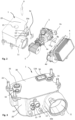
- the Figures 1 , 2 , 8 and 9 show an oil feed module 100 which comprises an oil pan 1, a pump 3 with a drive 2, an oil filter holder 11 with an oil filter 5 and a heat exchanger 4.
- the oil feed module 100 can have a separate oil filter holder 11, i.e.
- the oil filter holder 11 is connected in a fluid-communicating manner, in particular via a line or a channel, to the oil channel 15 shown in the figures, for which purpose the oil pan 1 or its housing 10, 20, 30 or housing frame 10 can have a connection for connection to the oil filter holder 11.
- the pump is arranged in structural or geometric terms between the heat exchanger 4 and the oil pan 1, for example, attached to a connecting wall 10a of the housing frame 10.
- the pump 3 is connected to the oil pan 10 by means of several screw bolts 3g ( Figure 2 ), which are screwed into an internal thread of the housing frame 10 or the connecting wall 10a, to the housing frame 10 or the connecting wall 10a.
- the heat exchanger 4 is secured by means of several screw bolts ( Figures 8 and 9 ) to the oil filter holder 11 and the drive 2 and/or the pump 3.
- the oil feed module 100 serves to supply oil for cooling and/or lubrication to a machine unit, such as an electric motor transmission unit, in particular for a motor vehicle, and to collect the returning oil and to supply it again to the To do this, the oil feed module 100 is attached to the unit with the top of the oil pan 1, on which supply outlets 31, 32 are located.
- the supply outlets 31, 32 are formed by a housing cover 30 in the example shown. Oil is supplied to the unit via the supply outlets 31, 32.
- Oil can be supplied to the electric motor via one of the supply outlets 31, 32 and to the gearbox via the other of the supply outlets 31, 32.
- Return inlets 33, 34 are also arranged on the top of the oil pan 1, via which oil flowing back from the unit is supplied to the oil pan 1.
- the return inlets 33, 34 are formed by the housing cover 30 in the example shown.
- oil from the electric motor can be returned to the oil pan 1 or the oil delivery module via one of the return inlets 33, 34 and oil from the transmission via the other of the return inlets 33, 34.
- the oil pan 1 and thus the components of the oil delivery module 100 attached to it are connected by means of several screw bolts 22 ( Figure 1 ) to the unit.
- the housing 10, 20, 30 of the oil pan 1 is clamped between a head of the screw bolt 22 and the unit.
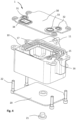
- the oil pan 1 has a housing 10, 20, 30 which comprises a housing frame 10, a housing base 20 and a housing cover 30.
- the housing frame 10 is arranged between the housing cover 30 and the housing base 20.
- the housing frame 10 forms a circumferential side wall, on the downward-facing end face of which the housing base 20 is attached and on the upper-facing end face of which the housing cover 30 is attached.
- the circumferential side wall has four side wall sections which together surround an oil receiving space 18, for example in a rectangular shape.
- One of these side wall sections is designed as a connecting wall 10a, namely the one which faces the pump 3 and/or the heat exchanger 4.
- the housing cover 30 and the housing base 20 are arranged parallel to one another and the four side wall sections are the same height.
- opposite side wall sections can be of different heights and the two side wall sections that connect the opposite side wall sections can be wedge-shaped, whereby the housing cover 30 and housing base 20 are arranged obliquely, in particular at an acute angle to each other.
- This variant makes it possible to achieve a particularly compact design of the oil pan, which nevertheless leaves sufficient space on the higher, ie the connecting wall 10a, of the opposite side wall sections for, for example, an oil filter holder 11, optionally a sensor holder 6a and the Pump connections 12, 13, 14, which are explained below.
- the side wall shown in the example also requires little space, but is not quite as compact as the variant, but is structurally somewhat simpler.
- the housing base 20 is kept simple in comparison to the housing frame 10 and housing cover 30.
- the housing base 20 closes off an oil receiving space 18 from below and is essentially plate-shaped.
- the more complex housing frame 10 and housing cover 30 together form oil channels 15, 16, 17.
- the housing cover 30 closes off the oil receiving space 18 from above.
- the housing frame 10 is open at the top and bottom and is sealed fluid-tight with the housing base 20 and housing cover 30 mounted there.
- the housing frame 10 integrally forms an oil filter holder 11, a sensor holder 6a and the pump connections 12, 13, 14, for example in the form of a tube or nozzle.
- connection wall 10a integrally forms the oil filter holder 11 and the pump connections 12, 13, 14, as well as optionally several internal threads for fastening the pump 3 to the connection wall 10a.
- the internal threads can each be formed by a threaded bushing that protrudes from the connecting wall in the direction of pump 3.
- the housing frame 10, the housing base 20 and the housing cover 30 can be made of plastic.
- the housing base 20 can be connected to the housing frame 10 and the housing cover 30 can be connected to the housing frame 10 by gluing or welding.
- the housing frame 10, the housing base 20 and the housing cover 30 can be screwed together.
- the housing base 20 has an oil drain device in the form of an oil drain plug 21.
- the oil drain plug 21 is screwed into an internal thread of the housing base 20 and can be removed to drain the oil.
- the housing 10, 20, 30 forms an oil pan with the oil receiving chamber 18 enclosed by it.
- the oil flowing back from the unit is stored in the oil receiving chamber 18, whereby oil can be sucked out of the oil receiving chamber 18 by means of the pump 3 and fed back to the unit.
- the oil pan 1 further comprises an intake channel 12a which extends into the oil receiving space 18 and which has an opening 12b through which oil can be sucked in from the oil receiving space 18 through the intake channel 12a by the pump 3.
- the intake channel 12a is designed as an intake pipe which is inserted with one end into a channel receptacle 12c of the housing frame 10.
- a gap between an inner circumference of the channel receptacle 12c and an outer circumference of the tubular intake channel 12a is sealed by means of a seal 12e ( Figure 6 ) sealed.
- the housing frame 10 in particular the connection wall 10a, forms a passage which connects a first pump inlet connection 12 formed on the outside of the housing frame 10 and the channel receptacle 12c formed on the inside of the housing frame 10, whereby oil can be conveyed from the oil pan 18 via the intake channel 12a and the passage to the first pump inlet connection 12.
- This passage crosses the oil channels 15 and 17 ( Figure 5 ).
- a first pump inlet 3c ( Figures 7 and 8th ) of the pump 3 can be connected or is connected. This allows the pump 3 to suck oil from the oil receiving chamber 18.
- the housing 10, 20, 30, in particular the housing frame 10, has a partition wall 19 which divides the oil receiving space 18 into a first section 18a and a second section 18b.
- the second section 18b has a smaller volume than the first section 18a.
- the intake channel 12a extends from the channel receptacle 12c through the second section 18b and the partition wall 19 into the first section 18a.
- the intake opening 12b is arranged in the first section 18a. As a result, oil is sucked in from the first section 18a.
- the partition wall 19 also has a passage 19a that connects the first and second sections 18a, 18b to one another in a fluid-communicating manner.
- the passage 19a causes a throttled fluid exchange between the sections 18a and 18b.
- the passage 19a allows oil to flow from the second section 18b into the first section 18a.
- the passage 19b allows oil to flow from the first section 18a into the second section 18b, for example if so much oil is pumped into the first section 18a that it would become overfilled.
- An oil filter holder 11 is integrally formed on the housing frame 10, in particular the connecting wall 10a, into which the oil filter 5 or an oil filter insert can be inserted.
- the oil filter holder 11 is connected on the one hand to the first oil channel 15 and on the other hand to the Heat exchanger 4 is connected in a fluid-communicating manner. This allows oil from the first flow or the first fluid circuit to be conveyed from the pump 3 via the heat exchanger 4 through the oil filter 5 arranged in the oil filter holder 11 into the first oil channel 15.
- the oil filter 5 can be used to filter impurities in the oil, such as abrasion, from the oil circuit.
- the oil filter holder 11 has a peripheral wall - cylindrical in the example shown - into which the oil filter 5 - also exemplary cylindrical - is inserted or which surrounds the oil filter 5 over its circumference.
- the peripheral wall is positioned in relation to the connecting wall 10a facing the pump 3 in such a way that a central axis of the peripheral wall is perpendicular or approximately perpendicular in relation to the connecting wall 10a.
- the peripheral wall of the oil filter holder 11 has an opening on its front side facing the connection wall 10a, through which the oil filter 5 can be inserted into the peripheral wall or removed from the peripheral wall for replacement. The opening is closed by a cover 4d formed on the heat exchanger 4.
- the connection wall 10a or the housing frame 10 forms an end of the peripheral wall opposite the opening.
- the cover has a passage which connects the heat exchanger 4 to the oil filter holder 11 in a fluid-communicating manner such that oil of the first flow can be conveyed from the heat exchanger 4 into the oil filter holder 11.
- the peripheral wall of the oil filter holder forms on its outside one or more internally threaded bushings which have an internal thread into which screw bolts for fastening the cover 4d and/or the heat exchanger 4 to the oil filter holder 11 are or can be screwed ( Figure 2 ).
- the oil filter holder 11 is connected in a fluid-communicating manner to a first supply outlet 31 and a second supply outlet 32 via a first oil channel 15.
- the unit is connected in a fluid-communicating manner to the first and second supply outlets 31, 32, so that oil can be conveyed from the oil filter holder 11 via the first oil channel 15 to the supply outlets 31, 32 and thus into the unit.
- the first oil channel 15 can optionally be referred to as a unit supply channel.
- the first oil channel 15 is formed between the housing frame 10 and the housing cover 30 joined to it. In the embodiment shown, the housing frame 10 and the housing cover 30 together form the first oil channel 15.
- the housing frame 10 has, on its end face facing the housing cover 30, a channel section of the first oil channel 15 that is groove-shaped in the longitudinal direction of the channel or in the direction of channel travel.
- the Housing cover 30 covers the channel-shaped channel section of the first oil channel 15 to form a closed channel cross-section.
- housing cover 30 also has a channel-shaped channel section that is designed to be congruent with the channel-shaped channel section of housing frame 10 and that covers it. In principle, however, designs are also possible in which the housing cover is designed to be flat in the section that covers the channel-shaped channel section of housing frame 10, ie without a channel-shaped design.
- the first oil channel 15 branches off from the oil filter holder 11 or a filter outlet 15a, at which the oil from the oil filter 5 enters the first oil channel 15, with a first branch to the first supply outlet 31 and with a second branch to a second supply outlet 32.
- the first supply outlet 31 is located at or above a transfer point, the position of which is indicated with the reference number 31a in Figure 5
- the first supply outlet 32 is located at or above a transfer point, the position of which is indicated by the reference numeral 32a in Figure 5 is shown by way of example.
- the fluid sucked in by the pump 3 via the intake channel 12a is conveyed via a first pump outlet 3a, which is connected to the oil filter holder 11 in a fluid-communicating manner, into the oil filter holder 11 and there is filtered of impurities by the oil filter 5.
- the filtered oil is conveyed via the first oil channel 15 to the supply outlets 31, 32 and fed to the unit.
- the heat exchanger 4 has a first pump outlet connection 4c, which is connected to the tubular or nozzle-shaped pump outlet 3a.
- the oil pumped by the pump 3 via the first pump outlet 3a to the oil filter holder 11 flows through the heat exchanger 4 and releases heat energy there to a cooling medium.
- the cooling medium is fed to the heat exchanger 4 via a coolant inlet 4a and discharged from the heat exchanger 4 via a coolant outlet 4b.
- the heat energy released by the oil is transferred in the heat exchanger 4 to the coolant, which flows through the heat exchanger 4, and is discharged from the heat exchanger with the coolant.
- the mass flow of the coolant through the heat exchanger 4 can be controlled, for example, by means of a valve in order to be able to adjust the temperature of the oil in the oil filter system 100.
- the housing 10, 20, 30, in particular the housing frame 10, has in the embodiment shown a sensor receptacle 6a into which a temperature sensor 6 can be inserted ( Figure 2 ), which is configured such that it can measure the temperature of the oil flowing through the first oil channel 15, in particular the second branch of the first oil channel 15.
- a signal output by the temperature sensor 6, which contains information regarding the oil temperature can be output to a control unit or a regulating unit, which, depending on the measured temperature, controls the valve that controls the mass flow of the coolant through the heat exchanger 4.
- the valve can be controlled such that the mass flow through the heat exchanger 4 is reduced or blocked if the temperature measured by the temperature sensor 6 is less than a target temperature.
- the valve can be controlled such that it starts or increases the mass flow of the coolant flowing through the heat exchanger 4 if the temperature measured by the temperature sensor 6 is above the target temperature of the oil.
- the oil pan 1, in particular the housing cover 30 and/or the housing frame 10, has a first return inlet 33, with which oil can be led from the unit into the oil pan 1.
- the first return inlet 33 is arranged on the top of the oil pan 1 or on the side of the oil filter module 1 facing the unit.
- a second oil channel 16 is arranged or formed between the housing frame 10 and the housing cover 30, which connects the first return inlet 33 in a fluid-communicating manner to a second pump inlet connection 13, which is formed by the housing frame 10, in particular the connection wall 10a, on the outside thereof.
- a second pump inlet 3d formed on the pump 3 ( Figure 7 ) is connectable or connected to the second pump inlet connection 13.
- the second oil channel 16 can optionally be referred to as a return intake channel.
- the first return inlet 33 is located at a transfer point, the position of which is indicated with the reference number 33b in Figure 5 as shown as an example, into the oil channel 16.
- the oil sucked in by the pump 3 via the second pump inlet 3d is discharged via a second pump outlet 3b of the pump 3 via a third oil channel 17, which, for example, is provided with a Figure 5 shown opening 17a, into the oil receiving chamber 18, in particular its first section 18a, into the first section 18a.
- the third oil channel 17 can optionally be referred to as a return supply channel.
- the passage connecting the second pump outlet port 14 and the third oil channel 17 is arranged between the first oil channel 15 and the passage connecting the second pump inlet port 13 and the second oil channel 16.
- the housing frame 10, in particular the connection wall 10a, has on its outside a pump outlet connection 14 which can be connected or is connected to the second pump outlet 3b of the pump 3.
- the pump outlet connection 14 is connected to the first section 18a in a fluid-communicating manner via the third oil channel 17.
- the housing frame 10 and the housing cover 30 together form the second oil channel 16 and the third oil channel 17, respectively.
- the housing frame 10 has, on its front side facing the housing cover 30, a channel-shaped channel section that is open towards the housing cover 30 in the channel direction and is covered by the housing cover 30, in particular a flat or channel-shaped channel section, to form a closed channel cross-section.
- the housing frame 10 has, on its front side facing the housing cover 30, a channel-shaped channel section that is open towards the housing cover 30 in the channel direction and is covered by the housing cover 30 to form a closed channel cross-section.
- the oil channels 15, 16, 17 are each formed by a channel-shaped channel section formed on the housing frame 10 and the housing cover 30, which covers the channel-shaped channel sections.
- Such Design allows space-saving construction and simple production of the oil channels 15, 16, 17.
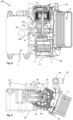
- the pump 3 shown is a double-flow pump with two separate fluid circuits or flows.
- the pump 3 has a first pump set Pi for the first flow and a second pump set P 2 for the second flow.
- the first pump set Pi and the second pump set P 2 are - as in Figure 8 shown - each designed as an internal gear pump.
- the first and second pump sets P 1 , P 2 each comprise an inner gear which sits on the drive shaft 3f in a rotationally fixed manner and has an external toothing, and an outer gear which has an internal toothing which meshes with the external toothing at one point on the circumference.
- An axis of rotation of the outer gear is arranged offset from the center axis of the drive shaft 3f.
- the pump 3 can convey the first fluid circuit via the pump inlet 3c to the pump outlet 3a.
- the pump 3 can convey the second fluid circuit, which is separate from the first fluid circuit and is designed for bilge operation, for example, from the second pump inlet 3d to the second pump outlet 3b.
- the pump 3 can in particular have two conveying elements, one for the first fluid circuit and one for the second fluid circuit. Alternatively, two separate pumps can be provided instead of a double-flow pump.
- the Figure 7 The pump 3 shown is driven by a drive 2 arranged on it.
- the drive 2 is an electric motor.
- the drive 2 can have a plug receptacle 2a to which a power supply for driving the pump 2 can be connected.
- the oil pan 1, in particular the housing frame 10 and/or the housing cover 30, has a second return inlet 34 on its upper side or the side facing the unit, which opens directly into the first section 18a of the oil pan 18.
- a deflector 12d for example in the form of a plate, is arranged between the second return inlet 34 and the intake opening 12b of the intake channel 12a, which is configured in such a way that it prevents the fluid flowing back into the first section 18a via the second return inlet 34 from flowing directly into the intake opening 12b.
- the deflector 12d which is formed in particular by or on the intake duct 12a, can for example, it can be plate-shaped and/or above the intake opening 12b or - as in the embodiment shown in the figures - collar-shaped around the intake-side end of the intake pipe 12a.
- the deflector 12d can extend parallel or approximately parallel to the housing base 20.
- a strainer 33a is arranged in the first return inlet 33 such that the oil flowing back from the unit into the first return inlet 33 flows through it.
- the strainer 33a can span the full flow cross section of the first return inlet 33.
- a strainer 34a is arranged in the second return inlet 34 such that the oil flowing from the unit into the second return inlet 34 flows through it.
- the strainer 34a can span the entire flow cross section of the second return inlet 24.
- the pump inlet port 13 may be inserted into the second pump inlet 3d.
- the gap formed between the outer periphery of the pump inlet port 13 and the inner periphery of the pump inlet 3d may be sealed by means of a seal 3e.
- the pump outlet port 14 may be inserted into the pump outlet 3b.
- the gap formed between an outer periphery of the pump outlet port 14 and an inner periphery of the pump outlet 3b may be sealed by means of a seal 3e.
- the pump inlet connection 12 can be inserted into the pump inlet 3c.
- the gap formed between an outer circumference of the pump inlet connection 12 and an inner circumference of the pump inlet 3c can be sealed by means of a seal 3e.
- the seals 3e can be formed, for example, as a sealing ring or O-ring.
- the flow cross section of the second return inlet 34 is larger than the flow cross section of the first return inlet.
- the pump 3 is positioned geometrically or structurally between the drive 2 and the oil filter holder 11.
- the drive-pump unit formed from the drive 2 and the pump 3 has a drive shaft 3f for the pump 3.
- the drive shaft 3f is arranged concentrically to a rotor of the drive 2 and a common, continuous shaft of the drive 2 and the pump 3.
- an imaginary extension or a longitudinal axis of the drive shaft 3f can run through the oil filter holder 11 and/or be arranged perpendicular to the central axis of the oil filter holder 11.
- the drive shaft 3f is arranged horizontally with respect to the earth's gravitational field or transversely, in particular vertically, with respect to the vertical axis of the oil delivery module 100 or the oil pan 1.
- the drive shaft 3f can extend in the direction between the two side wall sections of the housing frame 10 that delimit the connecting wall 10a, parallel or approximately parallel to the connecting wall 10a and/or parallel to one or both of the housing cover 30 and the housing base 20.
- the drive shaft 3f is arranged within a vertical projection of the connecting wall 9a and/or between planes spanned by the housing cover 30 and the housing base 20. This results in a compact and flat design of the oil feed module 100, which can therefore also be used in vehicles with a low center of gravity, for example sports cars.
- the pump has the first pump inlet 3c, via which oil can be pumped from the oil pan 1 into the pump, ie the first pump set P 1 , and the first pump outlet 3a, via which oil can be pumped from the pump, ie the first pump set Pi into the heat exchanger 4.
- the first pump inlet 3c or an inlet channel center axis M 1 of the first pump inlet ( Figure 8 ), and the first pump outlet 3a or an outlet channel center axis M 2 of the first pump outlet 3a, are arranged in a line and perpendicular to the drive shaft 3f.
- first tubular or nozzle-shaped pump inlet connection 12 and the first pump inlet 3c form the inlet channel longitudinal axis M 1 and the first tubular or nozzle-shaped pump outlet 3a and the first pump outlet connection 4c form the outlet channel longitudinal axis M 2 .
- the first pump set Pi for the first flow and the second pump set P 2 for the second flow are arranged offset from one another along the drive shaft 3f.
- An inlet opening is formed between the first pump set Pi and an inlet channel running from the first inlet connection 3c along the inlet channel center axis M 1 , which connects the inlet channel to a suction area of the first pump insert Pi.
- An outlet opening can be formed between the first pump set Pi and an outlet channel running from the first outlet connection 3a along the outlet channel center axis M 2 , which connects the outlet channel to a pressure area of the first pump set Pi.
- the inlet channel 3c and the Outlet channel 3a and/or the inlet channel center axis M 1 and the outlet channel center axis M 2 are arranged between the first and second pump sets P 1 , P 2 with respect to the longitudinal direction of the drive shaft 3f.
Landscapes
- Engineering & Computer Science (AREA)
- General Engineering & Computer Science (AREA)
- Mechanical Engineering (AREA)
- Lubrication Details And Ventilation Of Internal Combustion Engines (AREA)
- General Details Of Gearings (AREA)
- Details And Applications Of Rotary Liquid Pumps (AREA)
Applications Claiming Priority (2)
| Application Number | Priority Date | Filing Date | Title |
|---|---|---|---|
| DE102023101650 | 2023-01-24 | ||
| EP23196072 | 2023-09-07 |
Publications (1)
| Publication Number | Publication Date |
|---|---|
| EP4407152A1 true EP4407152A1 (fr) | 2024-07-31 |
Family
ID=89541937
Family Applications (2)
| Application Number | Title | Priority Date | Filing Date |
|---|---|---|---|
| EP24152733.2A Pending EP4407151A1 (fr) | 2023-01-24 | 2024-01-18 | Carter d'huile, en particulier module de filtre à huile, doté d'un boîtier en plusieurs parties |
| EP24153760.4A Pending EP4407152A1 (fr) | 2023-01-24 | 2024-01-24 | Module de refoulement d'huile destiné à alimenter un groupe d'un véhicule automobile |
Family Applications Before (1)
| Application Number | Title | Priority Date | Filing Date |
|---|---|---|---|
| EP24152733.2A Pending EP4407151A1 (fr) | 2023-01-24 | 2024-01-18 | Carter d'huile, en particulier module de filtre à huile, doté d'un boîtier en plusieurs parties |
Country Status (2)
| Country | Link |
|---|---|
| US (1) | US12535022B2 (fr) |
| EP (2) | EP4407151A1 (fr) |
Families Citing this family (4)
| Publication number | Priority date | Publication date | Assignee | Title |
|---|---|---|---|---|
| US20260022650A1 (en) * | 2024-07-17 | 2026-01-22 | Mahle International Gmbh | Sump and heat exchanger module |
| GB2643746A (en) * | 2024-08-30 | 2026-03-04 | Jaguar Land Rover Ltd | Lubricant sump |
| DE102024128316A1 (de) * | 2024-09-30 | 2026-04-02 | Voith Patent Gmbh | Ölwanne für eine Antriebseinheit |
| FR3166927A1 (fr) | 2024-09-30 | 2026-04-03 | Purflux Filtration | Unite de collecte et stockage, incluant un carter d’huile de transmission et des clapets anti-remontee d’huile |
Citations (2)
| Publication number | Priority date | Publication date | Assignee | Title |
|---|---|---|---|---|
| EP2154342A1 (fr) * | 2008-08-14 | 2010-02-17 | Mann + Hummel Gmbh | Dispositif de refroidisseur d'huile et de pompe à huile pour un moteur à combustion interne |
| DE202020105684U1 (de) * | 2020-10-05 | 2020-10-30 | Mahle International Gmbh | Ölpumpenmodul für ein Kraftfahrzeug |
Family Cites Families (26)
| Publication number | Priority date | Publication date | Assignee | Title |
|---|---|---|---|---|
| US2938601A (en) * | 1958-03-20 | 1960-05-31 | Gen Motors Corp | Engine oil pan |
| US3029661A (en) | 1959-07-09 | 1962-04-17 | Falk Corp | All purpose speed reducer |
| JPS60155710U (ja) | 1984-03-27 | 1985-10-17 | 本田技研工業株式会社 | 内燃機関における潤滑装置 |
| DE19619977C2 (de) | 1996-05-17 | 1998-07-02 | Daimler Benz Ag | Ölwanne für eine Brennkraftmaschine |
| US6142257A (en) | 1998-07-13 | 2000-11-07 | Briggs And Stratton Corporation | Oil pickup tube for internal combustion engine |
| US6041752A (en) * | 1998-11-04 | 2000-03-28 | Technology Holdings, Inc. | Moldable integrated oil pan and suction tube for an internal combustion engine |
| US6584950B1 (en) * | 2002-05-29 | 2003-07-01 | Bayer Corporation | Oil pan |
| GB2389625A (en) | 2002-06-13 | 2003-12-17 | Cnh Uk Ltd | Oil sump |
| DE10325670B4 (de) | 2003-06-06 | 2006-03-16 | Mtu Friedrichshafen Gmbh | Abdeckplatte für ein Kurbelgehäuse |
| DE10357175B4 (de) * | 2003-12-06 | 2006-03-16 | Mtu Friedrichshafen Gmbh | Bodenplatte für ein Kurbelgehäuse |
| DE102004053717B4 (de) | 2004-11-06 | 2006-08-10 | Mtu Friedrichshafen Gmbh | Bodenplatte für ein Kurbelgehäuse |
| DE102007023406A1 (de) | 2007-05-18 | 2008-11-20 | GM Global Technology Operations, Inc., Detroit | Ölwanne |
| DE102007040666A1 (de) * | 2007-08-27 | 2009-03-05 | Mann + Hummel Gmbh | Ölwanne |
| DE102007060411A1 (de) * | 2007-12-14 | 2008-09-04 | Daimler Ag | Ölwanne |
| DE102008031684B4 (de) | 2008-07-04 | 2020-02-06 | Mahle International Gmbh | Kühleinrichtung |
| DE202008010222U1 (de) * | 2008-07-31 | 2009-12-10 | Mann+Hummel Gmbh | Ölwannenanordnung |
| DE202008010865U1 (de) | 2008-08-14 | 2010-01-07 | Mann+Hummel Gmbh | Ölwanne |
| US8272480B2 (en) * | 2009-03-12 | 2012-09-25 | Mahle International Gmbh | Oil pan integrated with filter and other components |
| JP2011007042A (ja) * | 2009-05-29 | 2011-01-13 | Daikyonishikawa Corp | オイルパン構造及びオイルパン内部を仕切るための仕切部材 |
| FR2961859B1 (fr) | 2010-06-24 | 2012-07-06 | Mecaplast Sa | Carter d'huile destine a etre fixe a un bloc moteur |
| GB2486017B (en) | 2010-12-02 | 2016-03-23 | Gm Global Tech Operations Inc | Lubrication circuit layout |
| US8887688B1 (en) | 2011-03-22 | 2014-11-18 | Gene Neal | Oil filtering and cooling system for compression ignition engines |
| DE102012100988A1 (de) | 2012-02-07 | 2013-08-08 | Elringklinger Ag | Rohrkörper und Ölwanne mit einem derartigen Rohrkörper |
| US9771840B2 (en) * | 2015-02-24 | 2017-09-26 | GM Global Technology Operations LLC | Oil pan and engine assembly including the oil pan |
| JP6589582B2 (ja) | 2015-11-12 | 2019-10-16 | いすゞ自動車株式会社 | 内燃機関のアース構造 |
| DE102022200696A1 (de) * | 2022-01-21 | 2023-07-27 | Mahle International Gmbh | System für ein Kraftfahrzeug |
-
2024
- 2024-01-18 EP EP24152733.2A patent/EP4407151A1/fr active Pending
- 2024-01-23 US US18/420,225 patent/US12535022B2/en active Active
- 2024-01-24 EP EP24153760.4A patent/EP4407152A1/fr active Pending
Patent Citations (2)
| Publication number | Priority date | Publication date | Assignee | Title |
|---|---|---|---|---|
| EP2154342A1 (fr) * | 2008-08-14 | 2010-02-17 | Mann + Hummel Gmbh | Dispositif de refroidisseur d'huile et de pompe à huile pour un moteur à combustion interne |
| DE202020105684U1 (de) * | 2020-10-05 | 2020-10-30 | Mahle International Gmbh | Ölpumpenmodul für ein Kraftfahrzeug |
Also Published As
| Publication number | Publication date |
|---|---|
| EP4407151A1 (fr) | 2024-07-31 |
| US12535022B2 (en) | 2026-01-27 |
| US20240247601A1 (en) | 2024-07-25 |
Similar Documents
| Publication | Publication Date | Title |
|---|---|---|
| EP4407152A1 (fr) | Module de refoulement d'huile destiné à alimenter un groupe d'un véhicule automobile | |
| EP4407150B1 (fr) | Carter d'huile, en particulier module de filtre à huile, doté d'un boîtier en plusieurs parties | |
| EP1766207B1 (fr) | Module huile/liquide de refroidissement avec systeme d'entretien du liquide de refroidissement | |
| DE102011076465B4 (de) | Zentrifugalabscheider zum Abscheiden von Ölnebel aus dem Kurbelgehäuseentlüftungsgas einer Brennkraftmaschine | |
| DE19681509B4 (de) | Verbrennungskraftmaschine | |
| EP4242431B1 (fr) | Système de transport de fluide comprenant un module de fluide séparé | |
| DE19520267A1 (de) | Kolbenkompressor mit Öltrenneinrichtung | |
| EP3504433A1 (fr) | Ensemble motopompe | |
| EP0921297B1 (fr) | Moteur multi-cylindres à pistons à combustion interne | |
| EP4242511B1 (fr) | Système de transport de fluide pour alimenter un groupe de machines en fluide | |
| EP1574714B1 (fr) | Unité de pompage | |
| EP1648584A1 (fr) | Filtre a carburant | |
| EP0838577A1 (fr) | Système d'amenée d'huile pour moteur à combustion | |
| DE4135442C1 (fr) | ||
| DE102004025450A1 (de) | Ölwanne für einen Motor und/oder ein Getriebe | |
| AT501798A4 (de) | Aufgeladene brennkraftmaschine | |
| EP1774152A1 (fr) | Module huile avec pompe a eau et echangeur de chaleur | |
| EP2076658A2 (fr) | Système de lubrification pour un moteur à combustion interne comprenant un turbocompresseur à gaz d'échappement | |
| WO2013050099A1 (fr) | Agencement d'un module à huile et d'une pompe à huile sur un moteur à combustion interne | |
| EP4170173A1 (fr) | Compresseur à vis avec canaux de lubrification des paliers | |
| DE102024129530A1 (de) | Ölkühlermodul | |
| DE10218338A1 (de) | Brennkraftmaschine mit einer Ölwanne | |
| DE102024124452A1 (de) | Fluidfördermodul mit Entschäumungsstruktur | |
| DE202022107091U1 (de) | Brennkraftmaschine | |
| DE202004015033U1 (de) | Doppelpumpe |
Legal Events
| Date | Code | Title | Description |
|---|---|---|---|
| PUAI | Public reference made under article 153(3) epc to a published international application that has entered the european phase |
Free format text: ORIGINAL CODE: 0009012 |
|
| STAA | Information on the status of an ep patent application or granted ep patent |
Free format text: STATUS: THE APPLICATION HAS BEEN PUBLISHED |
|
| AK | Designated contracting states |
Kind code of ref document: A1 Designated state(s): AL AT BE BG CH CY CZ DE DK EE ES FI FR GB GR HR HU IE IS IT LI LT LU LV MC ME MK MT NL NO PL PT RO RS SE SI SK SM TR |
|
| STAA | Information on the status of an ep patent application or granted ep patent |
Free format text: STATUS: REQUEST FOR EXAMINATION WAS MADE |
|
| 17P | Request for examination filed |
Effective date: 20250131 |
|
| GRAP | Despatch of communication of intention to grant a patent |
Free format text: ORIGINAL CODE: EPIDOSNIGR1 |
|
| STAA | Information on the status of an ep patent application or granted ep patent |
Free format text: STATUS: GRANT OF PATENT IS INTENDED |
|
| INTG | Intention to grant announced |
Effective date: 20260313 |