EP4407225A1 - Wasseranschlussverschlussanordnung - Google Patents
Wasseranschlussverschlussanordnung Download PDFInfo
- Publication number
- EP4407225A1 EP4407225A1 EP23461505.2A EP23461505A EP4407225A1 EP 4407225 A1 EP4407225 A1 EP 4407225A1 EP 23461505 A EP23461505 A EP 23461505A EP 4407225 A1 EP4407225 A1 EP 4407225A1
- Authority
- EP
- European Patent Office
- Prior art keywords
- fill port
- flow channel
- ball
- sleeve
- port assembly
- Prior art date
- Legal status (The legal status is an assumption and is not a legal conclusion. Google has not performed a legal analysis and makes no representation as to the accuracy of the status listed.)
- Granted
Links
Images



Classifications
-
- F—MECHANICAL ENGINEERING; LIGHTING; HEATING; WEAPONS; BLASTING
- F16—ENGINEERING ELEMENTS AND UNITS; GENERAL MEASURES FOR PRODUCING AND MAINTAINING EFFECTIVE FUNCTIONING OF MACHINES OR INSTALLATIONS; THERMAL INSULATION IN GENERAL
- F16L—PIPES; JOINTS OR FITTINGS FOR PIPES; SUPPORTS FOR PIPES, CABLES OR PROTECTIVE TUBING; MEANS FOR THERMAL INSULATION IN GENERAL
- F16L37/00—Couplings of the quick-acting type
- F16L37/28—Couplings of the quick-acting type with fluid cut-off means
- F16L37/38—Couplings of the quick-acting type with fluid cut-off means with fluid cut-off means in only one of two pipe-end fittings
- F16L37/47—Couplings of the quick-acting type with fluid cut-off means with fluid cut-off means in only one of two pipe-end fittings with a tap or cock
-
- B—PERFORMING OPERATIONS; TRANSPORTING
- B67—OPENING, CLOSING OR CLEANING BOTTLES, JARS OR SIMILAR CONTAINERS; LIQUID HANDLING
- B67D—DISPENSING, DELIVERING OR TRANSFERRING LIQUIDS, NOT OTHERWISE PROVIDED FOR
- B67D7/00—Apparatus or devices for transferring liquids from bulk storage containers or reservoirs into vehicles or into portable containers, e.g. for retail sale purposes
- B67D7/02—Apparatus or devices for transferring liquids from bulk storage containers or reservoirs into vehicles or into portable containers, e.g. for retail sale purposes for transferring liquids other than fuel or lubricants
- B67D7/0288—Container connection means
- B67D7/0294—Combined with valves
-
- F—MECHANICAL ENGINEERING; LIGHTING; HEATING; WEAPONS; BLASTING
- F16—ENGINEERING ELEMENTS AND UNITS; GENERAL MEASURES FOR PRODUCING AND MAINTAINING EFFECTIVE FUNCTIONING OF MACHINES OR INSTALLATIONS; THERMAL INSULATION IN GENERAL
- F16K—VALVES; TAPS; COCKS; ACTUATING-FLOATS; DEVICES FOR VENTING OR AERATING
- F16K11/00—Multiple-way valves, e.g. mixing valves; Pipe fittings incorporating such valves
- F16K11/02—Multiple-way valves, e.g. mixing valves; Pipe fittings incorporating such valves with all movable sealing faces moving as one unit
- F16K11/08—Multiple-way valves, e.g. mixing valves; Pipe fittings incorporating such valves with all movable sealing faces moving as one unit comprising only taps or cocks
- F16K11/087—Multiple-way valves, e.g. mixing valves; Pipe fittings incorporating such valves with all movable sealing faces moving as one unit comprising only taps or cocks with spherical plug
- F16K11/0873—Multiple-way valves, e.g. mixing valves; Pipe fittings incorporating such valves with all movable sealing faces moving as one unit comprising only taps or cocks with spherical plug the plug being only rotatable around one spindle
-
- F—MECHANICAL ENGINEERING; LIGHTING; HEATING; WEAPONS; BLASTING
- F16—ENGINEERING ELEMENTS AND UNITS; GENERAL MEASURES FOR PRODUCING AND MAINTAINING EFFECTIVE FUNCTIONING OF MACHINES OR INSTALLATIONS; THERMAL INSULATION IN GENERAL
- F16K—VALVES; TAPS; COCKS; ACTUATING-FLOATS; DEVICES FOR VENTING OR AERATING
- F16K11/00—Multiple-way valves, e.g. mixing valves; Pipe fittings incorporating such valves
- F16K11/10—Multiple-way valves, e.g. mixing valves; Pipe fittings incorporating such valves with two or more closure members not moving as a unit
- F16K11/14—Multiple-way valves, e.g. mixing valves; Pipe fittings incorporating such valves with two or more closure members not moving as a unit operated by one actuating member, e.g. a handle
- F16K11/16—Multiple-way valves, e.g. mixing valves; Pipe fittings incorporating such valves with two or more closure members not moving as a unit operated by one actuating member, e.g. a handle which only slides, or only turns, or only swings in one plane
- F16K11/163—Multiple-way valves, e.g. mixing valves; Pipe fittings incorporating such valves with two or more closure members not moving as a unit operated by one actuating member, e.g. a handle which only slides, or only turns, or only swings in one plane only turns
-
- F—MECHANICAL ENGINEERING; LIGHTING; HEATING; WEAPONS; BLASTING
- F16—ENGINEERING ELEMENTS AND UNITS; GENERAL MEASURES FOR PRODUCING AND MAINTAINING EFFECTIVE FUNCTIONING OF MACHINES OR INSTALLATIONS; THERMAL INSULATION IN GENERAL
- F16K—VALVES; TAPS; COCKS; ACTUATING-FLOATS; DEVICES FOR VENTING OR AERATING
- F16K27/00—Construction of housing; Use of materials therefor
- F16K27/06—Construction of housing; Use of materials therefor of taps or cocks
- F16K27/067—Construction of housing; Use of materials therefor of taps or cocks with spherical plugs
-
- F—MECHANICAL ENGINEERING; LIGHTING; HEATING; WEAPONS; BLASTING
- F16—ENGINEERING ELEMENTS AND UNITS; GENERAL MEASURES FOR PRODUCING AND MAINTAINING EFFECTIVE FUNCTIONING OF MACHINES OR INSTALLATIONS; THERMAL INSULATION IN GENERAL
- F16K—VALVES; TAPS; COCKS; ACTUATING-FLOATS; DEVICES FOR VENTING OR AERATING
- F16K5/00—Plug valves; Taps or cocks comprising only cut-off apparatus having at least one of the sealing faces shaped as a more or less complete surface of a solid of revolution, the opening and closing movement being predominantly rotary
- F16K5/06—Plug valves; Taps or cocks comprising only cut-off apparatus having at least one of the sealing faces shaped as a more or less complete surface of a solid of revolution, the opening and closing movement being predominantly rotary with plugs having spherical surfaces; Packings therefor
- F16K5/0605—Plug valves; Taps or cocks comprising only cut-off apparatus having at least one of the sealing faces shaped as a more or less complete surface of a solid of revolution, the opening and closing movement being predominantly rotary with plugs having spherical surfaces; Packings therefor with particular plug arrangements, e.g. particular shape or built-in means
-
- F—MECHANICAL ENGINEERING; LIGHTING; HEATING; WEAPONS; BLASTING
- F16—ENGINEERING ELEMENTS AND UNITS; GENERAL MEASURES FOR PRODUCING AND MAINTAINING EFFECTIVE FUNCTIONING OF MACHINES OR INSTALLATIONS; THERMAL INSULATION IN GENERAL
- F16K—VALVES; TAPS; COCKS; ACTUATING-FLOATS; DEVICES FOR VENTING OR AERATING
- F16K5/00—Plug valves; Taps or cocks comprising only cut-off apparatus having at least one of the sealing faces shaped as a more or less complete surface of a solid of revolution, the opening and closing movement being predominantly rotary
- F16K5/06—Plug valves; Taps or cocks comprising only cut-off apparatus having at least one of the sealing faces shaped as a more or less complete surface of a solid of revolution, the opening and closing movement being predominantly rotary with plugs having spherical surfaces; Packings therefor
- F16K5/0647—Spindles or actuating means
-
- F—MECHANICAL ENGINEERING; LIGHTING; HEATING; WEAPONS; BLASTING
- F16—ENGINEERING ELEMENTS AND UNITS; GENERAL MEASURES FOR PRODUCING AND MAINTAINING EFFECTIVE FUNCTIONING OF MACHINES OR INSTALLATIONS; THERMAL INSULATION IN GENERAL
- F16L—PIPES; JOINTS OR FITTINGS FOR PIPES; SUPPORTS FOR PIPES, CABLES OR PROTECTIVE TUBING; MEANS FOR THERMAL INSULATION IN GENERAL
- F16L37/00—Couplings of the quick-acting type
- F16L37/56—Couplings of the quick-acting type for double-walled or multi-channel pipes or pipe assemblies
-
- F—MECHANICAL ENGINEERING; LIGHTING; HEATING; WEAPONS; BLASTING
- F16—ENGINEERING ELEMENTS AND UNITS; GENERAL MEASURES FOR PRODUCING AND MAINTAINING EFFECTIVE FUNCTIONING OF MACHINES OR INSTALLATIONS; THERMAL INSULATION IN GENERAL
- F16K—VALVES; TAPS; COCKS; ACTUATING-FLOATS; DEVICES FOR VENTING OR AERATING
- F16K37/00—Special means in or on valves or other cut-off apparatus for indicating or recording operation thereof, or for enabling an alarm to be given
- F16K37/0008—Mechanical means
-
- F—MECHANICAL ENGINEERING; LIGHTING; HEATING; WEAPONS; BLASTING
- F16—ENGINEERING ELEMENTS AND UNITS; GENERAL MEASURES FOR PRODUCING AND MAINTAINING EFFECTIVE FUNCTIONING OF MACHINES OR INSTALLATIONS; THERMAL INSULATION IN GENERAL
- F16L—PIPES; JOINTS OR FITTINGS FOR PIPES; SUPPORTS FOR PIPES, CABLES OR PROTECTIVE TUBING; MEANS FOR THERMAL INSULATION IN GENERAL
- F16L2201/00—Special arrangements for pipe couplings
- F16L2201/60—Identification or marking
Definitions
- the present disclosure is concerned with providing a closure assembly for ports in a water system, such as the fill and overflow ports of a water system.
- the water system can, for example, be a system for providing potable or fresh water in an aircraft.
- Water systems often include a tank or storage vessel to store water which can then be plumbed to other parts of the system to provide water to different parts of the system from the storage tank/vessel.
- the tank will need to be periodically re-filled.
- the tank is provided with a fill port to which a fill line, connected to a source of water, is connected for re-filling the tank from the source.
- the tank may also be provided with an overflow or overfill line via which water can exit the tank if the tank is overfilled.
- the overflow water exits from an overflow port on the tank.
- the fill port, and, where present, the overflow port will be open. In some applications, the ports are left open after filling.
- the ports may be provided in an operating panel that is covered by a door or panel when not in use.
- a closure or cap assembly is provided at the ports to close the port(s) when not being filled.
- each port may be provided with its own cap or closure or, alternatively, a single closure can be provided that covers both ports, when closed.
- Such assemblies may be used, for example, in aircraft.
- An aircraft typically has water stations in the cabin for dispensing drinking water during flight.
- the aircraft has a storage tank filled with potable water and plumbing to provide water from the tank to the stations as required.
- the tank is re-filled between flights by ground crew, by connecting an external source of water, e.g. a water truck, to the tank via a hose connected to the fill line attached to the fill port.
- a fill port assembly comprising : a housing having an opening therethrough; a fill port located in and extending through the opening defining a flow channel through the fill port from a first end to a second end, the flow channel having an axis defined between the first end and the second end; and a closure mechanism moveable between an open position in which the flow channel is open and allows fluid flow therethrough and a closed position in which the flow channel is closed and prevents fluid flow therethrough, wherein the closure mechanism comprises: a ball located in the flow channel, the ball having a passage therethrough, the ball being rotatable within the flow channel such that in the open position, the passage is aligned with the flow channel and in the closed position, the passage is not aligned with the flow channel; and actuator means for causing rotation of the ball in response to axial movement, with respect to the axis of the flow channel, of the actuator means.
- a fill port 1 and an overflow port 2 are provided in a housing 10. These will be in fluid connection at a first end 11, 21 with the storage tank or other vessel to be filled via the fill port.
- the second end 12 of the fill port 1 is provided with a respective fitting 31 configured to be fluidly connected to a fill line (not shown) when the tank is being filled.
- the second end 22 of the overflow port 2 is provided with a fitting configured to be fluidly connected to an overflow line (not shown).
- a cap 3 is provided to cover the second ends 12, 22 of the fill and overflow ports in the closed state. In the example shown, a single cap is provided that covers both ports 1, 2 as this simplifies the closing operation by the user and reduces the risk of a port being inadvertently left open after filling.
- Other known assemblies have a separate cap for each port.
- the cap 3 is mounted to the assembly housing 10 by a hinge arrangement 4 adjacent the second ends of the ports, and is provided with a lever and latch mechanism 5 to open and close the cap 3.
- the inner surface of the cap that comes into contact with the second end of the port(s) when closed, is preferably provided with a seal 6.
- An additional seal, such as an O-ring seal 7, may also be provided around the second end of the port(s).
- the inner surface of the cap may be formed with respective plugs or protrusions 41, 42 arranged to fit into the port fittings when the cap is closed.
- the latch and lever mechanism includes a lever 15 having a lever body 151, a lever end 152 and a latch end 153.
- the lever body 151 lies across the outer surface of the cap, essentially flat against the cap, with the lever end 152 adjacent the hinge 4.
- the latch end 153 includes a catch or claw 154 that secures in a recess or detent 155 on the side of the housing opposite the hinge 4.
- the closed position is shown in Fig. 2A .
- the lever end 152 To open the cap 3, the lever end 152 first needs to be lifted away from the cap, in the direction of arrow A in Fig. 2A to cause the latch end 153 to move the claw 154 out of engagement with the detent 155. The lever 15 is then moved in an arc movement (arrow B in Fig. 2B ) about the hinge 4. As the latch end of the lever is attached to the cap 3 (e.g. by a pin 8), the movement of the latch causes corresponding movement of the cap 3 about the hinge 4 to move the cap 3 out of engagement with the second end of the port(s) ( Fig. 2B ). In an example, not shown, where each port has its own cap, the opening motion would be similar for each cap 3.
- the lever 15 is then moved in an arc relative to the housing (arrow C in Fig. 2B ) opposite to the opening direction B, moving the lever and the cap about the hinge 4 to close over the port and to bring the latch end 154 into engagement with the detent 155.
- the lever is then brought down (arrow D) towards the outer surface of the cap 3 to the original position, essentially flat against the cap 3 ( Fig. 2A ) and the latch end locks behind the detent.
- the arcuate motion of the lever and the cap defines a large range of movement relative to the size of the overall assembly and would require a large area above the ports to allow the cap to be opened and closed.
- the present disclosure provides an improved closure assembly that requires less space to open and close the cap(s), and is smaller and simpler and less expensive to manufacture.
- the assembly can also address the problem of uneven wear on the seals and wear on the latch and hinge parts. An example will be described with reference to Figs. 3 to 10 .
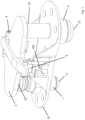
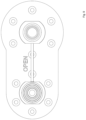
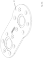
- the closure assembly of the disclosure is provided for a fill port 100 and an overflow port 200 provided in a housing 10'.
- the first end 101 of the fill port and the first end 201 of the overflow are configured to fluidly connect to the storage tank.
- the fittings 110 and 210 at the second ends of the ports are configured to, respectively, fluidly connect to the fill line and the overflow line (not shown) during filling.
- a flow channel 111,211 extends from the fittings, through the port, to the first ends.
- the closure is formed within the fill port as will be described further below, and is activated to open when a fill hose is connected to the port and/or to close when a fill hose is detached from the port.
- the closure comprises a form of ball valve located in the body of the port.
- two ports 100, 200 are provided on a single housing 10' and each has a ball valve closure 150, 250 located within the flow channel 111, 211 between the first end 101, 201 and the second end 110, 210 of the port.
- the ball valve closure 150, 250 is a ball having an open passage 151, 251 extending therethrough, the ball being rotatable relative to the port 100, 200 body such that, when the ball valve closure is in an open position, the passage 151, 251 aligns with the flow channel 111,211 to allow fluid to flow through the port from the fitting to the first end.
- the ball is rotatable relative to the port such that when the ball valve closure is in a closed position, the passage 151, 251 is not aligned with the channel - and, in the embodiment shown, extends through the ball in a direction perpendicular to the channel.
- the ball therefore, is positioned to present a closed face to the flow channel thus blocking flow from the fitting to the first end of the port.
- the port is mounted relative to the housing 10' such that the axis X passes through from one side a of the housing to the other b.
- the first end 101, 201 of the port extends axially from one side a of the housing.
- the second end of the port around which the fitting 110, 210 is provided extends axially from the other side b of the housing.
- a rod 300 is connected at a first end 311 to the ball 150 and extends from the ball out of a side wall of the port.
- a sleeve 400 is mounted around the port exterior to the port around the location where the ball is mounted inside the port.
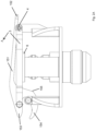
- a spring 500 is provided between the sleeve 400 and the second side b of the housing 10' and axially biases the sleeve away from the housing 10' to a first position (the closed position shown in Fig. 5 ).
- the sleeve 400 includes an aperture or slot 410 through which the rod 300 extends.
- Some form of gear configuration is provided between the sleeve and the rod such that axial movement of the sleeve causes rotation of the rod which, in turn, rotates the ball to which it is connected.
- the aperture or slot 410 is provided with teeth 420 on its inner surface.
- a toothed cog 320 is provided around the rod 300 where it passes through the slot 410.
- the cog 320 has radially outwardly extending teeth that engage with the radially inwardly extending teeth 420 on the inner surface of the slot.
- the cog 320 is fixed to the rod 300 so that the rod and the cog rotate together.
- the rod is fixed to the ball so that rotation of the rod causes rotation of the ball and, hence, rotation of the cog causes rotation of the ball.
- the slot and cog gearing ensures a smooth, linear movement of the sleeve leading to rotation of the ball. Other gearing or geometrical connections may be used to ensure rotation of the rod with linear movement of the sleeve.
- connection between the rod and the ball and the engagement of the teeth of the cog and the teeth of the slot are configured such that when the spring is in its default state, biasing the sleeve 400 away from the housing 10' the rod engages via the engagement of the teeth in a rotational position in which the connected ball is in the closed position as shown in Fig. 5 .
- a hose 700 is pushed onto the fitting 110.
- the sleeve and the spring are arranged such that when the hose is pushed onto the fitting, the hose pushes down against the sleeve which, in turn, pushes against the force of the spring, compressing the spring.
- the engagement of the teeth of the slot and the teeth of the cog causes the cog to rotate. This, in turn, causes rotation of the rod 300 which, in turn, rotates the ball to the open position, as shown in Fig. 7 .
- the interaction between the teeth of the slot and the cog can best be seen in Fig. 8 .
- the spring 500 When the hose 700 is removed, the spring 500 will relax - i.e. expand, thus pushing the sleeve upwards again. The movement of the slot relative to the cog and rod will cause rotation of the cog, and thus the rod and consequently the ball, in the opposite direction, to the closed position.
- the rod 300 is preferably arranged such that it can be manually rotated by a user should the sleeve and spring configuration fail.
- the ball valve closures 150, 250 may be connected by a single common rod 300, one end 311 of which is connected to the ball 150 of the fill port 100, the other end 312 of which is connected to the ball 250 in the overflow port.
- the rod 300 may also be provided with an indicator to indicate, based on the angle of rotation of the rod, whether the ball valve closures are in the open or closed position.
- a tab or flag 301 may be mounted to or extend from the rod in a way such that when the ball valve closures are in the closed state, the tab indicates that the closure is closed by visually presenting, to a user, e.g. the word 'closed' (as seen in e.g. Fig. 6 ), or a colour or other symbol representative of a closed state; when, on the other hand, the closures are open, the indicator will provide an indication of the open state.
- the connecting rod 300 will also ensure that both ball valve closure are open or closed at the same time.
- the overflow port will also automatically open.
- Both the common rod and the indicator are independently, and in combination, optional features.
- Each port could have its own rod.
- a state indicator could be provided, if desired, e.g. by means of an external flag or indicator that is connected to rotate with the ball to provide a different indication depending on whether the closure is closed or open. Again, such an indicator is, however, optional.
- seals e.g. Teflon TM seals 900 may be mounted around the ball within the port.
- the housing 10 of the present disclosure is much simpler and lighter and less machined than the housing 10 of the known design.
- the housing is usually the most expensive part of the assembly, this is clearly advantageous.
- a reduction in mass, number of parts and manufacturing costs and complexity is important in many fields including the aircraft industry.
- the design of the disclosure avoids the need for flaps and hinges and so reduces the adverse effects of wear of those parts.
- the closures internal to the ports and opened automatically on attachment of a hose the opening and closing function requires much less space and the envelope of the assembly is greatly reduced. Furthermore, the assembly can be easily inspected for damage.
Landscapes
- Engineering & Computer Science (AREA)
- General Engineering & Computer Science (AREA)
- Mechanical Engineering (AREA)
- Mechanically-Actuated Valves (AREA)
- Taps Or Cocks (AREA)
Priority Applications (2)
| Application Number | Priority Date | Filing Date | Title |
|---|---|---|---|
| EP23461505.2A EP4407225B1 (de) | 2023-01-26 | 2023-01-26 | Wasseranschlussverschlussanordnung |
| US18/416,251 US12552658B2 (en) | 2023-01-26 | 2024-01-18 | Water port closure assembly |
Applications Claiming Priority (1)
| Application Number | Priority Date | Filing Date | Title |
|---|---|---|---|
| EP23461505.2A EP4407225B1 (de) | 2023-01-26 | 2023-01-26 | Wasseranschlussverschlussanordnung |
Publications (2)
| Publication Number | Publication Date |
|---|---|
| EP4407225A1 true EP4407225A1 (de) | 2024-07-31 |
| EP4407225B1 EP4407225B1 (de) | 2025-12-10 |
Family
ID=85132819
Family Applications (1)
| Application Number | Title | Priority Date | Filing Date |
|---|---|---|---|
| EP23461505.2A Active EP4407225B1 (de) | 2023-01-26 | 2023-01-26 | Wasseranschlussverschlussanordnung |
Country Status (2)
| Country | Link |
|---|---|
| US (1) | US12552658B2 (de) |
| EP (1) | EP4407225B1 (de) |
Families Citing this family (1)
| Publication number | Priority date | Publication date | Assignee | Title |
|---|---|---|---|---|
| EP4495471A1 (de) * | 2023-07-20 | 2025-01-22 | Goodrich Corporation | Wasseranschlussverschlussanordnung |
Citations (5)
| Publication number | Priority date | Publication date | Assignee | Title |
|---|---|---|---|---|
| US3423063A (en) * | 1966-10-19 | 1969-01-21 | Aro Corp | Valved safety speed coupler |
| US4422618A (en) * | 1981-12-01 | 1983-12-27 | Armco Inc. | Remotely operated valve |
| US4445664A (en) * | 1981-10-26 | 1984-05-01 | Aeroquip Corporation | Axial force operated ball valve |
| US4928731A (en) * | 1989-06-22 | 1990-05-29 | Auto-Valve, Inc. | Aircraft toilet tank filling valve assembly |
| US20220290766A1 (en) * | 2019-03-03 | 2022-09-15 | California Controlled Atmosphere | Switching assembly for pressure relief valves |
Family Cites Families (9)
| Publication number | Priority date | Publication date | Assignee | Title |
|---|---|---|---|---|
| US246538A (en) * | 1881-08-30 | James mtjllaney | ||
| US3116755A (en) * | 1961-09-06 | 1964-01-07 | Andale Co | Means for simultaneously actuating plug valves in a duplex strainer |
| US5462086A (en) * | 1994-11-07 | 1995-10-31 | Taylor; Julian S. | Selector relief valve assembly |
| NL1014456C2 (nl) * | 2000-02-21 | 2001-08-22 | Indufil B V | Uit een stel schakelkranen opgebouwde schakeleenheid geschikt om een eerste en een tweede medium naar keuze door ÚÚn van twee platenkoelers te doen stromen. |
| US6206028B1 (en) * | 2000-06-19 | 2001-03-27 | The Keeney Manufacturing Company | Universal multi-path control valve system |
| US6672280B2 (en) * | 2001-03-09 | 2004-01-06 | Visteon Global Technologies, Inc. | Torsion spring assembly for electronic throttle |
| US7201003B2 (en) * | 2004-03-11 | 2007-04-10 | General Electric Company | Magnet vent assembly apparatus |
| DE102004035854B4 (de) | 2004-07-23 | 2007-11-22 | Airbus Deutschland Gmbh | Adapter zum Kuppeln von zwei Verbindungsleitungen |
| US9273449B2 (en) | 2012-10-04 | 2016-03-01 | B/E Aerospace, Inc. | Aircraft galley water distribution manifold |
-
2023
- 2023-01-26 EP EP23461505.2A patent/EP4407225B1/de active Active
-
2024
- 2024-01-18 US US18/416,251 patent/US12552658B2/en active Active
Patent Citations (5)
| Publication number | Priority date | Publication date | Assignee | Title |
|---|---|---|---|---|
| US3423063A (en) * | 1966-10-19 | 1969-01-21 | Aro Corp | Valved safety speed coupler |
| US4445664A (en) * | 1981-10-26 | 1984-05-01 | Aeroquip Corporation | Axial force operated ball valve |
| US4422618A (en) * | 1981-12-01 | 1983-12-27 | Armco Inc. | Remotely operated valve |
| US4928731A (en) * | 1989-06-22 | 1990-05-29 | Auto-Valve, Inc. | Aircraft toilet tank filling valve assembly |
| US20220290766A1 (en) * | 2019-03-03 | 2022-09-15 | California Controlled Atmosphere | Switching assembly for pressure relief valves |
Also Published As
| Publication number | Publication date |
|---|---|
| US20240253969A1 (en) | 2024-08-01 |
| US12552658B2 (en) | 2026-02-17 |
| EP4407225B1 (de) | 2025-12-10 |
Similar Documents
| Publication | Publication Date | Title |
|---|---|---|
| US4634098A (en) | Ball Valve | |
| EP0156574B1 (de) | Drehschieber Betätigungsmechanismus | |
| US3987812A (en) | Adapter valve | |
| US12552658B2 (en) | Water port closure assembly | |
| JPH0796959A (ja) | 短いパイプの注ぎ口を密閉するための密閉蓋 | |
| US10436335B2 (en) | Valves with multi-directional ball check | |
| US4690296A (en) | Open flow valve assembly | |
| JP4262833B2 (ja) | 保護ケース入り袋の弁装置 | |
| US5609185A (en) | Valve indicator and handle assembly | |
| US3086565A (en) | Servicing nozzle | |
| US5090658A (en) | Bellows sealed rotary valve and seal assembly | |
| US4871303A (en) | Fuel drain safety system for fuel pumps and the like | |
| US8251086B2 (en) | Rotary gate valve with secondary seal | |
| EP4495471A1 (de) | Wasseranschlussverschlussanordnung | |
| US4526194A (en) | Tamper-proof valve | |
| EP0489296A1 (de) | Kugelhahn mit Durchflusssteueranordnung | |
| US12292150B2 (en) | Water port closure assembly | |
| US12441536B2 (en) | Water port closure assembly | |
| US3703189A (en) | Drain valve | |
| US2512052A (en) | Drain valve | |
| US20240183451A1 (en) | Hydraulic valve | |
| EP2347157B1 (de) | Griffwellenanordnungen für von unten beladbare koppler | |
| EP0159799A2 (de) | Kugelhahn | |
| US20230406507A1 (en) | Discharge valve for an aircraft and associated method | |
| US5540413A (en) | Aircraft pressure-fueling nozzle |
Legal Events
| Date | Code | Title | Description |
|---|---|---|---|
| PUAI | Public reference made under article 153(3) epc to a published international application that has entered the european phase |
Free format text: ORIGINAL CODE: 0009012 |
|
| STAA | Information on the status of an ep patent application or granted ep patent |
Free format text: STATUS: THE APPLICATION HAS BEEN PUBLISHED |
|
| AK | Designated contracting states |
Kind code of ref document: A1 Designated state(s): AL AT BE BG CH CY CZ DE DK EE ES FI FR GB GR HR HU IE IS IT LI LT LU LV MC ME MK MT NL NO PL PT RO RS SE SI SK SM TR |
|
| STAA | Information on the status of an ep patent application or granted ep patent |
Free format text: STATUS: REQUEST FOR EXAMINATION WAS MADE |
|
| 17P | Request for examination filed |
Effective date: 20250129 |
|
| GRAP | Despatch of communication of intention to grant a patent |
Free format text: ORIGINAL CODE: EPIDOSNIGR1 |
|
| STAA | Information on the status of an ep patent application or granted ep patent |
Free format text: STATUS: GRANT OF PATENT IS INTENDED |
|
| INTG | Intention to grant announced |
Effective date: 20250714 |
|
| GRAS | Grant fee paid |
Free format text: ORIGINAL CODE: EPIDOSNIGR3 |
|
| GRAA | (expected) grant |
Free format text: ORIGINAL CODE: 0009210 |
|
| STAA | Information on the status of an ep patent application or granted ep patent |
Free format text: STATUS: THE PATENT HAS BEEN GRANTED |
|
| AK | Designated contracting states |
Kind code of ref document: B1 Designated state(s): AL AT BE BG CH CY CZ DE DK EE ES FI FR GB GR HR HU IE IS IT LI LT LU LV MC ME MK MT NL NO PL PT RO RS SE SI SK SM TR |
|
| REG | Reference to a national code |
Ref country code: CH Ref legal event code: F10 Free format text: ST27 STATUS EVENT CODE: U-0-0-F10-F00 (AS PROVIDED BY THE NATIONAL OFFICE) Effective date: 20251210 Ref country code: GB Ref legal event code: FG4D |
|
| REG | Reference to a national code |
Ref country code: DE Ref legal event code: R096 Ref document number: 602023009546 Country of ref document: DE |
|
| REG | Reference to a national code |
Ref country code: IE Ref legal event code: FG4D |
|
| PG25 | Lapsed in a contracting state [announced via postgrant information from national office to epo] |
Ref country code: ES Free format text: LAPSE BECAUSE OF FAILURE TO SUBMIT A TRANSLATION OF THE DESCRIPTION OR TO PAY THE FEE WITHIN THE PRESCRIBED TIME-LIMIT Effective date: 20251210 |
|
| REG | Reference to a national code |
Ref country code: LT Ref legal event code: MG9D |
|
| PG25 | Lapsed in a contracting state [announced via postgrant information from national office to epo] |
Ref country code: NO Free format text: LAPSE BECAUSE OF FAILURE TO SUBMIT A TRANSLATION OF THE DESCRIPTION OR TO PAY THE FEE WITHIN THE PRESCRIBED TIME-LIMIT Effective date: 20260310 |
|
| PGFP | Annual fee paid to national office [announced via postgrant information from national office to epo] |
Ref country code: DE Payment date: 20251217 Year of fee payment: 4 |
|
| PG25 | Lapsed in a contracting state [announced via postgrant information from national office to epo] |
Ref country code: FI Free format text: LAPSE BECAUSE OF FAILURE TO SUBMIT A TRANSLATION OF THE DESCRIPTION OR TO PAY THE FEE WITHIN THE PRESCRIBED TIME-LIMIT Effective date: 20251210 Ref country code: HR Free format text: LAPSE BECAUSE OF FAILURE TO SUBMIT A TRANSLATION OF THE DESCRIPTION OR TO PAY THE FEE WITHIN THE PRESCRIBED TIME-LIMIT Effective date: 20251210 |
|
| PGFP | Annual fee paid to national office [announced via postgrant information from national office to epo] |
Ref country code: AT Payment date: 20260301 Year of fee payment: 4 |
|
| REG | Reference to a national code |
Ref country code: NL Ref legal event code: MP Effective date: 20251210 |
|
| PG25 | Lapsed in a contracting state [announced via postgrant information from national office to epo] |
Ref country code: RS Free format text: LAPSE BECAUSE OF FAILURE TO SUBMIT A TRANSLATION OF THE DESCRIPTION OR TO PAY THE FEE WITHIN THE PRESCRIBED TIME-LIMIT Effective date: 20260310 |
|
| PGFP | Annual fee paid to national office [announced via postgrant information from national office to epo] |
Ref country code: FR Payment date: 20260121 Year of fee payment: 4 |
|
| PG25 | Lapsed in a contracting state [announced via postgrant information from national office to epo] |
Ref country code: LV Free format text: LAPSE BECAUSE OF FAILURE TO SUBMIT A TRANSLATION OF THE DESCRIPTION OR TO PAY THE FEE WITHIN THE PRESCRIBED TIME-LIMIT Effective date: 20251210 |