EP4407322A2 - Ensemble aimant de jante permettant de fixer un aimant sur une jante au moyen d'une tige d'une soupape - Google Patents
Ensemble aimant de jante permettant de fixer un aimant sur une jante au moyen d'une tige d'une soupape Download PDFInfo
- Publication number
- EP4407322A2 EP4407322A2 EP24176735.9A EP24176735A EP4407322A2 EP 4407322 A2 EP4407322 A2 EP 4407322A2 EP 24176735 A EP24176735 A EP 24176735A EP 4407322 A2 EP4407322 A2 EP 4407322A2
- Authority
- EP
- European Patent Office
- Prior art keywords
- magnet
- rim
- housing
- shaft
- valve
- Prior art date
- Legal status (The legal status is an assumption and is not a legal conclusion. Google has not performed a legal analysis and makes no representation as to the accuracy of the status listed.)
- Granted
Links
Images


Classifications
-
- B—PERFORMING OPERATIONS; TRANSPORTING
- B60—VEHICLES IN GENERAL
- B60C—VEHICLE TYRES; TYRE INFLATION; TYRE CHANGING; CONNECTING VALVES TO INFLATABLE ELASTIC BODIES IN GENERAL; DEVICES OR ARRANGEMENTS RELATED TO TYRES
- B60C29/00—Arrangements of tyre-inflating valves to tyres or rims; Accessories for tyre-inflating valves, not otherwise provided for
- B60C29/02—Connection to rims
-
- B—PERFORMING OPERATIONS; TRANSPORTING
- B62—LAND VEHICLES FOR TRAVELLING OTHERWISE THAN ON RAILS
- B62J—CYCLE SADDLES OR SEATS; AUXILIARY DEVICES OR ACCESSORIES SPECIALLY ADAPTED TO CYCLES AND NOT OTHERWISE PROVIDED FOR, e.g. ARTICLE CARRIERS OR CYCLE PROTECTORS
- B62J45/00—Electrical equipment arrangements specially adapted for use as accessories on cycles, not otherwise provided for
- B62J45/40—Sensor arrangements; Mounting thereof
- B62J45/41—Sensor arrangements; Mounting thereof characterised by the type of sensor
- B62J45/412—Speed sensors
-
- B—PERFORMING OPERATIONS; TRANSPORTING
- B62—LAND VEHICLES FOR TRAVELLING OTHERWISE THAN ON RAILS
- B62J—CYCLE SADDLES OR SEATS; AUXILIARY DEVICES OR ACCESSORIES SPECIALLY ADAPTED TO CYCLES AND NOT OTHERWISE PROVIDED FOR, e.g. ARTICLE CARRIERS OR CYCLE PROTECTORS
- B62J45/00—Electrical equipment arrangements specially adapted for use as accessories on cycles, not otherwise provided for
- B62J45/40—Sensor arrangements; Mounting thereof
- B62J45/42—Sensor arrangements; Mounting thereof characterised by mounting
- B62J45/423—Sensor arrangements; Mounting thereof characterised by mounting on or besides the wheel
-
- G—PHYSICS
- G01—MEASURING; TESTING
- G01P—MEASURING LINEAR OR ANGULAR SPEED, ACCELERATION, DECELERATION, OR SHOCK; INDICATING PRESENCE, ABSENCE, OR DIRECTION, OF MOVEMENT
- G01P3/00—Measuring linear or angular speed; Measuring differences of linear or angular speeds
- G01P3/42—Devices characterised by the use of electric or magnetic means
- G01P3/44—Devices characterised by the use of electric or magnetic means for measuring angular speed
- G01P3/48—Devices characterised by the use of electric or magnetic means for measuring angular speed by measuring frequency of generated current or voltage
- G01P3/481—Devices characterised by the use of electric or magnetic means for measuring angular speed by measuring frequency of generated current or voltage of pulse signals
- G01P3/487—Devices characterised by the use of electric or magnetic means for measuring angular speed by measuring frequency of generated current or voltage of pulse signals delivered by rotating magnets
Definitions
- the invention relates to a rim magnet arrangement for fixing a magnet to a rim by means of a shaft of a valve, comprising a magnet arranged in a housing.
- the invention further relates to a rim assembly for a bicycle or the like, comprising a rim magnet assembly and a rim.
- the invention further relates to a method for producing a rim magnet arrangement.
- a pulse generator in the form of a magnet to a spoke and to detect the respective rotation of the magnet on the wheel using a magnetic field sensor that is arranged on a part of the frame of the bicycle.
- the speed of the bicycle can be determined based on the time difference between two consecutive passages of the magnet and the circumference of the tire, which can be determined, for example, from the EN 10 2017 212 924 A1 has become known.
- the present invention provides a rim assembly for a bicycle or the like, comprising a rim magnet assembly as described above and a rim, wherein the magnet is axially and rotationally fixed to the rim by means of the fixing device and the anti-twist device.
- the present invention provides a method of manufacturing a rim magnet assembly as described above, wherein the housing is manufactured by means of a two-component injection molding process.
- One of the advantages achieved is a simple and reliable attachment of a magnet to a rim using the valve shaft. Another advantage is that the magnet can be attached to a variety of different rims. Another advantage is a particularly reliable detection of the driving speed of a magnet attached to a rim using the rim magnet arrangement.
- the magnet can in particular be designed as a permanent magnet.
- the magnet is arranged in a housing, in particular made of plastic.
- the advantage of this is that the magnet is protected from environmental influences.
- the fixing device has a screw device that can be screwed onto the shaft of the valve. This enables the magnet to be reliably and detachably fixed to a rim.
- the housing has at least one spring-elastic element which is designed to protrude from the housing in the axial direction of the shaft and in particular is designed to partially taper inwards towards the middle of the housing.
- This can generate a preload in the axial direction, which enables a particularly reliable attachment to the valve. If, for example, the tire pressure drops, the valve protrudes further from the rim. This can be compensated by means of the preload.
- the at least one spring-elastic element can also provide an anti-twisting device in that it at least partially rests positively on the rim.
- At least two, in particular four spring-elastic elements are arranged, which are arranged symmetrically on the housing and in particular are designed identically. This makes it possible to provide a particularly high preload and a particularly secure anti-twisting device.
- the anti-twisting device comprises a molded sleeve which has at least one recess or projection and which engages in a corresponding projection or recess of the magnet and/or its housing.
- the molded sleeve is designed to be self-locking.
- the anti-twisting device is formed by an adhesive applied to the magnet and/or its housing, in particular in the form of a double-sided adhesive tape. This enables the magnet to be attached to the valve shaft particularly quickly and easily.
- the anti-twisting device comprises a clamp with a U-shaped cross-sectional profile, which can be fixed to the shaft and is designed to be fixed in the fixed state of the magnet by means of Form-fit with the magnet and/or with the housing on the one hand and at least partially with a rim on the other hand to prevent rotation.
- a clamp with a U-shaped cross-sectional profile which can be fixed to the shaft and is designed to be fixed in the fixed state of the magnet by means of Form-fit with the magnet and/or with the housing on the one hand and at least partially with a rim on the other hand to prevent rotation.
- the anti-twisting device comprises a bore with an undersize in relation to the diameter of the shaft in the housing of the magnet.
- the anti-twisting device has at least one friction-increasing element. This provides a particularly reliable anti-twisting device.
- the anti-twist device comprises a press sleeve which is arranged on the shaft of the valve.
- the press sleeve can preferably be made of rubber.
- the advantage of this is a simple anti-twist device provided by deformation.
- a sleeve can also be arranged together with the press sleeve, in particular above it, on the shaft of the valve.
- the anti-twisting device is provided by elastic material of the magnet housing.
- the magnet is formed in one piece and the magnet and in particular the housing have a central bore corresponding to one another for fastening on the shaft of the valve.
- the magnet and its housing can thus be simply placed on the shaft of the housing and secured by means of the fastening device.
- the magnet is designed in two parts and a receiving device is arranged for the two parts of the magnet in the housing.
- the magnet is arranged such that it provides a magnetic field perpendicular to the axial direction of the shaft of the valve or parallel to its axial direction. This provides reliable detection of the magnetic field of the magnet, in particular when the magnetic field is aligned perpendicular to the axial direction of the shaft of the valve.
- Figure 1 shows a partial side view of a bicycle in the area of the bicycle drive.
- a bicycle 60 is shown in the area of the drive 61.
- This has a magnetic field sensor 62, integrated in the drive 61, in a known manner.
- a rim arrangement 50 with rim magnet arrangement 1 is shown with a rim 8, which has a valve 3.
- the valve 3 has a valve stem 2, onto which a magnet 4 arranged in a housing 5 is placed.
- the housing 5 and magnet 4 have a central bore 20 for this purpose.
- the housing 5 rests on its underside on the rim 8 of the bicycle 60. Both are then secured to the stem 2 of the valve 3 by means of a mounting nut 10.
- the magnet 4 provides a magnetic field 200, which can be measured by the magnetic field sensor 62.
- Figure 2a shows a rim magnet arrangement according to an embodiment of the present invention.
- a rectangular magnet 4 is shown arranged in a substantially rectangular housing 5.
- the housing has a structural anti-twist protection.
- the anti-twist protection is formed here by flexible or elastic fins 11, which can adapt to the respective rim shape and are designed to protrude in the axial direction of the shaft 2 and partially protrude inwards in the radial direction.
- a second function of the elastic fins 11 is to apply a preload, which then inhibits the assembly nut 10 and prevents the magnet 4 with the housing 5 from coming loose during operation.
- Figure 2b shows a rim assembly according to an embodiment of the present invention.
- the magnet 4, together with the housing 5, mounted by means of a fixing device 6 is shown fixed to the shaft 2 of a valve 3.
- the magnet 4 is first pushed over the valve 3, more precisely the shaft 2 of the valve 3 in the axial direction 100 of the shaft 2, until the flexible fins 11 touch the rim 8.
- the component, i.e. magnet 4 and its housing 5, have an opening or bore 20, which has the diameter of the largest valve shaft diameter to be covered, for example that of the Schrader valve.
- a compensating sleeve 22 can be inserted between the shaft 2 and the bore 20 of the component 4, 5, as shown here.
- the valve nut 10 is then screwed onto the valve 3 until it rests on the compensating sleeve 22.
- the valve nut 10 now presses the component onto the rim 8 via the compensating sleeve 22.
- the flexible fins 11 are pressed onto the flanks of the rim 8 and partially adapt to the shape of the rim 8.
- the valve nut 10 is now tightened further, in particular by hand.
- the valve nut 10 of the fastening device 6 now presses the compensating sleeve 22 onto the housing 5 of the magnet 4. Since the flexible fins 11 have a certain rigidity, this system is now pre-tensioned. The principle corresponds to that of a leaf spring. The wider the rim 8 and the more acute the flank angle of the rim 8, the more preload force is generated, as the fins 11 are pushed further apart. An additional preload force can already be specified structurally by making the fins 11 in the unloaded state already tapered inwards towards the middle of the component 4, 5 as in the Figures 2a and 2b shown.
- This preload prevents the magnet 4 from twisting laterally in the circumferential direction 101 of the shaft 2. Since the preload force acts in particular between the valve nut 10 and component 4, 5, it also prevents the valve nut 10 from loosening at the frictional connection. In particular, pressure fluctuations in the tire on the rim 8 lead to a change in the preload force. For example, inflating the tire or tube causes the valve 3 to be pushed further out of the rim 8 and the preload force decreases. The preload force provided by the fins 11 is so great that sufficient anti-twisting protection and sufficient inhibiting effect on the valve nut 10 is ensured even in the event of pressure fluctuations.
- the preload force required for the application can be adjusted by selecting the material in terms of elasticity and the material thickness of the fins 11 when designing the component 4, 5. Effective anti-twisting protection is provided by at least two fins 11, but there can also be more, for example four fins 11 as shown.
- an O-ring is often used, which is inserted between the rim 8 and the valve nut 10.
- a A recessed groove is formed which accommodates the O-ring. In this way, the underside of the component 4, 5 can continue to rest on the rim 8 without an air gap.
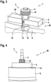
- Figure 3 shows a rim assembly according to an embodiment of the present invention.
- Figure 4 shows a rim assembly according to an embodiment of the present invention.
- a double-sided adhesive tape 15 is applied to the left and right of the central hole 20 on the side of the housing 5 of the magnet 4 facing the rim 8.
- the component 4, 5 is then placed on the shaft 2 of the valve 3 and pressed onto the adhesive tape 15.
- the component 4, 5 is then firmly screwed on using the valve nut 10.
- the adhesive tape 15 also prevents the component 4, 5, in particular the magnet 4, from lifting off if the valve nut 10 comes loose on the rim 8 due to pressure fluctuations in the tire.
- Figure 5 shows a rim assembly according to an embodiment of the present invention and Figure 6 a rim arrangement according to Figure 5 in cross section.
- a rim arrangement 50 is shown with an anti-twisting device 7 in the form of a securing clip 16.
- This safety clip 16 which is partially flexible, is placed on the shaft 2 of the valve 3 via a hole 16a.
- the component 4, 5 with a central hole 20 is placed over this and pressed firmly onto the rim 8.
- the component 4, 5 is then screwed tightly using the valve nut 10.
- the shape of the safety clip 16 is designed such that it does not adapt to the shape of the rim 8 or bend when it is placed on the rim 8 without load. Only when the safety clip 16 is subjected to a contact force is the safety clip 16 pressed apart and partially adapts to the shape of the rim 8.
- the material of the safety clip 16 is selected such that the safety clip 16 acts as a spring when pressed onto the rim 8.
- the shape of the locking clip 16 is reproduced as a negative form in the housing 5 of the magnet 4, so that with the corresponding contact force a positive connection 30 is provided between the locking clip 16 and the housing 5.
- an anti-twisting device 7 is now ensured.
- the system described is braced against the valve nut 10, which ensures that pressure fluctuations are compensated and prevents the valve nut 10 from coming loose.
- Figure 7a, 7b , 7c shows a rim arrangement according to an embodiment of the present invention.
- a component 4, 5 is shown in the form of a monomagnet.
- the monomagnet 4, 5 comprises two components, a monolithic magnet block 4 and a plastic overmold 5.
- the monomagnet 4, 5 has a hole or bore 20 in the middle.
- the monomagnet 4, 5 can be cut lengthwise or in Figure 7c shown with magnetic field direction 200, as well as in height, according to Figure 7b , i.e. perpendicular to the Figure 7c shown direction - magnetic field direction 200 - polarized.
- a component 4, 5 is shown, wherein the magnet 4 is formed in two parts with two parts 4a, 4b.
- the two parts 4a, 4b are arranged so that these have a common magnetic field direction 200 - here perpendicular to the axis of the shaft 2 of the valve 3.
- the two parts 4a, 4b are directly overmolded with the overmold 5 and not separately in a holder as in Figure 9 arranged.
- the overmolding 5 protects the magnet 4 from weather influences and excessive stress.
- the anti-twist device 7 can be designed analogously to the embodiment of the Figures 2a, 2b by flexible or elastic fins 11, which adapt to the shape of the rim.
- a second function of the elastic fins 11 is, as already explained, to apply a preload that inhibits the valve nut 10 and prevents the component 4, 5 from coming loose during operation.
- the material of the overmolding 5 is selected in particular so that it has enough strength to absorb the forces of the valve nut 10 and has enough flexibility so that the side fins 11 can adapt to any rim shape.
- a possible advantage of this embodiment is that the magnet 4 and the component 4, 5 can be designed to be very simple, slim and unobtrusive.
- Figure 8 shows a rim magnet arrangement according to an embodiment of the present invention and Figure 9 a rim assembly according to an embodiment of the present invention.
- a component 4, 5 which has two identical individual magnets 4a, 4b, which are mounted in a common holder 21 within a housing 5, which is formed by overmolding the two magnets 4a, 4b, according to the embodiment of the Figures 2a and 2b
- the individual magnets 4a, 4b can serve as signal transmitters.
- the individual magnets 4a, 4b can be arranged both lengthwise and in Figure 9 shown with magnetic field direction 200, as well as in height, i.e. perpendicular to the Figure 9 shown direction in the plane of the drawing of the Figure 9 polarized.
- the holder or holding basket 21 has two functions.
- the Finns 11 represent the in the description of the Figures 2a, 2b described preload force and anti-twisting device.
- the anti-twisting device 7 is realized by increasing the coefficient of friction between the magnet 4 or the housing 5 and the rim 8.
- Figure 10 shows a rim assembly according to an embodiment of the present invention.
- a rim arrangement 50 is shown which is arranged between two adjacent spokes 90 of a wheel.
- One or more so-called “friction shims”, i.e. friction disks 17, are arranged between the housing underside of the component 4, 5 or, if the magnet 4 does not have a housing, between the underside of the magnet 4 and the rim 8.
- These friction shims 17 are designed in such a way that their diameter is adapted to the Sclaverand and Schrader valves and that they form the contact surface of the magnet 4 or its housing 5 in the immediate vicinity of the bore 20.
- the disk or disks 17 are placed over the shaft 2 of the valve 3.
- the component 4, 5 is then placed over it and then the valve nut 10 is screwed onto the shaft 2 of the valve 3 and tightened.
- Micro-form closures occur between the friction disc 17 and the housing 5 and between the friction disc 17 and the rim 8. This means that the coefficient of friction can be at least doubled and an anti-twisting device 7 is ensured.
- Figure 11 shows a rim assembly according to an embodiment of the present invention.
- the anti-twisting device 7 is created by a rubber sleeve 23, which is pressed and thereby presses itself between the valve thread and the wall of the bore 20 of the component 4, 5.
- the Rubber sleeve 23 is put over the shaft 2 of the valve 3.
- the component 4, 5 is put on the rubber sleeve 23 and pressed onto the rim 8.
- another sleeve 22 made of inelastic material is inserted into the bore 20 of the component 4, 5 until it rests on the rubber sleeve 23.
- the valve nut 10 is screwed onto the shaft 2 of the valve 3 and tightened until the inelastic sleeve 22 with the collar rests on the component 4, 5. This deforms the rubber sleeve 23 so much that it is pressed between the valve thread and the wall of the bore 20 (reference number 24). This ensures that the valve is protected against rotation 7.
- Figure 12 shows a rim assembly according to an embodiment of the present invention.
- the anti-twisting device 7 is created by the material of the housing 5 of the magnet 4.
- the magnet 4 is overmolded with an elastomer 5a, which has a high coefficient of friction and is at least partially deformed.
- the design of the overmold 5a is selected so that the overmold 5a on the underside of the component 4, 5 is deformed and tensioned when screwed onto the shaft 2 of the valve 3.
- the overmolding 5a is not flat in relation to the surface of the rim 8, but is selected such that when the overmolding 5a is placed, cavities 58 are formed between the housing 5 and the rim 8.
- the elastomer When screwed, the elastomer deforms and the cavities 58 are filled by the elastomer. The force thus generated clamps the component 4, 5 against the valve nut 10. In conjunction with the increased coefficient of friction between the elastomer and, for example, an aluminum rim, the anti-twisting device 7 is ensured. In addition, the system is clamped against the valve screw 10, which makes the system less susceptible to pressure fluctuations.
Landscapes
- Engineering & Computer Science (AREA)
- Mechanical Engineering (AREA)
- Physics & Mathematics (AREA)
- General Physics & Mathematics (AREA)
- Valve Housings (AREA)
- Permanent Field Magnets Of Synchronous Machinery (AREA)
- Magnetically Actuated Valves (AREA)
Applications Claiming Priority (2)
| Application Number | Priority Date | Filing Date | Title |
|---|---|---|---|
| DE102021209110.5A DE102021209110A1 (de) | 2021-08-19 | 2021-08-19 | Felgenmagnetanordnung zur Festlegung eines Magneten an einer Felge mittels eines Schafts eines Ventils |
| EP22183817.0A EP4137394B1 (fr) | 2021-08-19 | 2022-07-08 | Agencement d'aimant de jante destiné à la fixation d'un aimant à une jante au moyen d'une tige d'une soupape |
Related Parent Applications (1)
| Application Number | Title | Priority Date | Filing Date |
|---|---|---|---|
| EP22183817.0A Division EP4137394B1 (fr) | 2021-08-19 | 2022-07-08 | Agencement d'aimant de jante destiné à la fixation d'un aimant à une jante au moyen d'une tige d'une soupape |
Publications (3)
| Publication Number | Publication Date |
|---|---|
| EP4407322A2 true EP4407322A2 (fr) | 2024-07-31 |
| EP4407322A3 EP4407322A3 (fr) | 2024-10-09 |
| EP4407322B1 EP4407322B1 (fr) | 2025-09-10 |
Family
ID=82403929
Family Applications (2)
| Application Number | Title | Priority Date | Filing Date |
|---|---|---|---|
| EP22183817.0A Active EP4137394B1 (fr) | 2021-08-19 | 2022-07-08 | Agencement d'aimant de jante destiné à la fixation d'un aimant à une jante au moyen d'une tige d'une soupape |
| EP24176735.9A Active EP4407322B1 (fr) | 2021-08-19 | 2022-07-08 | Ensemble aimant de jante permettant de fixer un aimant sur une jante au moyen d'une tige d'une soupape |
Family Applications Before (1)
| Application Number | Title | Priority Date | Filing Date |
|---|---|---|---|
| EP22183817.0A Active EP4137394B1 (fr) | 2021-08-19 | 2022-07-08 | Agencement d'aimant de jante destiné à la fixation d'un aimant à une jante au moyen d'une tige d'une soupape |
Country Status (4)
| Country | Link |
|---|---|
| US (1) | US12103626B2 (fr) |
| EP (2) | EP4137394B1 (fr) |
| CN (1) | CN115871373A (fr) |
| DE (1) | DE102021209110A1 (fr) |
Families Citing this family (1)
| Publication number | Priority date | Publication date | Assignee | Title |
|---|---|---|---|---|
| EP4501767A1 (fr) | 2023-08-01 | 2025-02-05 | DT Swiss AG | Bicyclette et composant de roue pour bicyclette |
Citations (1)
| Publication number | Priority date | Publication date | Assignee | Title |
|---|---|---|---|---|
| DE102017212924A1 (de) | 2017-07-27 | 2019-01-31 | Robert Bosch Gmbh | Verfahren und Vorrichtung zur Erfassung einer Drehgeschwindigkeit eines Rades eines Zweirads |
Family Cites Families (16)
| Publication number | Priority date | Publication date | Assignee | Title |
|---|---|---|---|---|
| JPH0642208Y2 (ja) | 1989-11-15 | 1994-11-02 | 株式会社キャットアイ | センサマグネット取付装置 |
| US6854335B1 (en) * | 2003-12-12 | 2005-02-15 | Mlho, Inc. | Magnetically coupled tire pressure sensing system |
| DE202004013524U1 (de) | 2004-08-27 | 2004-10-28 | Cycle Parts Gmbh | Magnetischer Impulsgeber |
| US7490700B2 (en) * | 2005-06-02 | 2009-02-17 | Shimano Inc. | Bicycle motion sensing arrangement |
| CA2545839C (fr) | 2006-05-01 | 2010-07-13 | Scott K. Perry | Capuchon antipoussiere magnetique |
| DE202007001665U1 (de) | 2007-01-31 | 2007-09-27 | Reichel, Sven | Magnetischer Ventildeckel an Fahrrädern |
| DE102010042808A1 (de) | 2010-10-22 | 2012-04-26 | Momes Gmbh | Vorrichtung zur Drehzahlerfassung an einem Fahrzeugrad |
| DE202016003819U1 (de) | 2016-06-17 | 2016-06-30 | lryna Shovkoplyas | Fahrradtachometer |
| DE102017212903A1 (de) * | 2017-07-27 | 2019-01-31 | Robert Bosch Gmbh | Verfahren und Vorrichtung zur Überwachung der Bewegung eines Rades eines Zweirads |
| DE102018210754A1 (de) * | 2018-06-29 | 2019-07-04 | Robert Bosch Gmbh | Verfahren und Vorrichtung zur Fehleranalyse einer Geschwindigkeitserfassung |
| DE102018211282A1 (de) | 2018-07-09 | 2020-01-09 | Robert Bosch Gmbh | Verfahren und Vorrichtung zur Fehleranalyse einer Geschwindigkeitserfassung |
| US10675929B1 (en) * | 2018-09-25 | 2020-06-09 | Enrique J. Baiz | Tire valve stem cover |
| US20210140549A1 (en) * | 2019-03-25 | 2021-05-13 | Pacific Industrial Co., Ltd. | Valve |
| DE202019103956U1 (de) | 2019-07-17 | 2020-10-20 | Sks Metaplast Scheffer-Klute Gmbh | Vorrichtung zur Messung eines Drucks eines Zweiradreifens, insbesondere eines Fahrradreifens |
| EP3851298A1 (fr) * | 2020-01-20 | 2021-07-21 | Dana Motion Systems Italia S.R.L. | Ensemble soupape et système de gonflage de pneumatiques |
| IT202000018217A1 (it) * | 2020-07-28 | 2022-01-28 | Campagnolo Srl | Assieme di attacco raggio per una ruota a raggi per bicicletta, relativa ruota e procedimento finalizzato alla realizzazione di tale ruota |
-
2021
- 2021-08-19 DE DE102021209110.5A patent/DE102021209110A1/de active Pending
-
2022
- 2022-07-08 EP EP22183817.0A patent/EP4137394B1/fr active Active
- 2022-07-08 EP EP24176735.9A patent/EP4407322B1/fr active Active
- 2022-08-08 US US17/882,685 patent/US12103626B2/en active Active
- 2022-08-19 CN CN202210997337.9A patent/CN115871373A/zh active Pending
Patent Citations (1)
| Publication number | Priority date | Publication date | Assignee | Title |
|---|---|---|---|---|
| DE102017212924A1 (de) | 2017-07-27 | 2019-01-31 | Robert Bosch Gmbh | Verfahren und Vorrichtung zur Erfassung einer Drehgeschwindigkeit eines Rades eines Zweirads |
Also Published As
| Publication number | Publication date |
|---|---|
| EP4407322A3 (fr) | 2024-10-09 |
| DE102021209110A1 (de) | 2023-02-23 |
| EP4407322B1 (fr) | 2025-09-10 |
| US12103626B2 (en) | 2024-10-01 |
| EP4137394B1 (fr) | 2024-06-12 |
| CN115871373A (zh) | 2023-03-31 |
| US20230056129A1 (en) | 2023-02-23 |
| EP4137394A1 (fr) | 2023-02-22 |
Similar Documents
| Publication | Publication Date | Title |
|---|---|---|
| EP3215750B1 (fr) | Élément de fixation et système de fixation | |
| EP2943798B1 (fr) | Dispositif de détection servant à mesurer la vitesse de rotation d'une roue de véhicule, système de freinage de véhicule et véhicule équipé de ce dispositif, et utilisation du dispositif de détection pour mesurer la vitesse de rotation d'une roue de véhicule | |
| DE2644459B2 (de) | Anordnung zum Abdichten von Reifenventilen bei Fahrzeugen mit geteilten Felgen | |
| DE68908011T2 (de) | Mit einem Pulsgenerator und Sensor ausgestattete nichtangetriebene Kraftfahrzeugnabe, um die Drehzahl des Rades zu messen. | |
| DE102005035183B4 (de) | Anpassbare Montage einer Reifenüberwachungsanordnung | |
| DE102012007996A1 (de) | Toleranzausgleichsanordnung mit Ausdrehsicherung | |
| EP4137394B1 (fr) | Agencement d'aimant de jante destiné à la fixation d'un aimant à une jante au moyen d'une tige d'une soupape | |
| DE102018202318B4 (de) | Lenksensorvorrichtung mit Steck-Drehverbindung | |
| DE69805277T2 (de) | Notlaufvorrichtung für auto und verfahren zu seiner montage | |
| DE102013212073A1 (de) | Radlager | |
| EP3237238A1 (fr) | Élément de fixation pour capteur de pression de pneumatiques, système de valve et système de contrôle de la pression de pneumatiques pour un véhicule | |
| DE102019125405A1 (de) | Sensor und System aus dem Sensor und einer Befestigungseinrichtung | |
| DE2630201C2 (de) | Befestigungsanordnung für die Montage einer Reifenfelge an Radkranzteilen | |
| DE10034844A1 (de) | Halterungssystem für Seitenbefestigung zur Schaffung einer gesperrten Sensorposition | |
| EP1350041B1 (fr) | Dispositif de fixation de piston | |
| DE10008606A1 (de) | Kraftübertragungsmechanismus mit einem Sprengring zu dessen Montage | |
| DE10131168B4 (de) | Vorrichtung zur Befestigung eines Sensors | |
| WO2023020790A1 (fr) | Dispositif de fixation pour fixer un aimant sur une jante | |
| EP3580098B1 (fr) | Unité palier, ensemble volant de direction ainsi que procédé de production d'un ensemble véhicule | |
| DE102021213854A1 (de) | Dämpfervorrichtung mit aus Kunststoff gefertigter Schutzkappe und Schutzrohr sowie Verfahren zum Herstellen der Dämpfervorrichtung | |
| DE202016104567U1 (de) | Diebstahlhemmende Schraubvorrichtung | |
| DE4440240C1 (de) | Radbefestigung für Fahrzeuge | |
| EP1510824B1 (fr) | Ensemble capteur pour la mesure de la vitesse angulaire d'une roue | |
| DE102019112664A1 (de) | Drehzahlsensor, Fixiereinrichtung für einen Drehzahlsensor, Aufnahmevorrichtung für einen Drehzahlsensor, Sensorsystem mit einer Aufnahmevorrichtung und einem Drehzahlsensor und Verfahren zum verdrehsicheren Positionieren eines Drehzahlsensors | |
| DE102023208450B4 (de) | Vorrichtung zum Ausgleichen von Toleranzen zwischen zwei miteinander zu verbindenden Bauteilen |
Legal Events
| Date | Code | Title | Description |
|---|---|---|---|
| PUAI | Public reference made under article 153(3) epc to a published international application that has entered the european phase |
Free format text: ORIGINAL CODE: 0009012 |
|
| STAA | Information on the status of an ep patent application or granted ep patent |
Free format text: STATUS: THE APPLICATION HAS BEEN PUBLISHED |
|
| AC | Divisional application: reference to earlier application |
Ref document number: 4137394 Country of ref document: EP Kind code of ref document: P |
|
| AK | Designated contracting states |
Kind code of ref document: A2 Designated state(s): AL AT BE BG CH CY CZ DE DK EE ES FI FR GB GR HR HU IE IS IT LI LT LU LV MC MK MT NL NO PL PT RO RS SE SI SK SM TR |
|
| REG | Reference to a national code |
Ref country code: DE Ref legal event code: R079 Free format text: PREVIOUS MAIN CLASS: G01P0003487000 Ipc: B62J0045410000 Ref document number: 502022005476 Country of ref document: DE |
|
| PUAL | Search report despatched |
Free format text: ORIGINAL CODE: 0009013 |
|
| AK | Designated contracting states |
Kind code of ref document: A3 Designated state(s): AL AT BE BG CH CY CZ DE DK EE ES FI FR GB GR HR HU IE IS IT LI LT LU LV MC MK MT NL NO PL PT RO RS SE SI SK SM TR |
|
| RIC1 | Information provided on ipc code assigned before grant |
Ipc: B60C 29/02 20060101ALI20240904BHEP Ipc: G01P 3/487 20060101ALI20240904BHEP Ipc: B62J 45/423 20200101ALI20240904BHEP Ipc: B62J 45/412 20200101ALI20240904BHEP Ipc: B62J 45/41 20200101AFI20240904BHEP |
|
| STAA | Information on the status of an ep patent application or granted ep patent |
Free format text: STATUS: REQUEST FOR EXAMINATION WAS MADE |
|
| 17P | Request for examination filed |
Effective date: 20250409 |
|
| GRAP | Despatch of communication of intention to grant a patent |
Free format text: ORIGINAL CODE: EPIDOSNIGR1 |
|
| STAA | Information on the status of an ep patent application or granted ep patent |
Free format text: STATUS: GRANT OF PATENT IS INTENDED |
|
| INTG | Intention to grant announced |
Effective date: 20250527 |
|
| GRAS | Grant fee paid |
Free format text: ORIGINAL CODE: EPIDOSNIGR3 |
|
| GRAA | (expected) grant |
Free format text: ORIGINAL CODE: 0009210 |
|
| STAA | Information on the status of an ep patent application or granted ep patent |
Free format text: STATUS: THE PATENT HAS BEEN GRANTED |
|
| AC | Divisional application: reference to earlier application |
Ref document number: 4137394 Country of ref document: EP Kind code of ref document: P |
|
| AK | Designated contracting states |
Kind code of ref document: B1 Designated state(s): AL AT BE BG CH CY CZ DE DK EE ES FI FR GB GR HR HU IE IS IT LI LT LU LV MC MK MT NL NO PL PT RO RS SE SI SK SM TR |
|
| REG | Reference to a national code |
Ref country code: GB Ref legal event code: FG4D Free format text: NOT ENGLISH |
|
| REG | Reference to a national code |
Ref country code: CH Ref legal event code: EP |
|
| REG | Reference to a national code |
Ref country code: DE Ref legal event code: R096 Ref document number: 502022005476 Country of ref document: DE |
|
| REG | Reference to a national code |
Ref country code: IE Ref legal event code: FG4D Free format text: LANGUAGE OF EP DOCUMENT: GERMAN |
|
| REG | Reference to a national code |
Ref country code: NL Ref legal event code: FP |
|
| PG25 | Lapsed in a contracting state [announced via postgrant information from national office to epo] |
Ref country code: NO Free format text: LAPSE BECAUSE OF FAILURE TO SUBMIT A TRANSLATION OF THE DESCRIPTION OR TO PAY THE FEE WITHIN THE PRESCRIBED TIME-LIMIT Effective date: 20251210 |
|
| REG | Reference to a national code |
Ref country code: LT Ref legal event code: MG9D |
|
| PG25 | Lapsed in a contracting state [announced via postgrant information from national office to epo] |
Ref country code: FI Free format text: LAPSE BECAUSE OF FAILURE TO SUBMIT A TRANSLATION OF THE DESCRIPTION OR TO PAY THE FEE WITHIN THE PRESCRIBED TIME-LIMIT Effective date: 20250910 |
|
| PG25 | Lapsed in a contracting state [announced via postgrant information from national office to epo] |
Ref country code: HR Free format text: LAPSE BECAUSE OF FAILURE TO SUBMIT A TRANSLATION OF THE DESCRIPTION OR TO PAY THE FEE WITHIN THE PRESCRIBED TIME-LIMIT Effective date: 20250910 |
|
| PG25 | Lapsed in a contracting state [announced via postgrant information from national office to epo] |
Ref country code: GR Free format text: LAPSE BECAUSE OF FAILURE TO SUBMIT A TRANSLATION OF THE DESCRIPTION OR TO PAY THE FEE WITHIN THE PRESCRIBED TIME-LIMIT Effective date: 20251211 |
|
| PG25 | Lapsed in a contracting state [announced via postgrant information from national office to epo] |
Ref country code: SE Free format text: LAPSE BECAUSE OF FAILURE TO SUBMIT A TRANSLATION OF THE DESCRIPTION OR TO PAY THE FEE WITHIN THE PRESCRIBED TIME-LIMIT Effective date: 20250910 |
|
| PG25 | Lapsed in a contracting state [announced via postgrant information from national office to epo] |
Ref country code: LV Free format text: LAPSE BECAUSE OF FAILURE TO SUBMIT A TRANSLATION OF THE DESCRIPTION OR TO PAY THE FEE WITHIN THE PRESCRIBED TIME-LIMIT Effective date: 20250910 |
|
| PG25 | Lapsed in a contracting state [announced via postgrant information from national office to epo] |
Ref country code: BG Free format text: LAPSE BECAUSE OF FAILURE TO SUBMIT A TRANSLATION OF THE DESCRIPTION OR TO PAY THE FEE WITHIN THE PRESCRIBED TIME-LIMIT Effective date: 20250910 Ref country code: PL Free format text: LAPSE BECAUSE OF FAILURE TO SUBMIT A TRANSLATION OF THE DESCRIPTION OR TO PAY THE FEE WITHIN THE PRESCRIBED TIME-LIMIT Effective date: 20250910 |
|
| PG25 | Lapsed in a contracting state [announced via postgrant information from national office to epo] |
Ref country code: RS Free format text: LAPSE BECAUSE OF FAILURE TO SUBMIT A TRANSLATION OF THE DESCRIPTION OR TO PAY THE FEE WITHIN THE PRESCRIBED TIME-LIMIT Effective date: 20251210 |
|
| PG25 | Lapsed in a contracting state [announced via postgrant information from national office to epo] |
Ref country code: ES Free format text: LAPSE BECAUSE OF FAILURE TO SUBMIT A TRANSLATION OF THE DESCRIPTION OR TO PAY THE FEE WITHIN THE PRESCRIBED TIME-LIMIT Effective date: 20250910 |
|
| PG25 | Lapsed in a contracting state [announced via postgrant information from national office to epo] |
Ref country code: SM Free format text: LAPSE BECAUSE OF FAILURE TO SUBMIT A TRANSLATION OF THE DESCRIPTION OR TO PAY THE FEE WITHIN THE PRESCRIBED TIME-LIMIT Effective date: 20250910 |
|
| PG25 | Lapsed in a contracting state [announced via postgrant information from national office to epo] |
Ref country code: IT Free format text: LAPSE BECAUSE OF FAILURE TO SUBMIT A TRANSLATION OF THE DESCRIPTION OR TO PAY THE FEE WITHIN THE PRESCRIBED TIME-LIMIT Effective date: 20250910 |
|
| PG25 | Lapsed in a contracting state [announced via postgrant information from national office to epo] |
Ref country code: IS Free format text: LAPSE BECAUSE OF FAILURE TO SUBMIT A TRANSLATION OF THE DESCRIPTION OR TO PAY THE FEE WITHIN THE PRESCRIBED TIME-LIMIT Effective date: 20260110 |
|
| PG25 | Lapsed in a contracting state [announced via postgrant information from national office to epo] |
Ref country code: CZ Free format text: LAPSE BECAUSE OF FAILURE TO SUBMIT A TRANSLATION OF THE DESCRIPTION OR TO PAY THE FEE WITHIN THE PRESCRIBED TIME-LIMIT Effective date: 20250910 Ref country code: PT Free format text: LAPSE BECAUSE OF FAILURE TO SUBMIT A TRANSLATION OF THE DESCRIPTION OR TO PAY THE FEE WITHIN THE PRESCRIBED TIME-LIMIT Effective date: 20260112 |
|
| PG25 | Lapsed in a contracting state [announced via postgrant information from national office to epo] |
Ref country code: EE Free format text: LAPSE BECAUSE OF FAILURE TO SUBMIT A TRANSLATION OF THE DESCRIPTION OR TO PAY THE FEE WITHIN THE PRESCRIBED TIME-LIMIT Effective date: 20250910 Ref country code: SK Free format text: LAPSE BECAUSE OF FAILURE TO SUBMIT A TRANSLATION OF THE DESCRIPTION OR TO PAY THE FEE WITHIN THE PRESCRIBED TIME-LIMIT Effective date: 20250910 |