EP4407549A1 - Batteriedatenverwaltungsvorrichtung und betriebsverfahren dafür - Google Patents
Batteriedatenverwaltungsvorrichtung und betriebsverfahren dafür Download PDFInfo
- Publication number
- EP4407549A1 EP4407549A1 EP22887488.9A EP22887488A EP4407549A1 EP 4407549 A1 EP4407549 A1 EP 4407549A1 EP 22887488 A EP22887488 A EP 22887488A EP 4407549 A1 EP4407549 A1 EP 4407549A1
- Authority
- EP
- European Patent Office
- Prior art keywords
- broker
- functional modules
- battery data
- battery
- functional
- Prior art date
- Legal status (The legal status is an assumption and is not a legal conclusion. Google has not performed a legal analysis and makes no representation as to the accuracy of the status listed.)
- Granted
Links
Images


Classifications
-
- G—PHYSICS
- G06—COMPUTING OR CALCULATING; COUNTING
- G06Q—INFORMATION AND COMMUNICATION TECHNOLOGY [ICT] SPECIALLY ADAPTED FOR ADMINISTRATIVE, COMMERCIAL, FINANCIAL, MANAGERIAL OR SUPERVISORY PURPOSES; SYSTEMS OR METHODS SPECIALLY ADAPTED FOR ADMINISTRATIVE, COMMERCIAL, FINANCIAL, MANAGERIAL OR SUPERVISORY PURPOSES, NOT OTHERWISE PROVIDED FOR
- G06Q50/00—Information and communication technology [ICT] specially adapted for implementation of business processes of specific business sectors, e.g. utilities or tourism
- G06Q50/06—Energy or water supply
-
- H—ELECTRICITY
- H01—ELECTRIC ELEMENTS
- H01M—PROCESSES OR MEANS, e.g. BATTERIES, FOR THE DIRECT CONVERSION OF CHEMICAL ENERGY INTO ELECTRICAL ENERGY
- H01M10/00—Secondary cells; Manufacture thereof
- H01M10/42—Methods or arrangements for servicing or maintenance of secondary cells or secondary half-cells
- H01M10/425—Structural combination with electronic components, e.g. electronic circuits integrated to the outside of the casing
-
- G—PHYSICS
- G01—MEASURING; TESTING
- G01R—MEASURING ELECTRIC VARIABLES; MEASURING MAGNETIC VARIABLES
- G01R31/00—Arrangements for testing electric properties; Arrangements for locating electric faults; Arrangements for electrical testing characterised by what is being tested not provided for elsewhere
- G01R31/36—Arrangements for testing, measuring or monitoring the electrical condition of accumulators or electric batteries, e.g. capacity or state of charge [SoC]
- G01R31/367—Software therefor, e.g. for battery testing using modelling or look-up tables
-
- G—PHYSICS
- G06—COMPUTING OR CALCULATING; COUNTING
- G06Q—INFORMATION AND COMMUNICATION TECHNOLOGY [ICT] SPECIALLY ADAPTED FOR ADMINISTRATIVE, COMMERCIAL, FINANCIAL, MANAGERIAL OR SUPERVISORY PURPOSES; SYSTEMS OR METHODS SPECIALLY ADAPTED FOR ADMINISTRATIVE, COMMERCIAL, FINANCIAL, MANAGERIAL OR SUPERVISORY PURPOSES, NOT OTHERWISE PROVIDED FOR
- G06Q50/00—Information and communication technology [ICT] specially adapted for implementation of business processes of specific business sectors, e.g. utilities or tourism
- G06Q50/10—Services
-
- H—ELECTRICITY
- H02—GENERATION; CONVERSION OR DISTRIBUTION OF ELECTRIC POWER
- H02J—ELECTRIC POWER NETWORKS; CIRCUIT ARRANGEMENTS OR SYSTEMS FOR SUPPLYING OR DISTRIBUTING ELECTRIC POWER; SYSTEMS FOR STORING ELECTRIC ENERGY
- H02J7/00—Circuit arrangements for charging or discharging batteries or for supplying loads from batteries
- H02J7/40—Circuit arrangements for charging or discharging batteries or for supplying loads from batteries characterised by the exchange of charge or discharge related data
-
- H—ELECTRICITY
- H02—GENERATION; CONVERSION OR DISTRIBUTION OF ELECTRIC POWER
- H02J—ELECTRIC POWER NETWORKS; CIRCUIT ARRANGEMENTS OR SYSTEMS FOR SUPPLYING OR DISTRIBUTING ELECTRIC POWER; SYSTEMS FOR STORING ELECTRIC ENERGY
- H02J7/00—Circuit arrangements for charging or discharging batteries or for supplying loads from batteries
- H02J7/50—Circuit arrangements for charging or discharging batteries or for supplying loads from batteries acting upon multiple batteries simultaneously or sequentially
-
- H—ELECTRICITY
- H02—GENERATION; CONVERSION OR DISTRIBUTION OF ELECTRIC POWER
- H02J—ELECTRIC POWER NETWORKS; CIRCUIT ARRANGEMENTS OR SYSTEMS FOR SUPPLYING OR DISTRIBUTING ELECTRIC POWER; SYSTEMS FOR STORING ELECTRIC ENERGY
- H02J7/00—Circuit arrangements for charging or discharging batteries or for supplying loads from batteries
- H02J7/60—Circuit arrangements for charging or discharging batteries or for supplying loads from batteries including safety or protection arrangements
-
- H—ELECTRICITY
- H02—GENERATION; CONVERSION OR DISTRIBUTION OF ELECTRIC POWER
- H02J—ELECTRIC POWER NETWORKS; CIRCUIT ARRANGEMENTS OR SYSTEMS FOR SUPPLYING OR DISTRIBUTING ELECTRIC POWER; SYSTEMS FOR STORING ELECTRIC ENERGY
- H02J7/00—Circuit arrangements for charging or discharging batteries or for supplying loads from batteries
- H02J7/80—Circuit arrangements for charging or discharging batteries or for supplying loads from batteries including monitoring or indicating arrangements
-
- G—PHYSICS
- G01—MEASURING; TESTING
- G01R—MEASURING ELECTRIC VARIABLES; MEASURING MAGNETIC VARIABLES
- G01R31/00—Arrangements for testing electric properties; Arrangements for locating electric faults; Arrangements for electrical testing characterised by what is being tested not provided for elsewhere
- G01R31/36—Arrangements for testing, measuring or monitoring the electrical condition of accumulators or electric batteries, e.g. capacity or state of charge [SoC]
- G01R31/371—Arrangements for testing, measuring or monitoring the electrical condition of accumulators or electric batteries, e.g. capacity or state of charge [SoC] with remote indication, e.g. on external chargers
-
- G—PHYSICS
- G06—COMPUTING OR CALCULATING; COUNTING
- G06F—ELECTRIC DIGITAL DATA PROCESSING
- G06F2119/00—Details relating to the type or aim of the analysis or the optimisation
- G06F2119/06—Power analysis or power optimisation
-
- Y—GENERAL TAGGING OF NEW TECHNOLOGICAL DEVELOPMENTS; GENERAL TAGGING OF CROSS-SECTIONAL TECHNOLOGIES SPANNING OVER SEVERAL SECTIONS OF THE IPC; TECHNICAL SUBJECTS COVERED BY FORMER USPC CROSS-REFERENCE ART COLLECTIONS [XRACs] AND DIGESTS
- Y02—TECHNOLOGIES OR APPLICATIONS FOR MITIGATION OR ADAPTATION AGAINST CLIMATE CHANGE
- Y02E—REDUCTION OF GREENHOUSE GAS [GHG] EMISSIONS, RELATED TO ENERGY GENERATION, TRANSMISSION OR DISTRIBUTION
- Y02E60/00—Enabling technologies; Technologies with a potential or indirect contribution to GHG emissions mitigation
- Y02E60/10—Energy storage using batteries
Definitions
- Embodiments disclosed herein relate to a battery data management apparatus and an operating method thereof.
- An energy storage system stores high-capacity electric energy in a plurality of battery racks including a plurality of battery modules connected in series and/or in parallel.
- the battery rack of the ESS may have heat generated therein by chemical reaction occurring in a process of charging and discharging electricity, and the heat may impair performance and lifetime of the battery rack.
- the battery rack may transmit battery data including temperature, voltage, and current of the battery rack to a battery system controller (BSC) for management.
- BSC battery system controller
- Embodiments disclosed herein aim to provide a battery data management apparatus and an operating method thereof, in which various modules may quickly process battery data at the same time and efficiently manage battery data, by distributing operations of functional modules.
- a battery data management apparatus includes a plurality of functional modules configured to perform a defined function based on a preset algorithm, a first broker configured to relay linked operations among the plurality of functional modules based on battery data of at least any one functional module among the plurality of functional modules, and a first controller configured to control operations of the plurality of functional modules and the first broker.
- the plurality of functional modules may be further configured to perform a defined function based on a control command of the first controller.
- the plurality of functional modules may be further configured to transmit the battery data by performing battery data communication with the first broker.
- the first broker may be further configured to cache battery data of at least any one functional module among the plurality of functional modules.
- the first broker may be further configured to relay the battery data, cached from the plurality of functional modules, among the plurality of functional modules.
- the controller may be further configured to, when a failure occurs in at least any one functional module among the plurality of functional modules, control another functional module to perform a defined function of the functional module.
- the battery data management apparatus may further include a second broker configured to relay linked operations among the plurality of functional modules based on battery data of at least any one functional module among the plurality of functional modules and a second controller configured to control operations of the plurality of functional modules and the second broker.
- the first broker and the second broker may be further configured to share the battery data cached from the plurality of functional modules.
- the first broker or the second broker may be further configured to transmit the battery data cached from at least any one functional module among the plurality of functional modules to the second broker or the first broker.
- the first controller or the second controller may be further configured to, when a failure occurs in the first broker or the second broker, control at least any one functional module among the plurality of functional modules performing battery data communication with the first broker or the second broker to perform battery data communication with the second broker or the first broker.
- An operating method of a battery data management apparatus includes performing, by a plurality of functional modules, a defined function based on a preset algorithm, relaying, by a first broker, linked operations among the plurality of functional modules based on battery data of at least any one functional module among the plurality of functional modules and controlling, by a first controller, operations of the plurality of functional modules and the first broker.
- controlling, by the first controller, of the operations of the plurality of functional modules and the first broker may include, when a failure occurs in at least any one functional module among the plurality of functional modules, controlling, by the first controller, another functional module to perform a defined function of the functional module.
- the operating method may further include relaying, by a second broker, linked operations among the plurality of functional modules based on battery data of at least any one functional module among the plurality of functional modules and controlling, by a second controller, operations of the plurality of functional modules and the second broker.
- the relaying, by the first broker, of the linked operations among the plurality of functional modules based on battery data of at least any one functional module among the plurality of functional modules may include transmitting, by the first broker, the battery data cached from at least any one functional module among the plurality of functional modules to the second broker, and the relaying, by the second broker, of the linked operations among the plurality of functional modules based on battery data of at least any one functional module among the plurality of functional modules may include transmitting, by the second broker, the battery data cached from at least any one functional module among the plurality of functional modules to the first broker.
- controlling, by the first controller, of the operations of the plurality of functional modules and the first broker may include, when a failure occurs in the first broker, controlling, by the first controller, at least any one functional module among the plurality of functional modules performing battery data communication with the first broker to perform battery data communication with the second broker, and the controlling, by the second controller, of the operations of the plurality of functional modules and the second broker may include, when a failure occurs in the second broker, controlling, by the second controller, at least any one functional module among the plurality of functional modules performing battery data communication with the second broker to perform battery data communication with the first broker.
- terms such as first, second, A, B, (a), (b), etc. may be used. These terms are used merely for distinguishing one component from another component and do not limit the component to the essence, sequence, order, etc., of the component.
- the terms used herein, including technical and scientific terms, have the same meanings as terms that are generally understood by those skilled in the art, as long as the terms are not differently defined.
- the terms defined in a generally used dictionary should be interpreted as having the same meanings as the contextual meanings of the relevant technology and should not be interpreted as having ideal or exaggerated meanings unless they are clearly defined in the present document.
- FIG. 1 is a view schematically showing a configuration of an energy storage system to which a battery data management apparatus according to an embodiment disclosed herein is applied.
- an energy storage system (ESS) 1 may include a battery bank 10, a power conversion system (PCS) 20, and a battery data management apparatus 100.
- the battery data management apparatus 100 may control a plurality of batteries of the battery bank 10 to obtain battery data.
- the battery data management apparatus 100 may perform data communication with the plurality of batteries to receive battery data related to the plurality of batteries.
- the battery data management apparatus 100 may receive temperature and voltage measurement values of the plurality of batteries, and SoC and SoH parameters derived therefrom, from the plurality of batteries.
- the battery data management apparatus 100 may be implemented in the form of a battery system controller (BSC) to control operations of the plurality of batteries. That is, the battery data management apparatus 100 may communicate with a controller included in the battery system. The battery data management apparatus 100 may transmit a control signal to the battery system to control the operations of the plurality of batteries. In addition, the battery data management apparatus 100 may receive the battery data from the battery system to manage a state of the battery system.
- BSC battery system controller
- the battery data management apparatus 100 may analyze and manage the battery data obtained from the plurality of batteries by using internal components having rich computing resources.
- the battery data management apparatus 100 may also accurately analyze an abnormal phenomenon of the battery data through internal components to diagnose abnormal states of the plurality of batteries.
- the plurality of batteries may be implemented in the form of the plurality of battery racks installed in the energy storage system and storing electric energy, according to an embodiment.
- the battery rack may be a unit that stores electric energy in the energy storage system.
- the energy storage system may include one or more battery banks including the plurality of battery racks.
- the battery bank may include the plurality of battery racks and a bank battery management system (BBMS).
- BBMS bank battery management system
- Each of the plurality of battery racks may include a plurality of battery modules, a charging/discharging device, and a rack BMS (RBMS) controlling the plurality of module BMSs controlling the plurality of battery modules.
- the plurality of battery modules may supply power to a target device (not shown).
- the battery module may be electrically connected to the target device.
- the target device may include an electrical, electronic, or mechanical device that operates by receiving power from each of the plurality of battery racks including the plurality of battery modules, and for example, the target device may be, but not limited to, an ESS.
- Each of the plurality of battery modules may include a plurality of battery cells connected in series and/or in parallel.
- the plurality of battery cells may be a lithium ion (Li-ion) battery, an Li-ion polymer battery, a nickel-cadmium (Ni-Cd) battery, a nickel hydrogen (Ni-MH) battery, etc., and are not limited thereto.
- Li-ion lithium ion
- Li-ion polymer battery Li-ion polymer battery
- Ni-Cd nickel-cadmium
- Ni-MH nickel hydrogen
- the battery bank 10 may include a first battery rack 11, a second battery rack 12, a third battery rack 13, and a fourth battery rack 14. Although the plurality of battery racks are illustrated as four in FIG. 1 , the present disclosure is not limited thereto, and the battery bank 10 may include n battery racks (n is a natural number equal to or greater than 1).
- the battery data management apparatus 100 may manage each component included in the ESS 1 and control an overall operation. That is, the battery data management apparatus 100 may control operations of a plurality of battery racks 11, 12, 13, and 14 and the PCS 20 included in the ESS 1.
- the battery data management apparatus 100 may receive the battery data from the plurality of battery racks 11, 12, 13, and 14 to manage states of the detail plurality of battery racks 11, 12, 13, and 14. More specifically, the battery data management apparatus 100 may communicate with a controller (e.g., a rack BMS) included in the plurality of battery racks 11, 12, 13, and 14. The battery data management apparatus 100 may receive the battery data from a controller included in the plurality of battery racks 11, 12, 13, and 14 to manage the states of the detail plurality of battery racks 11, 12, 13, and 14.
- a controller e.g., a rack BMS
- the battery data management apparatus 100 may receive the battery data from a controller included in the plurality of battery racks 11, 12, 13, and 14 to manage the states of the detail plurality of battery racks 11, 12, 13, and 14.
- the battery data management apparatus 100 may transmit a control signal to the plurality of battery racks 11, 12, 13, and 14 to control operations of the detail plurality of battery racks 11, 12, 13, and 14.
- the battery data management apparatus 100 may transmit a control signal to the PCS 20 to control a power conversion operation of the PCS 20.
- the PCS 20 may perform the power conversion operation under control of the battery data management apparatus 100.
- the PCS 20 may convert an alternating-current power into a direct-current power (AC/DC convert) or convert a direct-current power into a direct-current power (DC/DC convert) to supply the converted direct-current power to the plurality of battery racks 11, 12, 13, and 14.
- the PCS 20 may convert the direct-current power supplied from the plurality of battery racks 11, 12, 13, and 14 into an alternating-current power.
- the PCS 20 may supply the converted alternating-current power to a load (not shown).
- the plurality of battery racks 11, 12, 13, and 14 may be charged using the direct-current power supplied from the PCS 20.
- the plurality of battery racks 11, 12, 13, and 14 may perform a discharge operation by outputting the direct-current power to supply the same to the PCS 20.
- FIG. 2 is a view for describing in detail a configuration of a battery data management apparatus according to an embodiment disclosed herein.
- FIG. 3 is a view for describing in detail a configuration of a battery data management apparatus according to another embodiment disclosed herein.
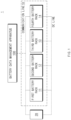
- the battery data management apparatus 100 may include a plurality of functional modules 110, a first broker 120, and a first controller 130.
- the plurality of functional modules 110 may include a first functional module 111, a second functional module 112, a third functional module 113, and a fourth functional module 114. Although the plurality of functional modules are illustrated as four in FIG. 2 , the present disclosure is not limited thereto, and the plurality of functional modules 110 may include n battery cells (n is a natural number equal to or greater than 2).
- Each of the plurality of functional modules 111, 112, 113, and 114 may perform a defined function based on a preset algorithm.
- each of the plurality of functional modules 111, 112, 113, and 114 may perform any one of battery data communication with the plurality of battery racks 11, 12, 13, and 14, control of the plurality of battery racks 11, 12, 13, and 14, and a user interface (UI) operation or battery data logging of the ESS 1 to which the battery data management apparatus 100 is applied. That is, the battery data management apparatus 100 may support load distribution by distinguishing functions of each of the plurality of function modules 111, 112, 113, and 114.
- each of the plurality of functional modules 111, 112, 113, and 114 may perform a defined function based on a control command of the first controller 130. That is, each of the plurality of functional modules 111, 112, 113, and 114 may perform a designated function based on a control command of the first controller 130.
- any one of the plurality of functional modules 111, 112, 113, and 114 may perform battery data communication with the plurality of battery racks 11, 12, 13, and 14 to obtain battery data.
- the first functional module 111 may perform wired and/or wireless communication with the first battery rack 11 that is any one of the plurality of battery racks 11, 12, 13, and 14.
- the first functional module 111 may communicate with the first battery rack 11 according to a differential input mode communication protocol.
- examples of the differential input mode communication protocol may include a controller area network (CAN), recommended standard 485 (RS-485), recommended standard 422 (RS-422), etc.
- the first functional module 111 may communicate with the first battery rack 11 according to a wireless communication protocol such as Wi-Fi (registered trademark), Bluetooth (registered trademark), etc.
- Each of the plurality of functional modules 111, 112, 113, and 114 may perform battery data communication with the first broker 120 to transmit the obtained battery data or the generated battery data. That is, the first broker 120 may obtain the battery data from the plurality of functional modules 111, 112, 113, and 114.
- the first broker 120 may relay linked operations among the plurality of functional modules 111, 112, 113, and 114 based on the battery data obtained from at least any one function module among the plurality of functional modules 111, 112, 113, and 114. More specifically, the first broker 120 may cache the battery data of the at least any one functional module among the plurality of functional modules 111, 112, 113, and 114. The first broker 120 may relay the plurality of functional modules 111, 112, 113, and 114 based on the battery data cached from the plurality of functional modules 111, 112, 113, and 114.
- the first broker 120 may transmit the battery data cached from the first functional module 111 to the second functional module 112 to relay the linked operations among the plurality of functional modules 111, 112, 113, and 114.
- the first broker 120 may transmit the battery data cached from the first functional module 111 where the failure occurs to the second functional module 112 that is drivable to relay operations among the plurality of functional modules 111, 112, 113, and 114.
- the first controller 130 may control operations of the plurality of functional modules 111, 112, 113, and 114 and the first broker 120.
- the first controller may control another drivable functional module to perform a designated function of the functional module. More specifically, when a failure occurs in at least any one functional module among the plurality of functional modules 111, 112, 113, and 114, the first controller may transmit a control command such that another drivable functional module performs the function.
- the battery data management apparatus 100 may drive each of the plurality of functional modules 111, 112, 113, and 114, the first broker 120 that manages the battery data of the plurality of functional modules 111, 112, 113, and 114, and the first controller 130 that controls the plurality of functional modules 111, 112, 113, and 114 and the first broker as a separate hardware device to perform a vertical scaling function. That is, to drive each of the plurality of functional modules 111, 112, 113, and 114, the first broker 120, and the first controller 130 of the battery data management apparatus 100 as a separate hardware device, application processing ability and storage capacity may be scaled up.
- the battery data management apparatus 100 may further include a second broker 140 and a second controller 150.
- the second broker 140 may relay linked operations among a plurality of functional modules 115, 116, 117, and 118 based on the battery data of at least any one function module among the plurality of functional modules 115, 116, 117, and 118. That is, the second broker 140 may horizontally scale up the function of the first broker 130 by performing the same function as the first broker 130.
- the battery data management apparatus 100 may process a load, which may be concentrated on any one of the first broker 130 or the second broker 140, in a distributed manner.
- the battery data management apparatus 100 may drive each of the plurality of functional modules 111, 112, 113, 114, 115, 116, 117, and 118, the first broker 120, the second broker 140, the first controller 130, and the second controller 150 as a separate hardware device to perform a vertical scaling function.
- a scale-out function may be performed in which functions processed in one hardware device are distributed into several hardware devices to improve a processing ability.
- the first broker 120 and the second broker 140 may share battery data cached from the plurality of functional modules 111, 112, 113, 114, 115, 116, 117, and 118.
- the first broker 120 may transmit the battery data cached from at least any one functional module among the plurality of functional modules 111, 112, 113, and 114 to the second broker 140 such that the second broker 140 controls linked operations of the plurality of functional modules 111, 112, 113, and 114.
- the second broker 140 may transmit the battery data cached from at least any one functional module among the plurality of functional modules 115, 116, 117, and 118 to the first broker 120 such that the first broker 120 controls linked operations of the plurality of functional modules 115, 116, 117, and 118.
- the second controller 150 may control operations of the plurality of functional modules 110 and the second broker 140.
- the second controller may control another drivable functional module to perform a designated function of the functional module. More specifically, when a failure occurs in at least any one functional module among the plurality of functional modules 111, 112, 113, and 114, the second controller may transmit a control command such that another drivable functional module performs the function.
- the second controller 150 may control at least any one function al module among the plurality of functional modules 111, 112, 113, and 114 performing battery data communication with the second broker 140 to perform battery data communication with the first broker 120. That is, the second controller 150 may perform change such that at least any one functional module among the plurality of functional modules 111, 112, 113, and 114 connected to the second broker 140 is connected to the first broker 120.
- the first controller 130 may control at least any one function al module among the plurality of functional modules 111, 112, 113, and 114 performing battery data communication with the first broker 120 to perform battery data communication with the second broker 140. That is, the first controller 130 may perform change such that at least any one functional module among the plurality of functional modules 111, 112, 113, and 114 connected to the first broker 120 is connected to the second broker 140.
- a battery data management apparatus 100 As described above, with a battery data management apparatus 100 according to an embodiment disclosed herein, it is possible to quickly process battery data at the same time and efficiently manage battery data, by distributing operations of functional modules.
- the battery data management apparatus 100 may perform a horizontal scaling function that drives a plurality of functional modules having relatively low performance without having mounted thereon a high-performance system, installation cost and resources required for maintenance may be reduced.
- the battery data management apparatus 100 may immediately respond to a failure in any one functional module or in the broker, thereby removing a down-time of the system.
- FIG. 4 is a flowchart of an operating method of a battery management apparatus according to an embodiment disclosed herein. Hereinbelow, an operating method of the battery data management apparatus 100 will be described with reference to FIGS. 1 to 3 .
- the battery data management apparatus 100 may be substantially the same as the battery data management apparatus 100 described with reference to FIGS. 1 to 3 , and thus will be briefly described to avoid redundant description.
- an operating method of the battery data management apparatus 100 may include operation S101 of performing, by the plurality of functional modules 110, a defined function based on a preset algorithm, operation S 102 of relaying, by the first broker 120, linked operations among the plurality of functional modules 110 based on battery data of at least any one functional module among the plurality of functional modules 110, operation S103 of relaying, by the second broker 140, linked operations among the plurality of functional modules 110 based on the battery data of the at least any one functional module among the plurality of functional modules 110, operation S104 of controlling, by the first controller 130, operations of the plurality of functional modules 110 and the first broker 120, and operation S105 of controlling, by the second controller 150, operations of the plurality of functional modules 110 and the second broker 140.
- each of the plurality of functional modules 111, 112, 113, and 114 may perform a defined function based on a preset algorithm.
- each of the plurality of functional modules 111, 112, 113, and 114 may perform any one of battery data communication with the plurality of battery racks 11, 12, 13, and 14, control of the plurality of battery racks 11, 12, 13, and 14, and a UI operation or battery data logging of the ESS 1 to which the battery data management apparatus 100 is applied. That is, the battery data management apparatus 100 may support load distribution by distinguishing functions of each of the plurality of function modules 111, 112, 113, and 114.
- each of the plurality of functional modules 111, 112, 113, and 114 may perform a defined function based on a control command of the first controller 130.
- the second broker 120 may relay linked operations among a plurality of functional modules 111, 112, 113, and 114 based on the battery data of at least any one function module among the plurality of functional modules 111, 112, 113, and 114.
- the first broker 120 may transmit the battery data cached from at least any one functional module among the plurality of functional modules 111, 112, 113, and 114 to the second broker 140 to perform synchronization with the second broker 140.
- the second broker 140 may relay linked operations among a plurality of functional modules 111, 112, 113, and 114 based on the battery data of at least any one function module among the plurality of functional modules 111, 112, 113, and 114.
- the second broker 140 may transmit the battery data cached from at least any one functional module among the plurality of functional modules 111, 112, 113, and 114 to the first broker 120 to perform synchronization with the first broker 120.
- the first controller 130 may control operations of the plurality of functional modules 111, 112, 113, and 114 and the first broker 120.
- the first controller 130 may control another drivable functional module to perform a designated function of the functional module.
- the first controller 130 may control at least any one function al module among the plurality of functional modules 111, 112, 113, and 114 performing battery data communication with the first broker 120 to perform battery data communication with the second broker 140.
- the second controller 150 may control operations of the plurality of functional modules 111, 112, 113, and 114 and the second broker 140.
- the second controller 150 may control another drivable functional module to perform a designated function of the functional module.
- the second controller 150 may control at least any one function al module among the plurality of functional modules 111, 112, 113, and 114 performing battery data communication with the second broker 140 to perform battery data communication with the first broker 120.
- FIG. 5 is a block diagram showing a hardware configuration of a computing system for performing an operating method of a battery data management apparatus, according to an embodiment disclosed herein.
- a computing system 200 may include an MCU 210, a memory 220, an input/output I/F 230, and a communication I/F 240.
- the MCU 210 may be a broker that executes various programs (e.g., a program for monitoring data of a battery, etc.) stored in the memory 220, processes various data through these programs, and performs the above-described functions of the battery data management apparatus 100 shown in FIG. 1 .
- programs e.g., a program for monitoring data of a battery, etc.
- the memory 220 may store various programs regarding operations of the battery data management apparatus 100. Moreover, the memory 220 may store operation data of the battery data management apparatus 100.
- the memory 220 may be provided in plural, depending on a need.
- the memory 220 may be volatile memory or non-volatile memory.
- RAM random access memory
- DRAM dynamic RAM
- SRAM static RAM
- ROM read only memory
- PROM programmable ROM
- EAROM electrically alterable ROM
- EPROM erasable PROM
- EEPROM electrically erasable PROM
- flash memory etc.
- the above-listed examples of the memory 220 are merely examples and are not limited thereto.
- the input/output I/F 230 may provide an interface for transmitting and receiving data by connecting an input device (not shown) such as a keyboard, a mouse, a touch panel, etc., and an output device such as a display (not shown), etc., to the MCU 210.
- an input device such as a keyboard, a mouse, a touch panel, etc.
- an output device such as a display (not shown), etc.
- the communication I/F 240 which is a component capable of transmitting and receiving various data to and from a server, may be various devices capable of supporting wired or wireless communication.
- a program for resistance measurement and abnormality diagnosis of the battery cell or various data may be transmitted and received to and from a separately provided external server through the communication I/F 240.
Landscapes
- Engineering & Computer Science (AREA)
- Business, Economics & Management (AREA)
- Power Engineering (AREA)
- Physics & Mathematics (AREA)
- General Physics & Mathematics (AREA)
- Tourism & Hospitality (AREA)
- Economics (AREA)
- Health & Medical Sciences (AREA)
- Primary Health Care (AREA)
- General Business, Economics & Management (AREA)
- Theoretical Computer Science (AREA)
- Strategic Management (AREA)
- Marketing (AREA)
- Human Resources & Organizations (AREA)
- General Health & Medical Sciences (AREA)
- Water Supply & Treatment (AREA)
- Public Health (AREA)
- Chemical & Material Sciences (AREA)
- Manufacturing & Machinery (AREA)
- Chemical Kinetics & Catalysis (AREA)
- Microelectronics & Electronic Packaging (AREA)
- General Chemical & Material Sciences (AREA)
- Electrochemistry (AREA)
- Charge And Discharge Circuits For Batteries Or The Like (AREA)
- Testing Electric Properties And Detecting Electric Faults (AREA)
Applications Claiming Priority (2)
| Application Number | Priority Date | Filing Date | Title |
|---|---|---|---|
| KR1020210148332A KR20230063264A (ko) | 2021-11-01 | 2021-11-01 | 배터리 데이터 관리 장치 및 그것의 동작 방법 |
| PCT/KR2022/016039 WO2023075292A1 (ko) | 2021-11-01 | 2022-10-20 | 배터리 데이터 관리 장치 및 그것의 동작 방법 |
Publications (3)
| Publication Number | Publication Date |
|---|---|
| EP4407549A1 true EP4407549A1 (de) | 2024-07-31 |
| EP4407549A4 EP4407549A4 (de) | 2025-01-29 |
| EP4407549B1 EP4407549B1 (de) | 2026-03-18 |
Family
ID=86159558
Family Applications (1)
| Application Number | Title | Priority Date | Filing Date |
|---|---|---|---|
| EP22887488.9A Active EP4407549B1 (de) | 2021-11-01 | 2022-10-20 | Batteriedatenverwaltungsvorrichtung und betriebsverfahren dafür |
Country Status (6)
| Country | Link |
|---|---|
| US (1) | US20240418781A1 (de) |
| EP (1) | EP4407549B1 (de) |
| JP (1) | JP7801035B2 (de) |
| KR (1) | KR20230063264A (de) |
| CN (1) | CN118140241A (de) |
| WO (1) | WO2023075292A1 (de) |
Family Cites Families (12)
| Publication number | Priority date | Publication date | Assignee | Title |
|---|---|---|---|---|
| US9564762B2 (en) * | 2010-11-02 | 2017-02-07 | Navitas Solutions | Fault tolerant wireless battery area network for a smart battery management system |
| JP6093448B2 (ja) * | 2013-11-01 | 2017-03-08 | 株式会社日立製作所 | 電池制御システム |
| KR102520912B1 (ko) * | 2015-12-29 | 2023-04-13 | 한국단자공업 주식회사 | 페일세이프 기능을 갖는 배터리 관리 시스템 및 방법 |
| KR102344211B1 (ko) * | 2017-12-20 | 2021-12-27 | 주식회사 엘지에너지솔루션 | 메인 제어부 이상 진단 시스템 및 방법 |
| US20190305386A1 (en) * | 2018-03-28 | 2019-10-03 | Navitas Solutions, Inc. | Fault-tolerant battery management |
| CN110896233B (zh) * | 2018-09-12 | 2021-07-30 | 宁德时代新能源科技股份有限公司 | 电池管理系统 |
| WO2020230572A1 (ja) | 2019-05-15 | 2020-11-19 | デンカ株式会社 | 膜担体及び検査キット |
| DE102020115333A1 (de) * | 2019-06-17 | 2020-12-17 | Silicon Works Co., Ltd. | Drahtloses Batterie-Verwaltungssystem, Knoten für drahtlose Kommunikation und Verfahren zur Datenübertragung |
| KR20200144053A (ko) * | 2019-06-17 | 2020-12-28 | 주식회사 실리콘웍스 | 무선 배터리 관리 시스템과 무선통신을 위한 노드 및 데이터 전송 방법 |
| CN112449333B (zh) * | 2019-08-30 | 2024-12-03 | 硅工厂股份有限公司 | 无线电池管理系统、用于无线通信的节点和网络建立方法 |
| KR102684713B1 (ko) * | 2020-03-11 | 2024-07-15 | 주식회사 엘지에너지솔루션 | 배터리 관리 시스템 및 이의 제어방법 |
| CN112428875A (zh) * | 2020-11-12 | 2021-03-02 | 重庆邮电大学 | 一种基于无线多智能体的电池管理系统 |
-
2021
- 2021-11-01 KR KR1020210148332A patent/KR20230063264A/ko active Pending
-
2022
- 2022-10-20 CN CN202280069624.1A patent/CN118140241A/zh active Pending
- 2022-10-20 EP EP22887488.9A patent/EP4407549B1/de active Active
- 2022-10-20 US US18/702,324 patent/US20240418781A1/en active Pending
- 2022-10-20 WO PCT/KR2022/016039 patent/WO2023075292A1/ko not_active Ceased
- 2022-10-20 JP JP2024525664A patent/JP7801035B2/ja active Active
Also Published As
| Publication number | Publication date |
|---|---|
| WO2023075292A1 (ko) | 2023-05-04 |
| US20240418781A1 (en) | 2024-12-19 |
| EP4407549B1 (de) | 2026-03-18 |
| CN118140241A (zh) | 2024-06-04 |
| JP7801035B2 (ja) | 2026-01-16 |
| EP4407549A4 (de) | 2025-01-29 |
| JP2024538302A (ja) | 2024-10-18 |
| KR20230063264A (ko) | 2023-05-09 |
Similar Documents
| Publication | Publication Date | Title |
|---|---|---|
| EP3011655B1 (de) | Verfahren zum steuern eines energiespeichersystems | |
| EP4102239A1 (de) | Batteriemanagementvorrichtung und -verfahren | |
| US20240410952A1 (en) | Battery management apparatus and operating method thereof | |
| EP4425198A1 (de) | Batteriekapazitätsvorhersagevorrichtung und betriebsverfahren dafür | |
| US20260110739A1 (en) | Battery State Management Apparatus and Operating Method Thereof | |
| KR102953708B1 (ko) | 배터리 관리 장치 및 그것의 동작 방법 | |
| EP4119960B1 (de) | Ladungs-/entladungsprüfsystem und verfahren zum steuern des ladungs-/entladungsprüfsystems | |
| EP4407549B1 (de) | Batteriedatenverwaltungsvorrichtung und betriebsverfahren dafür | |
| CN116806316A (zh) | 包括新安装电池架的能量存储系统和用于控制其的方法 | |
| EP4464545A1 (de) | Batterieverwaltungsvorrichtung und server | |
| EP4692824A1 (de) | Batterieverwaltungsvorrichtung und betriebsverfahren dafür | |
| EP4462139A1 (de) | Batterieverwaltungsvorrichtung und betriebsverfahren dafür | |
| EP4325232A1 (de) | Batterieverwaltungsvorrichtung und betriebsverfahren dafür | |
| EP4407829A1 (de) | Batterieverwaltungsvorrichtung und verfahren zum betrieb davon | |
| US11043840B2 (en) | Energy storage apparatus | |
| EP4365613B1 (de) | Batteriepack und betriebsverfahren dafür | |
| US20230163621A1 (en) | Battery management apparatus and method, and battery management system | |
| EP4589802A1 (de) | Batteriesystem, batterieverwaltungssystem und batterieverwaltungsverfahren | |
| EP4425199B1 (de) | Batteriedatenverwaltungsvorrichtung und betriebsverfahren | |
| EP4303599A1 (de) | Batterieselbstentladungsstrommessvorrichtung und betriebsverfahren dafür | |
| EP4307516A1 (de) | Batterieverwaltungsvorrichtung und -verfahren | |
| EP4306977B1 (de) | Vorrichtung zur vorhersage der batterielebensdauer und deren betriebsverfahren | |
| EP4647789A1 (de) | Batterieverwaltungsvorrichtung und server sowie batteriesystem damit | |
| EP4600678A1 (de) | Batterieverwaltungsvorrichtung und betriebsverfahren dafür | |
| EP4206708A1 (de) | Batterieverwaltungsvorrichtung und -verfahren |
Legal Events
| Date | Code | Title | Description |
|---|---|---|---|
| STAA | Information on the status of an ep patent application or granted ep patent |
Free format text: STATUS: THE INTERNATIONAL PUBLICATION HAS BEEN MADE |
|
| PUAI | Public reference made under article 153(3) epc to a published international application that has entered the european phase |
Free format text: ORIGINAL CODE: 0009012 |
|
| STAA | Information on the status of an ep patent application or granted ep patent |
Free format text: STATUS: REQUEST FOR EXAMINATION WAS MADE |
|
| 17P | Request for examination filed |
Effective date: 20240423 |
|
| AK | Designated contracting states |
Kind code of ref document: A1 Designated state(s): AL AT BE BG CH CY CZ DE DK EE ES FI FR GB GR HR HU IE IS IT LI LT LU LV MC ME MK MT NL NO PL PT RO RS SE SI SK SM TR |
|
| A4 | Supplementary search report drawn up and despatched |
Effective date: 20250108 |
|
| RIC1 | Information provided on ipc code assigned before grant |
Ipc: H02J 7/00 20060101ALI20241223BHEP Ipc: G06F 119/06 20200101ALI20241223BHEP Ipc: G06Q 50/10 20120101ALI20241223BHEP Ipc: G06Q 50/06 20240101AFI20241223BHEP |
|
| DAV | Request for validation of the european patent (deleted) | ||
| DAX | Request for extension of the european patent (deleted) | ||
| GRAP | Despatch of communication of intention to grant a patent |
Free format text: ORIGINAL CODE: EPIDOSNIGR1 |
|
| STAA | Information on the status of an ep patent application or granted ep patent |
Free format text: STATUS: GRANT OF PATENT IS INTENDED |
|
| INTG | Intention to grant announced |
Effective date: 20251017 |
|
| P01 | Opt-out of the competence of the unified patent court (upc) registered |
Free format text: CASE NUMBER: UPC_APP_0012213_4407549/2025 Effective date: 20251105 |
|
| GRAS | Grant fee paid |
Free format text: ORIGINAL CODE: EPIDOSNIGR3 |
|
| GRAA | (expected) grant |
Free format text: ORIGINAL CODE: 0009210 |
|
| STAA | Information on the status of an ep patent application or granted ep patent |
Free format text: STATUS: THE PATENT HAS BEEN GRANTED |
|
| AK | Designated contracting states |
Kind code of ref document: B1 Designated state(s): AL AT BE BG CH CY CZ DE DK EE ES FI FR GB GR HR HU IE IS IT LI LT LU LV MC ME MK MT NL NO PL PT RO RS SE SI SK SM TR |
|
| REG | Reference to a national code |
Ref country code: CH Ref legal event code: F10 Free format text: ST27 STATUS EVENT CODE: U-0-0-F10-F00 (AS PROVIDED BY THE NATIONAL OFFICE) Effective date: 20260318 Ref country code: GB Ref legal event code: FG4D |
|
| REG | Reference to a national code |
Ref country code: IE Ref legal event code: FG4D |
|
| REG | Reference to a national code |
Ref country code: DE Ref legal event code: R096 Ref document number: 602022032747 Country of ref document: DE |