EP4407564A1 - Laparoskopisches bildmanipulationsverfahren und -system - Google Patents
Laparoskopisches bildmanipulationsverfahren und -system Download PDFInfo
- Publication number
- EP4407564A1 EP4407564A1 EP23193505.7A EP23193505A EP4407564A1 EP 4407564 A1 EP4407564 A1 EP 4407564A1 EP 23193505 A EP23193505 A EP 23193505A EP 4407564 A1 EP4407564 A1 EP 4407564A1
- Authority
- EP
- European Patent Office
- Prior art keywords
- model
- laparoscopic
- images
- computer
- visual representation
- Prior art date
- Legal status (The legal status is an assumption and is not a legal conclusion. Google has not performed a legal analysis and makes no representation as to the accuracy of the status listed.)
- Pending
Links
Images


Classifications
-
- G—PHYSICS
- G06—COMPUTING OR CALCULATING; COUNTING
- G06T—IMAGE DATA PROCESSING OR GENERATION, IN GENERAL
- G06T19/00—Manipulating three-dimensional [3D] models or images for computer graphics
- G06T19/006—Mixed reality
-
- G—PHYSICS
- G06—COMPUTING OR CALCULATING; COUNTING
- G06T—IMAGE DATA PROCESSING OR GENERATION, IN GENERAL
- G06T19/00—Manipulating three-dimensional [3D] models or images for computer graphics
- G06T19/20—Editing of three-dimensional [3D] images, e.g. changing shapes or colours, aligning objects or positioning parts
-
- G—PHYSICS
- G06—COMPUTING OR CALCULATING; COUNTING
- G06T—IMAGE DATA PROCESSING OR GENERATION, IN GENERAL
- G06T2210/00—Indexing scheme for image generation or computer graphics
- G06T2210/41—Medical
-
- G—PHYSICS
- G06—COMPUTING OR CALCULATING; COUNTING
- G06T—IMAGE DATA PROCESSING OR GENERATION, IN GENERAL
- G06T2219/00—Indexing scheme for manipulating 3D models or images for computer graphics
- G06T2219/20—Indexing scheme for editing of 3D models
- G06T2219/2012—Colour editing, changing, or manipulating; Use of colour codes
Definitions
- the present disclosure relates to a method and a system for manipulating laparoscopic images taken during a laparoscopic procedure using a video laparoscope as well as to a non-volatile data storage medium containing instructions for a computer.
- the operator views an image produced by the video laparoscope on a screen, which may be the primary OP monitor.
- the laparoscopic image presented to the operator is enhanced by overlaying the laparoscopic image with a rendering of a 3D model of an organ being operated on or other organic structures.
- 3D models serve for orientation and navigation during the procedure and are generated beforehand based on prior radiological scans of the patient.
- Such an overlay of a 3D model will cover parts of the life surgical image, depending on its position and orientation. In case of excessive similarity between the structures shown in the two parts of the composite image, the overlay may be difficult to distinguish from the actual laparoscopic image.
- the overlaid 3D model of the organ blends visually with the laparoscopic image. This may lead to loss of detail or, in extreme cases to confusion between the live surgical image in the background and the overlay display in certain details.
- Another artifact of the overlay is that the overlaid image of the 3D model of the organ may obstruct the view of surgical instruments inside the laparoscopic image.
- Such object can be solved by a method for manipulating laparoscopic images taken during a laparoscopic procedure using a video laparoscope by
- the composite images may be displayed on a screen.
- the laparoscopic images are manipulated in real-time.
- the object of which a 3D model is used may be at least one of one or several organs and an organic structure.
- the 3D model of the object is not only rendered as an overlay over the laparoscopic images, but adjusted to have greater contrast to the underlying images, thus fulfilling the goals of better assisting the operator by reducing the risk of confusion between the 3D model visualization and the real laparoscopic images. This is done by identifying regions of insufficient color or brightness contrast and adjusting the visualization of the 3D model in those regions, in particular by increasing the contrast with regard to color and/or brightness.
- At least one of the comparison and the adjustment of the visual representation of the 3D model is done at least one of at pixel level of the laparoscopic images and in segments of multiple pixels. Whereas a pixel level comparison and/or adjustment will result in most detailed composite images, the use of segments of multiple pixels will take less computational time and may be used, among others, for increasing the repetition rate of the enhanced laparoscopic images.
- the segmentation in the comparison may differ from the segmentation in the adjustment of the visual representation of the 3D model.
- the segments in the adjustment of the visual representation of the 3D model may be circular or elliptical and fully encompass the segments used in the comparison. This latter feature serves to make the rendering of the 3D model more natural and avoid any rastering effects.
- the brightness of the laparoscopic images may be reduced and/or the brightness of the visual representation of the 3D model may be increased. Both measures further increase the contrast between the visualization of the 3D model and the laparoscopic images.
- a further embodiment includes detecting a surgical instrument in the laparoscopic images and adjusting the visual representation of the 3D model to avoid obscuring the surgical instrument. This may be done by making the 3D model visualization more transparent in the region of the laparoscopic image containing the surgical instrument or by cutting out the part of the organ that would be obscured by the surgical instrument from the rendering of the 3D model of the object. This would make the surgical instrument appear to be in front of the 3D model of the object in perspective.
- the detection of the surgical instrument may be performed by at least one of object recognition and edge detection, for example.
- details from the inner region of the 3D model of the object may be left out, only the outer contours of the 3D model may be rendered or pre-determined edges of the 3D model including the outer contours of the 3D model may be rendered.
- the outer contours of the 3D model may be outlined in two highly contrasting colors or brightnesses. By this means, the outlines will be visible equally against bright, dark and midtone backgrounds. In color images, the contrasting colors may be chosen to represent complementary colors, in particular colors having the greatest contrast to the predominant colors of the laparoscopic images.
- a further aspect of the present invention resides in a system for manipulating laparoscopic images taken during a laparoscopic procedure using a video laparoscope comprising a video laparoscope, a camera controller configured for controlling the video laparoscope, a computer having a frame grabber configured to capture laparoscopic images from the video laparoscope, and a screen connected to the computer, the computer (14) being configured to
- the system thereby embodies the same features, characteristics and solutions as the afore-described method.
- the computer is configured to perform at least one of the comparison and the adjustment of the visual representation of the 3D model at least one of at pixel level of the laparoscopic images and in segments of multiple pixels.
- the computer is configured to at least one of reduce the brightness of the laparoscopic images and increase the brightness of the visual representation of the 3D model.
- the computer is configured to detect a surgical instrument in the laparoscopic images and adjust the visual representation of the 3D model to avoid obscuring the surgical instrument.
- the computer is configured to perform the detection of the surgical instrument by at least one of object recognition and edge detection.
- the computer may be configured to leave out details from the inner region of the 3D model of the object.
- the computer is configured to render at least one of the outer contours of the 3D model and pre-determined edges of the 3D model including the outer contours of the 3D model.
- the computer is configured to outline the outer contours of the 3D model in two highly contrasting colors or brightnesses.
- Another aspect of the present invention resides in a non-volatile data storage medium containing instructions for a computer that are configured for causing the computer to perform the above-described method. Such instructions may be loaded in a computer or its frame grabber of an above-described system.
- Embodiments can fulfill individual features or a combination of several features.
- a composite image 6 of a laparoscopic procedure produced according to known methods as could be shown on the central operating monitor of an operating room.
- a 3D model 4 of an organic structure is rendered and overlayed over a live laparoscopic image 2, thereby highlighting important organic structures in the operating field.
- the 3D model has, for example, been generated based on prior radiological scans of the patient.
- the region having numeral "1" includes a part of the background laparoscopic image 2 that has very similar color and/or brightness values as the rendering of the 3D model 4 of the organic structure, thereby rendering it difficult to distinguish between the 3D model and the real laparoscopic image.
- the other region having the numeral "2" shows that the rendering of the 3D model 4 obscures the view of a surgical instrument 8 that is presently used to manipulate organic structures in the operating area. Both kinds of artefacts may irritate the surgeon.
- Fig. 2 illustrates a composite image 6 of a laparoscopic procedure produced according to a first embodiment.
- a composite image 6 of a laparoscopic image 2 and overlaid 3D model 4 of organs and other organic structures is shown.
- 3D model 4 different organic structures are represented with different colors for enhanced distinction among each other.
- the rendering of the 3D model 4 is based on radiological data of the organs and organic structures that were obtained in radiological scans prior to the laparoscopic procedure.
- the rendering of the 3D model 4 has been generated according to the inventive method, wherein the rendering of the 3D model 4 was compared to the laparoscopic image 2 on a pixel basis and its distance in color and/or brightness adjusted for clearer distinctiveness in regions where the difference in color and/or brightness was too small originally. Due to this enhancement, the surgeon has a clear picture of which part of the composite image 6 represent the life laparoscopic image 2 and which parts represent the 3D model 4.
- Fig. 3 illustrates a schematic representation of an embodiment of a system 10 for manipulating laparoscopic images 2.
- the system 10 comprises the source of laparoscopic images 2, namely a video laparoscope 11, which is connected to a camera controller 12 that is designed and configured to control the operation of video laparoscope 11 and receive image data of the laparoscopic images 2 from the video laparoscope 11.
- the camera controller 12 is also connected to a computer 14 having the frame grabber 16, which may be embodied in software or as a hardware card connected to or inserted in computer 14.
- Frame grabber 16 is designed and configured to process the individual frames of laparoscopic images 2.
- the manipulation of the individual frames of laparoscopic images 2 may be done inside the frame grabber 16, or computer 14, as the case may be.
- Computer 14, or frame grabber 16, as the case may be, has in its memory a 3D model 4 of organs or organic structures of the patient who is being examined with the video laparoscope 11 and configured to match the location and orientation of the 3D model 4 with the life surgical laparoscopic images 2.
- software running on computer 14 or frame grabber 16, as the case may be combines the laparoscopic images 2 with a rendering of the 3D model 4 to form a composite image 6 which then is displayed on a screen 18.
- Fig. 4 illustrates a composite image 6 of a laparoscopic procedure produced according to a second embodiment of the method according to the invention.
- a surgical instrument 8 has been detected in the laparoscopic image 2.
- the immediate vicinity of the surgical instrument 8 is defined as a cutout region 20 and removed from the rendering of the 3D model 4, thus clearing the view of surgical instrument 8 and its vicinity.
- the remainder of the rendering of 3D models 4 provides the surgeon with visual information regarding orientation and location of the operating area displayed in laparoscopic image 2.
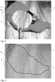
- Fig. 5 illustrates a composite image of a laparoscopic procedure produced according to a third embodiment.
- the 3D model 4 of the organic structure overlays over the real time laparoscopic image 2 solely as an outline, in this case a high contrast contour 22.
- the high contrast contour 22 has the form of a double line of different colors, the two lines being immediately adjacent to one another.
- one of the lines is white and the other black, since white and black provide the starkest possible contrast in brightness.
- Such a high contrast contour 22 will be visible over any background structures, since in regions with low brightness, the white line will stand out whereas in regions with high brightness, the black line will stand out.
- colored lines having a high color contrast may be used.
- the colors may also be chosen to have the best possible color contrast to the red color background of typical laparoscopic images 2.
- the high contrast contour 22 of the third embodiment shown in Fig. 5 may be an alternative representation of the 3D model 4 to those shown in Figs. 2 and 4 .
- Figs. 2 , 4 and 5 also show further differences and variations that can be used to enhance the contrast between the representation of the 3D model 4 and the background laparoscopic image 2, such as increasing the brightness of the rendering of the 3D model 4, decreasing the brightness of the background laparoscopic image 2 or increasing contrast and/or color contrast in one of the two images, such as the rendering of 3D model 4.
- Fig. 6 illustrates a schematic diagram of an exemplary schematic representation of a machine learning model 30 setup that is configured to recognize objects, such as organs, organic structures or surgical tools in the laparoscopic images 2 supplied as input features by video laparoscope 11.
- the machine learning model 30 includes an input interface 32 through which 3D model data which are specific to a patient are provided as input features to an artificial intelligence (Al) model 34, a processor which performs an inference operation in which the laparoscopic images 2 and the 3D model data are applied to the Al model 34 to generate a location and orientation of the organs or organic structures represented in the 3D model, and possibly of surgical instruments that may be visible in the laparoscopic images 2.
- Al artificial intelligence
- a composite image 6 of the laparoscopic images 2 overlaid with a rendering of the 3D model 4, which may be refined upon detecting a surgical instrument 8 in the laparoscopic images 2, can be generated and shown to a user, e.g., a clinician, on a screen 18.
- the input interface 32 may be a direct data link between the machine learning model 30 and one or more medical devices that generate at least some of the input features.
- the input interface 32 may transmit laparoscopic images 2 directly to the machine learning model 30 during a therapeutic and/or diagnostic medical procedure.
- the input interface 32 may be a classical user interface that facilitates interaction between a user and the machine learning model 30.
- the input interface 32 may facilitate a user interface through which the user may manually enter laparoscopic images 2.
- the input interface 32 may provide a machine learning model 30 with access to an electronic patient record from which one or more laparoscopic images or 3D model data may be extracted as input features.
- the input interface 32 is configured to collect one or more of the input features in association with a specific patient on or before a time at which the machine learning model 30 is used to assess the presence, location and orientation of organs, organic structures and/or surgical instruments.
- the processor performs an inference operation using the AI model to generate the above-described system output.
- input interface 32 may deliver the laparoscopic features into an input layer of the AI model 34 which propagates these input features through the AI model 34 to an output layer.
- the AI model 34 can provide the system 10 the ability to perform tasks, without explicitly being programmed, by making inferences based on patterns found in the analysis of data.
- AI model 34 explores the study and construction of algorithms (e.g., machine-learning algorithms) that may learn from existing data and make predictions about new data. Such algorithms operate by building an AI model 34 from example training data in order to make data-driven predictions or decisions expressed as outputs or assessments.
- ML machine learning
- Supervised ML uses prior knowledge (e.g., examples that correlate inputs to outputs or outcomes) to learn the relationships between the inputs and the outputs.
- the goal of supervised ML is to learn a function that, given some training data, best approximates the relationship between the training inputs and outputs so that the ML model can implement the same relationships when given inputs to generate the corresponding outputs.
- Unsupervised ML is the training of an ML algorithm using information that is neither classified nor labeled, and allowing the algorithm to act on that information without guidance. Unsupervised ML is useful in exploratory analysis because it can automatically identify structure in data.
- Classification problems also referred to as categorization problems, aim at classifying items into one of several category values (for example, is this object an apple or an orange?).
- Regression algorithms aim at quantifying some items (for example, by providing a score to the value of some input).
- Some examples of commonly used supervised-ML algorithms are Logistic Regression (LR), Naive-Bayes, Random Forest (RF), neural networks (NN), deep neural networks (DNN), matrix factorization, and Support Vector Machines (SVM).
- Some common tasks for unsupervised ML include clustering, representation learning, and density estimation.
- Some examples of commonly used unsupervised-ML algorithms are K-means clustering, principal component analysis, and autoencoders.
- federated learning also known as collaborative learning
- This approach stands in contrast to traditional centralized machine-learning techniques where all the local datasets are uploaded to one server, as well as to more classical decentralized approaches which often assume that local data samples are identically distributed.
- Federated learning enables multiple actors to build a common, robust machine learning model without sharing data, thus allowing to address critical issues such as data privacy, data security, data access rights and access to heterogeneous data.
- the AI model may be trained continuously or periodically prior to performance of the inference operation by the processor running the AI model 34. Then, during the inference operation, the patient specific input features provided to the AI model 34 may be propagated from an input layer, through one or more hidden layers, and ultimately to an output layer that corresponds to the location, orientation and type of structure found in the laparoscopic images. For example, the AI model 34 may identify the type, location and orientation of specific organs or organic structures represented in the patient specific 3D model, or the location and, if applicable, type and/or orientation, of a surgical instrument, in the laparoscopic images 2.
- the thus found locations, types and/or orientations of objects may be communicated to the user via a user interface (Ul), in particular by rendering the correspondingly positioned and oriented 3D model 4.
- the AI model 34 may also have as an output information that aids to define a cutout region 20 in the rendering of the 3D model 4 for composite images 6 in the presence of a surgical tool 8.
Landscapes
- Engineering & Computer Science (AREA)
- Computer Graphics (AREA)
- Computer Hardware Design (AREA)
- General Engineering & Computer Science (AREA)
- Software Systems (AREA)
- Physics & Mathematics (AREA)
- General Physics & Mathematics (AREA)
- Theoretical Computer Science (AREA)
- Architecture (AREA)
- Endoscopes (AREA)
- Image Analysis (AREA)
- Medical Treatment And Welfare Office Work (AREA)
Applications Claiming Priority (1)
| Application Number | Priority Date | Filing Date | Title |
|---|---|---|---|
| US202363440939P | 2023-01-25 | 2023-01-25 |
Publications (1)
| Publication Number | Publication Date |
|---|---|
| EP4407564A1 true EP4407564A1 (de) | 2024-07-31 |
Family
ID=87845873
Family Applications (1)
| Application Number | Title | Priority Date | Filing Date |
|---|---|---|---|
| EP23193505.7A Pending EP4407564A1 (de) | 2023-01-25 | 2023-08-25 | Laparoskopisches bildmanipulationsverfahren und -system |
Country Status (4)
| Country | Link |
|---|---|
| US (1) | US20240249487A1 (de) |
| EP (1) | EP4407564A1 (de) |
| JP (1) | JP2024105192A (de) |
| DE (1) | DE102024102047B3 (de) |
Cited By (1)
| Publication number | Priority date | Publication date | Assignee | Title |
|---|---|---|---|---|
| CN118972543A (zh) * | 2024-10-18 | 2024-11-15 | 杭州川核灵境科技有限公司 | 一种3d立体追踪的实时显示调节方法及系统 |
Families Citing this family (1)
| Publication number | Priority date | Publication date | Assignee | Title |
|---|---|---|---|---|
| CN119132523A (zh) * | 2024-09-25 | 2024-12-13 | 中国人民解放军海军军医大学第三附属医院 | 腹腔镜辅助标识的确定方法 |
Family Cites Families (16)
| Publication number | Priority date | Publication date | Assignee | Title |
|---|---|---|---|---|
| US7184063B2 (en) * | 2004-09-01 | 2007-02-27 | Microsoft Corporation | Adaptive color schemes |
| US20090096807A1 (en) * | 2007-08-27 | 2009-04-16 | Silverstein Jonathan C | Systems and methods for image colorization |
| WO2014160510A2 (en) * | 2013-03-13 | 2014-10-02 | Massachusetts Institute Of Technology | Photometric stereo endoscopy |
| EP3117405B1 (de) * | 2014-03-10 | 2025-11-19 | Smith&Nephew, Inc. | Systeme und verfahren zur beurteilung der genauigkeit eines patientenmodells |
| JP6323183B2 (ja) * | 2014-06-04 | 2018-05-16 | ソニー株式会社 | 画像処理装置および画像処理方法 |
| US10643371B2 (en) * | 2014-08-11 | 2020-05-05 | Covidien Lp | Treatment procedure planning system and method |
| US10495884B2 (en) * | 2014-12-14 | 2019-12-03 | Elbit Systems Ltd. | Visual perception enhancement of displayed color symbology |
| US10154239B2 (en) | 2014-12-30 | 2018-12-11 | Onpoint Medical, Inc. | Image-guided surgery with surface reconstruction and augmented reality visualization |
| CN107667380A (zh) * | 2015-06-05 | 2018-02-06 | 西门子公司 | 用于内窥镜和腹腔镜导航的同时场景解析和模型融合的方法和系统 |
| JP6112689B1 (ja) * | 2016-02-17 | 2017-04-12 | 株式会社菊池製作所 | 重畳画像表示システム |
| US10460457B2 (en) | 2016-07-12 | 2019-10-29 | Novartis Ag | Adaptive adjustment of overlay image parameters |
| US10010379B1 (en) * | 2017-02-21 | 2018-07-03 | Novarad Corporation | Augmented reality viewing and tagging for medical procedures |
| WO2019047985A1 (zh) * | 2017-09-11 | 2019-03-14 | Oppo广东移动通信有限公司 | 图像处理方法和装置、电子装置和计算机可读存储介质 |
| JP2019161558A (ja) * | 2018-03-15 | 2019-09-19 | 国立大学法人 東京大学 | 臓器追跡装置、臓器追跡方法及び臓器追跡プログラム |
| EP3983844A1 (de) * | 2019-06-14 | 2022-04-20 | Leica Instruments (Singapore) Pte Ltd | Optische anordnung, beobachtungsgerät und verfahren zur optischen überlagerung von eingangsbildern |
| EP4430564A4 (de) * | 2021-11-09 | 2025-09-24 | Genesis Medtech Usa Inc | Interaktives system für erweiterte realität für laparoskopische und videounterstützte chirurgie |
-
2023
- 2023-08-25 EP EP23193505.7A patent/EP4407564A1/de active Pending
- 2023-11-08 US US18/387,930 patent/US20240249487A1/en active Pending
-
2024
- 2024-01-12 JP JP2024003443A patent/JP2024105192A/ja active Pending
- 2024-01-24 DE DE102024102047.4A patent/DE102024102047B3/de active Active
Non-Patent Citations (6)
| Title |
|---|
| BERTRAND LE ROY ET AL: "A case series study of augmented reality in laparoscopic liver resection with a deformable preoperative model", SURGICAL ENDOSCOPY, SPRINGER US, NEW YORK, vol. 34, no. 12, 20 July 2020 (2020-07-20), pages 5642 - 5648, XP037286431, ISSN: 0930-2794, [retrieved on 20200720], DOI: 10.1007/S00464-020-07815-X * |
| CHRISTIAN HEILIGER: "Phantom study on surgical performance in augmented reality laparoscopy", INTERNATIONAL JOURNAL OF COMPUTER ASSISTED RADIOLOGY AND SURGERY; A JOURNAL FOR INTERDISCIPLINARY RESEARCH, DEVELOPMENT AND APPLICATIONS OF IMAGE GUIDED DIAGNOSIS AND THERAPY, vol. 18, no. 8, 22 December 2022 (2022-12-22), Berlin, DE, pages 1345 - 1354, XP093152685, ISSN: 1861-6429, Retrieved from the Internet <URL:https://link.springer.com/content/pdf/10.1007/s11548-022-02809-7.pdf> DOI: 10.1007/s11548-022-02809-7 * |
| DU CHENGXU ET AL: "Intraoperative navigation system with a multi-modality fusion of 3D virtual model and laparoscopic real-time images in laparoscopic pancreatic surgery: a preclinical study", BMC SURGERY, vol. 22, no. 1, 1 December 2022 (2022-12-01), GB, XP093129694, ISSN: 1471-2482, Retrieved from the Internet <URL:https://bmcsurg.biomedcentral.com/counter/pdf/10.1186/s12893-022-01585-0.pdf> DOI: 10.1186/s12893-022-01585-0 * |
| ICHIHASHI KEITA ET AL: "Estimating Visibility of Annotations for View Management in Spatial Augmented Reality Based on Machine-Learning Techniques", SENSORS, vol. 19, no. 4, 22 February 2019 (2019-02-22), CH, pages 939, XP093129679, ISSN: 1424-8220, Retrieved from the Internet <URL:https://www.ncbi.nlm.nih.gov/pmc/articles/PMC6412218/pdf/sensors-19-00939.pdf> DOI: 10.3390/s19040939 * |
| RAWIA FRIKHA: "Handling occlusion in Augmented Reality surgical training based instrument tracking", 2016 IEEE/ACS 13TH INTERNATIONAL CONFERENCE OF COMPUTER SYSTEMS AND APPLICATIONS (AICCSA), 1 November 2016 (2016-11-01), pages 1 - 5, XP093152682, ISBN: 978-1-5090-4320-0, Retrieved from the Internet <URL:https://ieeexplore.ieee.org/stampPDF/getPDF.jsp?tp=&arnumber=7945729&ref=aHR0cHM6Ly9pZWVleHBsb3JlLmllZWUub3JnL2RvY3VtZW50Lzc5NDU3Mjk=> DOI: 10.1109/AICCSA.2016.7945729 * |
| SOLER LUC ET AL: "Real-time 3D image reconstruction guidance in liver resection surgery", HAL (LE CENTRE POUR LA COMMUNICATION SCIENTIFIQUE DIRECTE), 1 April 2014 (2014-04-01), China (Republic : 1949- ), pages 73 - 81, XP093129697, Retrieved from the Internet <URL:https://cdn.amegroups.cn/journals/amepc/files/journals/14/articles/3634/public/3634-PB3-R2.pdf> [retrieved on 20240209], DOI: 10.3978/j.issn.2304-3881.2014.02.03 * |
Cited By (1)
| Publication number | Priority date | Publication date | Assignee | Title |
|---|---|---|---|---|
| CN118972543A (zh) * | 2024-10-18 | 2024-11-15 | 杭州川核灵境科技有限公司 | 一种3d立体追踪的实时显示调节方法及系统 |
Also Published As
| Publication number | Publication date |
|---|---|
| DE102024102047B3 (de) | 2024-05-16 |
| US20240249487A1 (en) | 2024-07-25 |
| JP2024105192A (ja) | 2024-08-06 |
Similar Documents
| Publication | Publication Date | Title |
|---|---|---|
| US9805469B2 (en) | Marking and tracking an area of interest during endoscopy | |
| US20240249487A1 (en) | Laparoscopic image manipulation method and system | |
| JP6799301B2 (ja) | 情報処理装置、制御方法、及びプログラム | |
| US20210327563A1 (en) | Salient visual explanations of feature assessments by machine learning models | |
| US20150080652A1 (en) | Lesion detection and image stabilization using portion of field of view | |
| JP6716853B2 (ja) | 情報処理装置、制御方法、及びプログラム | |
| US20250248585A1 (en) | Information processing apparatus, control method, and program | |
| US12131818B2 (en) | Systems and methods for providing surgical guidance | |
| US11896323B2 (en) | System, method, and computer-accessible medium for automatically tracking and/or identifying at least one portion of an anatomical structure during a medical procedure | |
| US20230137862A1 (en) | System, Method, and Computer Program for a Microscope of a Surgical Microscope System | |
| Feng et al. | ST-ITEF: Spatio-Temporal Intraoperative Task Estimating Framework to recognize surgical phase and predict instrument path based on multi-object tracking in keratoplasty | |
| JP2022132180A (ja) | 人工知能基盤の胃内視鏡映像診断支援システム及び方法 | |
| US12511739B2 (en) | Computer aided assistance system and method | |
| WO2020038771A1 (en) | Salient visual relevancy of feature assessments by machine learning models | |
| JP2013017660A (ja) | 舌診支援プログラム、舌診支援装置 | |
| US20240153075A1 (en) | Electronic device for ai-based recommendation of melanoma biopsy site and method for performing the same | |
| EP4579584A1 (de) | Verfahren und system zur automatischen erkennung und markierung von dünnkappenfibroatheromen in einem oct-bild | |
| US20220277451A1 (en) | Systems, methods and apparatuses for visualization of imaging data | |
| Sharma | Medical image processing using AI | |
| EP4413911A1 (de) | Verfahren und system zur verarbeitung von fluoreszenzbildgeführten chirurgischen oder diagnostischen bildern | |
| US20260024209A1 (en) | Method of analyzing 3d data acquired by a 3d image-producing procedure in an area of inspection, computer-based clinical decision support system, computer program product and computer-readable medium | |
| Gaurkhede et al. | A Review on Automated Facial Expression Recognition Using Image Emotion Analysis | |
| Aguilar et al. | Advances in the use of neurophysiologycally-based fusion for visualization and pattern recognition of medical imagery | |
| Rahbar | Visual Intelligence for Robotic and Laparoscopic Surgery: A Real-Time System for Bleeding Detection and Prediction | |
| KR20250024457A (ko) | 의료영상에서 조작된 부위를 판별하기 위한 의료영상 분석장치 및 방법 |
Legal Events
| Date | Code | Title | Description |
|---|---|---|---|
| PUAI | Public reference made under article 153(3) epc to a published international application that has entered the european phase |
Free format text: ORIGINAL CODE: 0009012 |
|
| STAA | Information on the status of an ep patent application or granted ep patent |
Free format text: STATUS: THE APPLICATION HAS BEEN PUBLISHED |
|
| AK | Designated contracting states |
Kind code of ref document: A1 Designated state(s): AL AT BE BG CH CY CZ DE DK EE ES FI FR GB GR HR HU IE IS IT LI LT LU LV MC ME MK MT NL NO PL PT RO RS SE SI SK SM TR |
|
| STAA | Information on the status of an ep patent application or granted ep patent |
Free format text: STATUS: REQUEST FOR EXAMINATION WAS MADE |
|
| 17P | Request for examination filed |
Effective date: 20241030 |
|
| RBV | Designated contracting states (corrected) |
Designated state(s): AL AT BE BG CH CY CZ DE DK EE ES FI FR GB GR HR HU IE IS IT LI LT LU LV MC ME MK MT NL NO PL PT RO RS SE SI SK SM TR |
|
| STAA | Information on the status of an ep patent application or granted ep patent |
Free format text: STATUS: EXAMINATION IS IN PROGRESS |
|
| 17Q | First examination report despatched |
Effective date: 20260327 |