EP4407675A1 - Verstellbarer wärmeverteiler für einen kühlkörper - Google Patents
Verstellbarer wärmeverteiler für einen kühlkörper Download PDFInfo
- Publication number
- EP4407675A1 EP4407675A1 EP23153311.8A EP23153311A EP4407675A1 EP 4407675 A1 EP4407675 A1 EP 4407675A1 EP 23153311 A EP23153311 A EP 23153311A EP 4407675 A1 EP4407675 A1 EP 4407675A1
- Authority
- EP
- European Patent Office
- Prior art keywords
- insert
- heat sink
- adjustable
- heat
- cooled
- Prior art date
- Legal status (The legal status is an assumption and is not a legal conclusion. Google has not performed a legal analysis and makes no representation as to the accuracy of the status listed.)
- Granted
Links
Images

Classifications
-
- F—MECHANICAL ENGINEERING; LIGHTING; HEATING; WEAPONS; BLASTING
- F28—HEAT EXCHANGE IN GENERAL
- F28F—DETAILS OF HEAT-EXCHANGE AND HEAT-TRANSFER APPARATUS, OF GENERAL APPLICATION
- F28F3/00—Plate-like or laminated elements; Assemblies of plate-like or laminated elements
- F28F3/02—Elements or assemblies thereof with means for increasing heat-transfer area, e.g. with fins, with recesses, with corrugations
- F28F3/06—Elements or assemblies thereof with means for increasing heat-transfer area, e.g. with fins, with recesses, with corrugations the means being attachable to the element
-
- H—ELECTRICITY
- H05—ELECTRIC TECHNIQUES NOT OTHERWISE PROVIDED FOR
- H05K—PRINTED CIRCUITS; CASINGS OR CONSTRUCTIONAL DETAILS OF ELECTRIC APPARATUS; MANUFACTURE OF ASSEMBLAGES OF ELECTRICAL COMPONENTS
- H05K7/00—Constructional details common to different types of electric apparatus
- H05K7/20—Modifications to facilitate cooling, ventilating, or heating
- H05K7/20845—Modifications to facilitate cooling, ventilating, or heating for automotive electronic casings
- H05K7/20872—Liquid coolant without phase change
-
- H—ELECTRICITY
- H10—SEMICONDUCTOR DEVICES; ELECTRIC SOLID-STATE DEVICES NOT OTHERWISE PROVIDED FOR
- H10W—GENERIC PACKAGES, INTERCONNECTIONS, CONNECTORS OR OTHER CONSTRUCTIONAL DETAILS OF DEVICES COVERED BY CLASS H10
- H10W40/00—Arrangements for thermal protection or thermal control
- H10W40/60—Securing means for detachable heating or cooling arrangements, e.g. clamps
- H10W40/611—Bolts or screws
-
- F—MECHANICAL ENGINEERING; LIGHTING; HEATING; WEAPONS; BLASTING
- F28—HEAT EXCHANGE IN GENERAL
- F28F—DETAILS OF HEAT-EXCHANGE AND HEAT-TRANSFER APPARATUS, OF GENERAL APPLICATION
- F28F9/00—Casings; Header boxes; Auxiliary supports for elements; Auxiliary members within casings
- F28F9/007—Auxiliary supports for elements
- F28F9/0075—Supports for plates or plate assemblies
-
- H—ELECTRICITY
- H05—ELECTRIC TECHNIQUES NOT OTHERWISE PROVIDED FOR
- H05K—PRINTED CIRCUITS; CASINGS OR CONSTRUCTIONAL DETAILS OF ELECTRIC APPARATUS; MANUFACTURE OF ASSEMBLAGES OF ELECTRICAL COMPONENTS
- H05K7/00—Constructional details common to different types of electric apparatus
- H05K7/20—Modifications to facilitate cooling, ventilating, or heating
- H05K7/20218—Modifications to facilitate cooling, ventilating, or heating using a liquid coolant without phase change in electronic enclosures
- H05K7/20254—Cold plates transferring heat from heat source to coolant
-
- H—ELECTRICITY
- H05—ELECTRIC TECHNIQUES NOT OTHERWISE PROVIDED FOR
- H05K—PRINTED CIRCUITS; CASINGS OR CONSTRUCTIONAL DETAILS OF ELECTRIC APPARATUS; MANUFACTURE OF ASSEMBLAGES OF ELECTRICAL COMPONENTS
- H05K7/00—Constructional details common to different types of electric apparatus
- H05K7/20—Modifications to facilitate cooling, ventilating, or heating
- H05K7/20218—Modifications to facilitate cooling, ventilating, or heating using a liquid coolant without phase change in electronic enclosures
- H05K7/20272—Accessories for moving fluid, for expanding fluid, for connecting fluid conduits, for distributing fluid, for removing gas or for preventing leakage, e.g. pumps, tanks or manifolds
-
- F—MECHANICAL ENGINEERING; LIGHTING; HEATING; WEAPONS; BLASTING
- F28—HEAT EXCHANGE IN GENERAL
- F28F—DETAILS OF HEAT-EXCHANGE AND HEAT-TRANSFER APPARATUS, OF GENERAL APPLICATION
- F28F2230/00—Sealing means
-
- F—MECHANICAL ENGINEERING; LIGHTING; HEATING; WEAPONS; BLASTING
- F28—HEAT EXCHANGE IN GENERAL
- F28F—DETAILS OF HEAT-EXCHANGE AND HEAT-TRANSFER APPARATUS, OF GENERAL APPLICATION
- F28F2275/00—Fastening; Joining
- F28F2275/20—Fastening; Joining with threaded elements
-
- F—MECHANICAL ENGINEERING; LIGHTING; HEATING; WEAPONS; BLASTING
- F28—HEAT EXCHANGE IN GENERAL
- F28F—DETAILS OF HEAT-EXCHANGE AND HEAT-TRANSFER APPARATUS, OF GENERAL APPLICATION
- F28F2280/00—Mounting arrangements; Arrangements for facilitating assembling or disassembling of heat exchanger parts
- F28F2280/02—Removable elements
-
- H—ELECTRICITY
- H10—SEMICONDUCTOR DEVICES; ELECTRIC SOLID-STATE DEVICES NOT OTHERWISE PROVIDED FOR
- H10W—GENERIC PACKAGES, INTERCONNECTIONS, CONNECTORS OR OTHER CONSTRUCTIONAL DETAILS OF DEVICES COVERED BY CLASS H10
- H10W40/00—Arrangements for thermal protection or thermal control
- H10W40/20—Arrangements for cooling
- H10W40/22—Arrangements for cooling characterised by their shape, e.g. having conical or cylindrical projections
- H10W40/226—Arrangements for cooling characterised by their shape, e.g. having conical or cylindrical projections characterised by projecting parts, e.g. fins to increase surface area
- H10W40/228—Arrangements for cooling characterised by their shape, e.g. having conical or cylindrical projections characterised by projecting parts, e.g. fins to increase surface area the projecting parts being wire-shaped or pin-shaped
-
- H—ELECTRICITY
- H10—SEMICONDUCTOR DEVICES; ELECTRIC SOLID-STATE DEVICES NOT OTHERWISE PROVIDED FOR
- H10W—GENERIC PACKAGES, INTERCONNECTIONS, CONNECTORS OR OTHER CONSTRUCTIONAL DETAILS OF DEVICES COVERED BY CLASS H10
- H10W40/00—Arrangements for thermal protection or thermal control
- H10W40/20—Arrangements for cooling
- H10W40/231—Arrangements for cooling characterised by their places of attachment or cooling paths
-
- H—ELECTRICITY
- H10—SEMICONDUCTOR DEVICES; ELECTRIC SOLID-STATE DEVICES NOT OTHERWISE PROVIDED FOR
- H10W—GENERIC PACKAGES, INTERCONNECTIONS, CONNECTORS OR OTHER CONSTRUCTIONAL DETAILS OF DEVICES COVERED BY CLASS H10
- H10W40/00—Arrangements for thermal protection or thermal control
- H10W40/20—Arrangements for cooling
- H10W40/231—Arrangements for cooling characterised by their places of attachment or cooling paths
- H10W40/242—Arrangements for cooling characterised by their places of attachment or cooling paths comprising thermal conductors between chips and the and the arrangements for cooling, e.g. compliant heat-spreaders
Definitions
- the present disclosure relates to a heat sink for electronic components, particularly an adjustable heat dissipating insert (i.e. heat spreader) for a heat sink system associated with the printed circuit board.
- the invention has particular application in the automotive field where electronic control units (ECUs) are deployed.
- ICs integrated circuits
- PCB printed circuit board
- Heat sinks are commonly used to connect to integrated circuits and the like for the purpose of transferring thermal energy to the mass of the heat sink itself and/or to a movable medium such as air or a fluid medium like water flowing within a closed circuit.
- the heat sink and its medium transfers the thermal energy to areas with lower thermal energy, there the heat will be exchanged out of system.
- a heat sink will have an unavoidable physical gap with the integrated circuit, which is typically filled by a thermal interface material (TIM).
- TIM thermal interface material
- EP4092720A1 describes a heat sink non-adjustably mounted on a support surface with an insert that has direct contact to a transfer media. The insert is adjusted toward and away from the component to minimise a thickness of the layer of TIM material.
- the present invention seeks to propose an improvement, particularly a solution that may enable an easily adjustable heat sink with a layer of TIM applied as thinly as possible to the top of the integrated circuit or any other comparable thermal heat source.
- a heat sink system may comprise a mount for mounting to a circuit board or like structure accommodating one or more electronic components.
- An insert i.e. a heat spreader
- An insert is provided for adjustable positioning within an opening through the mount, such that the insert is movable toward and away from the circuit board/component in use.
- a contact surface of the insert is able to be brought into contact with a component to be cooled upon the circuit board (or at least in contact with a thin layer of TIM sandwiched between the insert and the component).
- the mount or mounting element generally referred to herein as a "housing" is configured with a first, e.g.
- the circuit facing surface may include fastening features to attach a circuit board thereto.
- the housing may be thermally conductive, e.g. of metal, but this is not essential since the primary heat transfer path is from the component to be cooled, through the heat spreading insert, and into the heat sink.
- the housing/mount may be formed from plastic, which is particularly distinct from a heat sink.
- a mechanically separated heat sink may be attached to the mount that houses the adjustable insert such that a separable/exchangeable heat sink is positionable proximate thereto and, particularly, any fluid path for a cooling medium within the heat sink is partitioned from the adjustable insert.
- Such a construction allows the heat sink to be separable from the mounting element to enable access to the insert for adjustment or removal/exchange, in turn allowing access to the component to be cooled for inspection and/or replacement.
- heat spreader used herein in relation to the insert refers to the function of transferring heat from a small, concentrated point (e.g. on an electronic component) and decreasing the power density.
- the heat spreader is a means of transferring heat between an object to be cooled and a substantive heat sink.
- the invention is configured to enable a thinnest layer of TIM on the component facing side of the heat spreader, e.g. 0 - 0.2mm thickness, compared to (if necessary) a thicker TIM layer on the opposite, heat sink facing, side of the heat spreader, e.g. 1-2mm.
- the second layer may therefore be tenfold thicker than the component layer side. This is acceptable because the power density has already decreased through the insert.
- the TIM layer may be in the form of paste, adhesive, gap filler, a pad, tape or phase change materials.
- a further expression of the invention may be phrased as a mounting body for attachment to a support surface provided with at least one component to be cooled, wherein the mounting body comprises at least one insert that is adjustably mounted in the body (e.g. within an opening therethrough) so that an insert contact surface is, in use, displaceable (e.g. moveably adjustable) relative to the component to be cooled, and further comprising a heat sink contact surface for interfacing with a separable heat sink structure.
- a minimum thickness of TIM can be applied between the component to be cooled and the insert, while enabling removal of a separate heat sink structure to provide access to the insert.
- a heat sink system of the invention may comprise a combination of the mounting body with adjustable insert and a separable heat sink, e.g. which includes a cooling medium fluid path therewithin.
- the insert is adjustable along an axis of movement that is perpendicular to a contact surface of the component or element to be cooled. In this way, the insert is adjustable toward and away from the component to close any gap that is to be filled with TIM. Displacement/adjustability may also be lateral, e.g. where the insert slides within the opening which functions as a track. Adjustability may be both vertical (y-axis) and lateral (x- and/or z-axis) or one or the other. In this way, fine adjustments can be made to ensure that the insert is optimally positioned upon the surface of the component to be cooled.
- the insert is adjustably fitted into the mounting body by means of a first threaded part of the insert engageable with a second threaded part of the body.
- the first threaded part may be located at a periphery of the insert and the opening through the body comprises the second threaded part. In this way a vertical displacement, relative to the support surface/component, of the insert is possible.
- the insert may be adjustably fitted into the body by means of a push-fit inter-engagement.
- the inter-engagement between the body and the insert involves a periphery of the insert and an internal wall of the opening.
- a further alternative or additional form may comprise an adhesive or sealant between the insert and the opening.
- the sealant may be a thread sealant or a thread lock. Sealing may comprise an O-ring, preferably protruding at a periphery of the insert.
- the material connections may also be achieved by soldering or welding.
- the insert may be adjustably moveable by being configured for sliding laterally within the opening, which is an elongate opening; and/or engagement between a receiving portion and a guide element. In this way, lateral movement can be controlled for accurate positioning.
- This slidable aspect of the invention is applicable more generally to an integrated heat sink design such as described by EP4092720A1 .
- a heat sink comprising a body non-adjustably mountable on a support provided with at least one element to be cooled, wherein the body comprises at least one insert that is slidably fitted therein so that an insert contact surface comes into contact with the element to be cooled and is laterally adjustable relative thereto.
- the insert may be adjustably fitted into the body for thermally communicating with the component to be cooled via a first layer of a thermal interface material.
- the heat sink contact (or facing) surface is provided with a (second) layer of TIM, i.e. to interface with a heat sink.
- a surface of the insert, opposite to the component contact surface, may also comprise a layer of TIM when assembled for use.
- the insert further comprises a gripping means or features for assisting the insert to be adjusted within the body opening.
- the gripping means/features may comprise at least one bore, e.g. a blind bore, for receiving a tool.
- the at least one bore may be formed in the surface of the insert, e.g. opposite to the component contact surface.
- the insert may include alternative or additional gripping/keyed features.
- a printed circuit board is provided as the support surface, non-adjustably mounted in combination with the mounting body.
- a vehicle may comprise the heat sink, in combination with the printed circuit board and mounting body.
- the invention is applicable not only to automotive applications, but to any field where a heat sink is required to be mounted to an electronic component needing heat dissipation.
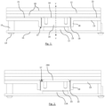
- Figure 1 illustrates a cross section view of a circuit board 11 having an integrated circuit/component 12 upon its surface.
- the circuit board 11 is a support surface for the component 12 and is also fastened to a mounting body, e.g. housing 13, which serves to provide a mounting structure substantially over/above component 12.
- the housing is generally fastened, e.g. by a screw 14 into support legs 15, to circuit board 11 in a non-adjustable (in use) spatial relationship.
- an adjustable heat dissipation device or insert 16 configured to adjustably move relative to component 12, e.g. toward and away from it along an axis A.
- Insert 16 is located within an opening/bore 17 through body 13, that may include upstanding walls 18 to give it additional depth than the substantive planar thickness of body 13.
- insert 16 is a block of thermally transmittive material (e.g. made from any solid high thermal conductive material like aluminium, copper or ceramic) that can convey heat generated by the component 12 away from it and toward the mounting body 13 and a separate heat sink structure 20.
- the mounting body 13 comprises a heat sink facing surface 21 that is in close contact but separable from the heat sink structure 20.
- Common heat sink features such as a coolant path 22 are provided within the heat sink structure 20. However, as is apparent from the figures, the coolant path 22 is partitioned from the mounting body and insert. In this way, separating the heat sink 20 from the mounting body and circuit does not result in leakage or other compromise of the cooling medium.
- a top side of integrated circuit 12 which is the thermal heat source in the present example
- TIM thermal interface material
- the insert 16 can be spatially re-configured relative to component 12, e.g. height adjusted along axis A, so that the TIM layer 23 can be applied as thinly as possible to cover the top side of the integrated circuit 12 in good thermal contact.
- the thermal interface material is not as thermally efficient at conveying heat as the rest of a heat sink structure.
- a substantive outer surface 21 of housing 13 may also be covered in a TIM 25 on the same plane as TIM layer 24, for substantive contact against heat sink 20; however, it is contact in the vicinity of the insert 16 and component 12 which is most critical such that a cooling fluid within channel 22 of heat sink 20 can ultimately remove heat from component 12.
- An adjustment and fixing configuration for the heat spreader device 16 can be implemented in a form fitting way, e.g. a threaded connection between insert 16 and housing 13 as shown in Figures 1 to 3 , or a press fit or adhesive solution as shown in Figure 4 .
- Other material connections are possible such as soldering/welding, once the relative height of insert 16 to minimise the TIM contact gap 23 is set.
- the heat spreader 16 can be made of any solid high thermal conductive material, such as aluminium, copper or ceramic.
- the heat sink 20 may include a closed circuit for a transfer media and/or a solid part, such as cooling fins or a section of a car chassis.
- Figure 1 shows a configuration of the invention adapted to thermally contact with a relatively high component 12
- Figure 2 shows the same embodiment, but configured to thermally contact with a more shallow component 12A.
- the other components are otherwise the same.
- insert 16 protrudes from mounting body 13/walls 18 by virtue of several turns of screw thread 19.
- the same thin layer of TIM 23 can be maintained against lower component 12A.
- the second layer of TIM may be thicker than that of Figure 1 , denoted by numeral 24A.
- the fact that TIM layer 24A is thicker is relatively inconsequential since heat spreader 16 has already acted to reduce thermal density.
- TIM layer 24A is efficient enough to transfer heat to the substantive heat sink 20 and an associated cooling medium.
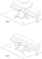
- Figure 3 illustrates a perspective section view of the configuration from Figure 1 , where adjustment thread 19 is visible
- Figure 4 illustrates a variant embodiment where insert 16 may be configured for adjustment by an interference fit (i.e. tight fit between its peripheral walls and inner walls 18 of mounting body 13.
- an interference fit i.e. tight fit between its peripheral walls and inner walls 18 of mounting body 13.
- insert 16 may be glued or soldered/welded in place.
- insert 16 is spatially adjusted relative to an object to be cooled on a supporting surface 11, preferably to achieve a layer of TIM 23 as thin as possible, while the opposite side of insert 16 maintains adequate thermal contact with a separable heat sink structure 20.
- FIG 5 illustrates the adjustable heat spreader embodiment of Figures 1, 2 and 3 , where an alternative separable heat sink structure 20A is thermally contacted, via TIM layers 23 and 25, with the insert and mounting body respectively.
- Heat sink 20A has surface features such as pins/fins for interacting with a cooling medium, e.g. air.
- a cooling medium e.g. air.
- the functionality of adjusting insert 16 relative to its mount 13, in order to minimise (or eliminate) TIM layer 23, is unchanged.
- heat sink 20/20A can be separated from mounting body 13 in order to access insert 16. Insert 16 can likewise be removed to gain access to component 12 underneath.
- the heat sink 20/20A may be attached by any suitable means to fix it in place, including use of the TIM as an adhesive that holds the components together.
- a thermal interface material may provide an adhesive aspect to peripheral walls of the insert in contact with the opening, with or without a thread present.
- the invention entails a dissipater or a heat spreader insert 16 mounted for adjustable movement from a frame support 13 fixed over a support surface 11 having an element 12 to be cooled.
- the element to be cooled may also be regarded as a heating element which is preferably immovable with respect to its support 11.
- the element to be cooled may typically be a chip, a chipset, an integrated circuit (IC), a central processing unit (CPU) or any other semiconductor.
- the element to be cooled is not limited to an electronic component but may also be an electrical element such as a transformer for example.
- the support 11 may be a plate or any element to be assembled relative to a heat sink 20.
- the support 11 is a printed circuit board (PCB). It may relate to a PCB of an electronic control unit (ECU), more particularly a PCB belonging to a vehicle's ECU for instance.
- support and “mount” etc should be maintained, irrespective of the relative sizes of the components.
- the main role of the support 11 is to be assembled to the heat sink 10, via the mounting body, in order to cool the heating element (s) 12 that the support 11 includes.
- the aforementioned support may also be considered to have been so named in reference to the at least one element 12 to be cooled that it carries.
- the present heat sink system is not limited to have a single insert 16 but may include several inserts 16 adjustable from the mounting body 13, relative to a separable heat sink, which can be each adjusted independently from the others. Therefore, if the same support 11 has several elements 12 to be cooled which have elements contact surfaces protruding at different heights above the support 11, the present invention has the ability to adapt to each of the elements 12 of the support 11.
- the heat dissipation structure of the present disclosure is particularly efficient, not only with a support 11 comprising a single component 12 to be cooled, but also with a support 11 comprising a plurality of elements 12(12A), even if those or a part of them protrude at different levels above the support.
- the insert 16 is preferably adjustable along an axis of movement Y-Y that is orthogonal to the support surface 11, more specifically perpendicular, it should be noted that the insert 16 could be adjustable according to an angled movement, for example using inclined sliding grooves arranged within the body 13. In such a case, the insert 16 may be provided with protrusions intended to engage the grooves of the body 13.
- a dovetail profile assembly (inclined e.g. at an acute angle relative to the planar surface of the support 11) may be used for example to move the insert 16 into the body 13, until the insert 16 comes into contact with the element 12 to be cooled or comes close to it.
- the insert 16 may have a shape which is not circular, when seen from above (e.g.
- Such a shape may be a square or rectangular shape for instance.
- the insert 16 may be of non-circular shape in any embodiment that does not require a thread for rotational purposes.
- FIG. 6 A third embodiment of heat spreader configuration is illustrated by Figure 6 .
- the opening 17 through the mounting body 13 may be oversized so as to accommodate lateral movement of the insert 16, e.g. in a direction X.
- insert 16 may be engaged to move over (e.g. horizontally) the surface of component 12 instead of or in addition to movement toward and away (e.g. vertically along direct Y as shown in Figure 1 ) from component 12 as previously described.
- the mechanism by which lateral movement is adjustable is a dovetail guide element 26.
- a dovetail guide element 26 a pair of rails upon which the insert may engage and slide, although other solutions are possible.
- the mechanism generally features engagement between a receiving portion and a guide element.
- insert 16 may be relatively free moving (e.g. in an X or Z direction) within an oversized opening 17 since it is clamped in place by heat sink 20 once fixed in position.
- a receiving portion and guide element may be (additionally or in combination) arranged vertically or at an angle to provide displacement relative to the fixed component.
- opening 17 is generally rectangular with a width dimension to tightly accommodate insert 16, and a longer length, which serves as a track for controlled lateral movement of insert 16.
- Further forms may provide other mechanisms for controlling/constraining lateral and/or vertical movement of an insert 16 within a mounting body 13 relative to a component 12 to be cooled.
- the mounting body 13 may further include a sealing means between the insert 16 and walls of its opening 17, especially if adjustably fitted into the body by means of a push-fit inter-engagement.
- the sealing means is a threaded sealant or a thread lock.
- the sealing means may be an O-ring.
- such an O-ring is intended to protrude at the periphery of the insert 16.
- the sealing means may also prevent any accidental displacement of the insert 16 within the body 13 which may result from vibrations for example.
- the sealing means may also be used to meet ingress protection class requirements, especially against the ingress of dust and/or liquid.
- a glue connection may be arranged between the insert 16 and the body 13/18, instead of or in addition to sealing. Such a glue connection may fixedly position the insert 16 within the body 13, once it has been properly adjusted with respect to the contact surface of the element to be cooled.
- the thermal interface material may be regarded as a gap filler which is mainly used to compensate any flatness deviation of the element contact surface and/or any possible defects between the respective contact surfaces.
- the thermal interface material can also play an adhesive role for assembling the two aforementioned contact surfaces.
- the thermal interface material due to its thermal conductivity properties, the thermal interface material (23, 24, 25) helps to eliminate any remaining interstitial air gaps between respective contact surfaces and helps to evacuate the heat emitted by the heating element 12.
- the thermal interface material may typically consist of a gel, glue, a pad, an adhesive tape or thermal grease for example.
- the insert 16 and heat sink 20 may be made of any suitable thermally conductive material such as aluminium, copper or a combination of any materials for example.
- an adjustable heat spreader which comprises a mounting body for mounting to a circuit board having at least one electronic component to be cooled.
- the mounting body includes an opening into which is fitted a heat spreading insert.
- a contact surface of the insert is able to be brought into contact against the component.
- the mounting body also has a contact surface provided for interfacing with a mechanically separate heat sink.
- a layer of thermal interface material may be applied between the insert and the component, the insert and the heat sink and the mounting body and the heat sink.
- the present disclosure further relates to a printed circuit board 11 in combination with a mounting body 13, non-adjustably mounted together.
- the present disclosure further relates to a vehicle, in particular a motor vehicle, comprising the aforementioned printed circuit board in combination with the mounting body and its adjustable insert.
- vehicle body itself may serve as a separable heat sink.
Landscapes
- Engineering & Computer Science (AREA)
- Physics & Mathematics (AREA)
- Thermal Sciences (AREA)
- Microelectronics & Electronic Packaging (AREA)
- Mechanical Engineering (AREA)
- General Engineering & Computer Science (AREA)
- Cooling Or The Like Of Electrical Apparatus (AREA)
- Cooling Or The Like Of Semiconductors Or Solid State Devices (AREA)
Priority Applications (3)
| Application Number | Priority Date | Filing Date | Title |
|---|---|---|---|
| EP23153311.8A EP4407675B1 (de) | 2023-01-25 | 2023-01-25 | Verstellbarer wärmeverteiler für einen kühlkörper |
| CN202410053538.2A CN118400943A (zh) | 2023-01-25 | 2024-01-15 | 用于散热器的可调节热扩散器 |
| US18/422,102 US20240247884A1 (en) | 2023-01-25 | 2024-01-25 | Adjustable Heat Spreader for a Heat Sink |
Applications Claiming Priority (1)
| Application Number | Priority Date | Filing Date | Title |
|---|---|---|---|
| EP23153311.8A EP4407675B1 (de) | 2023-01-25 | 2023-01-25 | Verstellbarer wärmeverteiler für einen kühlkörper |
Publications (2)
| Publication Number | Publication Date |
|---|---|
| EP4407675A1 true EP4407675A1 (de) | 2024-07-31 |
| EP4407675B1 EP4407675B1 (de) | 2025-08-13 |
Family
ID=85076159
Family Applications (1)
| Application Number | Title | Priority Date | Filing Date |
|---|---|---|---|
| EP23153311.8A Active EP4407675B1 (de) | 2023-01-25 | 2023-01-25 | Verstellbarer wärmeverteiler für einen kühlkörper |
Country Status (3)
| Country | Link |
|---|---|
| US (1) | US20240247884A1 (de) |
| EP (1) | EP4407675B1 (de) |
| CN (1) | CN118400943A (de) |
Citations (1)
| Publication number | Priority date | Publication date | Assignee | Title |
|---|---|---|---|---|
| EP4092720A1 (de) | 2021-05-20 | 2022-11-23 | Aptiv Technologies Limited | Kühlkörper |
Family Cites Families (14)
| Publication number | Priority date | Publication date | Assignee | Title |
|---|---|---|---|---|
| US4345267A (en) * | 1980-03-31 | 1982-08-17 | Amp Incorporated | Active device substrate connector having a heat sink |
| US4448240A (en) * | 1982-12-20 | 1984-05-15 | International Business Machines Corporation | Telescoping thermal conduction element for cooling semiconductor devices |
| GB8601746D0 (en) * | 1986-01-24 | 1986-02-26 | British Telecomm | Heat sink |
| JP2507561B2 (ja) * | 1988-10-19 | 1996-06-12 | 株式会社日立製作所 | 半導体の冷却装置 |
| US5345107A (en) * | 1989-09-25 | 1994-09-06 | Hitachi, Ltd. | Cooling apparatus for electronic device |
| JP2821229B2 (ja) * | 1990-03-30 | 1998-11-05 | 株式会社日立製作所 | 電子回路装置 |
| JPH0786471A (ja) * | 1993-09-20 | 1995-03-31 | Hitachi Ltd | 半導体モジュ−ル |
| JP2926537B2 (ja) * | 1994-12-15 | 1999-07-28 | 株式会社日立製作所 | マルチチップモジュ−ルの冷却装置 |
| JPH1070219A (ja) * | 1996-08-27 | 1998-03-10 | Fujitsu Ltd | 実装モジュールの冷却装置 |
| JPH11354954A (ja) * | 1998-06-10 | 1999-12-24 | Fujitsu Ltd | 電子装置 |
| US6014315A (en) * | 1998-09-08 | 2000-01-11 | Chip Coolers, Inc. | Heat sink assembly with multiple pressure capability |
| US6021045A (en) * | 1998-10-26 | 2000-02-01 | Chip Coolers, Inc. | Heat sink assembly with threaded collar and multiple pressure capability |
| US6695042B1 (en) * | 2002-07-31 | 2004-02-24 | Hewlett-Packard Development Company, L.P. | Adjustable pedestal thermal interface |
| US9736966B1 (en) * | 2016-02-10 | 2017-08-15 | International Business Machines Corporation | Heat sink with integrated threaded lid |
-
2023
- 2023-01-25 EP EP23153311.8A patent/EP4407675B1/de active Active
-
2024
- 2024-01-15 CN CN202410053538.2A patent/CN118400943A/zh active Pending
- 2024-01-25 US US18/422,102 patent/US20240247884A1/en active Pending
Patent Citations (2)
| Publication number | Priority date | Publication date | Assignee | Title |
|---|---|---|---|---|
| EP4092720A1 (de) | 2021-05-20 | 2022-11-23 | Aptiv Technologies Limited | Kühlkörper |
| US20220377945A1 (en) * | 2021-05-20 | 2022-11-24 | Aptiv Technologies Limited | Heat Sink |
Also Published As
| Publication number | Publication date |
|---|---|
| US20240247884A1 (en) | 2024-07-25 |
| EP4407675B1 (de) | 2025-08-13 |
| CN118400943A (zh) | 2024-07-26 |
Similar Documents
| Publication | Publication Date | Title |
|---|---|---|
| KR100281500B1 (ko) | 전자장치를냉각시키기위한장치및방법 | |
| US9480189B2 (en) | Electronic control apparatus | |
| TWI661656B (zh) | 馬達驅動裝置 | |
| US7203065B1 (en) | Heatsink assembly | |
| EP3745235B1 (de) | Mehrzweckkühlkörper, verfahren zu seiner herstellung, platinenkarte und mehrzweckkühlkörperplattform | |
| EP4407675B1 (de) | Verstellbarer wärmeverteiler für einen kühlkörper | |
| US10366939B2 (en) | Heat sink fastening system and method | |
| EP4009362A1 (de) | Thermische verwaltung von elektronischen vorrichtungen auf einer kühlplatte | |
| US20220377945A1 (en) | Heat Sink | |
| US6704197B2 (en) | Electronic unit having desired heat radiation properties | |
| US20040080838A1 (en) | Cooling opto-electronic packages | |
| US12069795B2 (en) | Methods for and apparatuses of a circuit board cooling device | |
| JP2822785B2 (ja) | 電子機器用放熱装置 | |
| JP3564350B2 (ja) | ヒートシンク固定構造および方法 | |
| CN215301026U (zh) | 一种精密电子工程用防水效果好的电路板 | |
| CN121312265A (zh) | 用于机动车的电子构件的散热的装置和方法 | |
| CN223414059U (zh) | 加工治具 | |
| CN220044059U (zh) | 一种两板间恒温高散热屏蔽腔体模块结构 | |
| JPH0442926Y2 (de) | ||
| US20240389272A1 (en) | Method for producing a heat sink | |
| JPH08307077A (ja) | プリント基板実装品およびプリント基板実装ユニット品 | |
| CA2326260A1 (en) | Installation structure of a power circuit unit, installation structure of a circuit board and installation method of a power circuit unit | |
| JPH03292799A (ja) | プリント配線板ユニットの放熱構造 | |
| JPH0445249Y2 (de) | ||
| JPH05152473A (ja) | 集積回路の取付方法および冷却方法 |
Legal Events
| Date | Code | Title | Description |
|---|---|---|---|
| PUAI | Public reference made under article 153(3) epc to a published international application that has entered the european phase |
Free format text: ORIGINAL CODE: 0009012 |
|
| STAA | Information on the status of an ep patent application or granted ep patent |
Free format text: STATUS: THE APPLICATION HAS BEEN PUBLISHED |
|
| AK | Designated contracting states |
Kind code of ref document: A1 Designated state(s): AL AT BE BG CH CY CZ DE DK EE ES FI FR GB GR HR HU IE IS IT LI LT LU LV MC ME MK MT NL NO PL PT RO RS SE SI SK SM TR |
|
| RAP3 | Party data changed (applicant data changed or rights of an application transferred) |
Owner name: APTIV TECHNOLOGIES AG |
|
| STAA | Information on the status of an ep patent application or granted ep patent |
Free format text: STATUS: REQUEST FOR EXAMINATION WAS MADE |
|
| 17P | Request for examination filed |
Effective date: 20241024 |
|
| RBV | Designated contracting states (corrected) |
Designated state(s): AL AT BE BG CH CY CZ DE DK EE ES FI FR GB GR HR HU IE IS IT LI LT LU LV MC ME MK MT NL NO PL PT RO RS SE SI SK SM TR |
|
| GRAP | Despatch of communication of intention to grant a patent |
Free format text: ORIGINAL CODE: EPIDOSNIGR1 |
|
| STAA | Information on the status of an ep patent application or granted ep patent |
Free format text: STATUS: GRANT OF PATENT IS INTENDED |
|
| RIC1 | Information provided on ipc code assigned before grant |
Ipc: H01L 23/367 20060101ALN20250306BHEP Ipc: H01L 23/40 20060101AFI20250306BHEP |
|
| INTG | Intention to grant announced |
Effective date: 20250313 |
|
| RIN1 | Information on inventor provided before grant (corrected) |
Inventor name: REINHOLD, PETER Inventor name: RADEMACHER, FALK |
|
| GRAS | Grant fee paid |
Free format text: ORIGINAL CODE: EPIDOSNIGR3 |
|
| GRAA | (expected) grant |
Free format text: ORIGINAL CODE: 0009210 |
|
| STAA | Information on the status of an ep patent application or granted ep patent |
Free format text: STATUS: THE PATENT HAS BEEN GRANTED |
|
| AK | Designated contracting states |
Kind code of ref document: B1 Designated state(s): AL AT BE BG CH CY CZ DE DK EE ES FI FR GB GR HR HU IE IS IT LI LT LU LV MC ME MK MT NL NO PL PT RO RS SE SI SK SM TR |
|
| REG | Reference to a national code |
Ref country code: GB Ref legal event code: FG4D |
|
| REG | Reference to a national code |
Ref country code: CH Ref legal event code: EP |
|
| REG | Reference to a national code |
Ref country code: DE Ref legal event code: R096 Ref document number: 602023005550 Country of ref document: DE |
|
| P01 | Opt-out of the competence of the unified patent court (upc) registered |
Free format text: CASE NUMBER: UPC_APP_1265_4407675/2025 Effective date: 20250729 |
|
| REG | Reference to a national code |
Ref country code: IE Ref legal event code: FG4D |
|
| REG | Reference to a national code |
Ref country code: DE Ref legal event code: R079 Ref document number: 602023005550 Country of ref document: DE Free format text: PREVIOUS MAIN CLASS: H01L0023400000 Ipc: H10W0040600000 |
|
| REG | Reference to a national code |
Ref country code: NL Ref legal event code: MP Effective date: 20250813 |
|
| PG25 | Lapsed in a contracting state [announced via postgrant information from national office to epo] |
Ref country code: IS Free format text: LAPSE BECAUSE OF FAILURE TO SUBMIT A TRANSLATION OF THE DESCRIPTION OR TO PAY THE FEE WITHIN THE PRESCRIBED TIME-LIMIT Effective date: 20251213 |
|
| PG25 | Lapsed in a contracting state [announced via postgrant information from national office to epo] |
Ref country code: NO Free format text: LAPSE BECAUSE OF FAILURE TO SUBMIT A TRANSLATION OF THE DESCRIPTION OR TO PAY THE FEE WITHIN THE PRESCRIBED TIME-LIMIT Effective date: 20251113 |
|
| REG | Reference to a national code |
Ref country code: LT Ref legal event code: MG9D |
|
| PG25 | Lapsed in a contracting state [announced via postgrant information from national office to epo] |
Ref country code: PT Free format text: LAPSE BECAUSE OF FAILURE TO SUBMIT A TRANSLATION OF THE DESCRIPTION OR TO PAY THE FEE WITHIN THE PRESCRIBED TIME-LIMIT Effective date: 20251215 |
|
| PG25 | Lapsed in a contracting state [announced via postgrant information from national office to epo] |
Ref country code: FI Free format text: LAPSE BECAUSE OF FAILURE TO SUBMIT A TRANSLATION OF THE DESCRIPTION OR TO PAY THE FEE WITHIN THE PRESCRIBED TIME-LIMIT Effective date: 20250813 |
|
| PG25 | Lapsed in a contracting state [announced via postgrant information from national office to epo] |
Ref country code: HR Free format text: LAPSE BECAUSE OF FAILURE TO SUBMIT A TRANSLATION OF THE DESCRIPTION OR TO PAY THE FEE WITHIN THE PRESCRIBED TIME-LIMIT Effective date: 20250813 Ref country code: NL Free format text: LAPSE BECAUSE OF FAILURE TO SUBMIT A TRANSLATION OF THE DESCRIPTION OR TO PAY THE FEE WITHIN THE PRESCRIBED TIME-LIMIT Effective date: 20250813 |
|
| PG25 | Lapsed in a contracting state [announced via postgrant information from national office to epo] |
Ref country code: GR Free format text: LAPSE BECAUSE OF FAILURE TO SUBMIT A TRANSLATION OF THE DESCRIPTION OR TO PAY THE FEE WITHIN THE PRESCRIBED TIME-LIMIT Effective date: 20251114 |
|
| PG25 | Lapsed in a contracting state [announced via postgrant information from national office to epo] |
Ref country code: SE Free format text: LAPSE BECAUSE OF FAILURE TO SUBMIT A TRANSLATION OF THE DESCRIPTION OR TO PAY THE FEE WITHIN THE PRESCRIBED TIME-LIMIT Effective date: 20250813 |
|
| PG25 | Lapsed in a contracting state [announced via postgrant information from national office to epo] |
Ref country code: LV Free format text: LAPSE BECAUSE OF FAILURE TO SUBMIT A TRANSLATION OF THE DESCRIPTION OR TO PAY THE FEE WITHIN THE PRESCRIBED TIME-LIMIT Effective date: 20250813 |
|
| PG25 | Lapsed in a contracting state [announced via postgrant information from national office to epo] |
Ref country code: BG Free format text: LAPSE BECAUSE OF FAILURE TO SUBMIT A TRANSLATION OF THE DESCRIPTION OR TO PAY THE FEE WITHIN THE PRESCRIBED TIME-LIMIT Effective date: 20250813 Ref country code: PL Free format text: LAPSE BECAUSE OF FAILURE TO SUBMIT A TRANSLATION OF THE DESCRIPTION OR TO PAY THE FEE WITHIN THE PRESCRIBED TIME-LIMIT Effective date: 20250813 |
|
| PG25 | Lapsed in a contracting state [announced via postgrant information from national office to epo] |
Ref country code: RS Free format text: LAPSE BECAUSE OF FAILURE TO SUBMIT A TRANSLATION OF THE DESCRIPTION OR TO PAY THE FEE WITHIN THE PRESCRIBED TIME-LIMIT Effective date: 20251113 |
|
| PG25 | Lapsed in a contracting state [announced via postgrant information from national office to epo] |
Ref country code: ES Free format text: LAPSE BECAUSE OF FAILURE TO SUBMIT A TRANSLATION OF THE DESCRIPTION OR TO PAY THE FEE WITHIN THE PRESCRIBED TIME-LIMIT Effective date: 20250813 |
|
| REG | Reference to a national code |
Ref country code: AT Ref legal event code: MK05 Ref document number: 1825693 Country of ref document: AT Kind code of ref document: T Effective date: 20250813 |
|
| PG25 | Lapsed in a contracting state [announced via postgrant information from national office to epo] |
Ref country code: SM Free format text: LAPSE BECAUSE OF FAILURE TO SUBMIT A TRANSLATION OF THE DESCRIPTION OR TO PAY THE FEE WITHIN THE PRESCRIBED TIME-LIMIT Effective date: 20250813 |
|
| PG25 | Lapsed in a contracting state [announced via postgrant information from national office to epo] |
Ref country code: DK Free format text: LAPSE BECAUSE OF FAILURE TO SUBMIT A TRANSLATION OF THE DESCRIPTION OR TO PAY THE FEE WITHIN THE PRESCRIBED TIME-LIMIT Effective date: 20250813 |
|
| PGFP | Annual fee paid to national office [announced via postgrant information from national office to epo] |
Ref country code: DE Payment date: 20251217 Year of fee payment: 4 |
|
| PG25 | Lapsed in a contracting state [announced via postgrant information from national office to epo] |
Ref country code: AT Free format text: LAPSE BECAUSE OF FAILURE TO SUBMIT A TRANSLATION OF THE DESCRIPTION OR TO PAY THE FEE WITHIN THE PRESCRIBED TIME-LIMIT Effective date: 20250813 |
|
| PG25 | Lapsed in a contracting state [announced via postgrant information from national office to epo] |
Ref country code: IT Free format text: LAPSE BECAUSE OF FAILURE TO SUBMIT A TRANSLATION OF THE DESCRIPTION OR TO PAY THE FEE WITHIN THE PRESCRIBED TIME-LIMIT Effective date: 20250813 |
|
| PGFP | Annual fee paid to national office [announced via postgrant information from national office to epo] |
Ref country code: FR Payment date: 20260107 Year of fee payment: 4 |
|
| PG25 | Lapsed in a contracting state [announced via postgrant information from national office to epo] |
Ref country code: CZ Free format text: LAPSE BECAUSE OF FAILURE TO SUBMIT A TRANSLATION OF THE DESCRIPTION OR TO PAY THE FEE WITHIN THE PRESCRIBED TIME-LIMIT Effective date: 20250813 |
|
| PG25 | Lapsed in a contracting state [announced via postgrant information from national office to epo] |
Ref country code: SK Free format text: LAPSE BECAUSE OF FAILURE TO SUBMIT A TRANSLATION OF THE DESCRIPTION OR TO PAY THE FEE WITHIN THE PRESCRIBED TIME-LIMIT Effective date: 20250813 Ref country code: EE Free format text: LAPSE BECAUSE OF FAILURE TO SUBMIT A TRANSLATION OF THE DESCRIPTION OR TO PAY THE FEE WITHIN THE PRESCRIBED TIME-LIMIT Effective date: 20250813 |