EP4407802A1 - Antennenvorrichtung - Google Patents
Antennenvorrichtung Download PDFInfo
- Publication number
- EP4407802A1 EP4407802A1 EP23168471.3A EP23168471A EP4407802A1 EP 4407802 A1 EP4407802 A1 EP 4407802A1 EP 23168471 A EP23168471 A EP 23168471A EP 4407802 A1 EP4407802 A1 EP 4407802A1
- Authority
- EP
- European Patent Office
- Prior art keywords
- waveguide
- antenna
- antenna apparatus
- horn antenna
- iris
- Prior art date
- Legal status (The legal status is an assumption and is not a legal conclusion. Google has not performed a legal analysis and makes no representation as to the accuracy of the status listed.)
- Granted
Links
Images







Classifications
-
- H—ELECTRICITY
- H01—ELECTRIC ELEMENTS
- H01Q—ANTENNAS, i.e. RADIO AERIALS
- H01Q13/00—Waveguide horns or mouths; Slot antennas; Leaky-waveguide antennas; Equivalent structures causing radiation along the transmission path of a guided wave
- H01Q13/02—Waveguide horns
- H01Q13/0208—Corrugated horns
-
- H—ELECTRICITY
- H01—ELECTRIC ELEMENTS
- H01Q—ANTENNAS, i.e. RADIO AERIALS
- H01Q13/00—Waveguide horns or mouths; Slot antennas; Leaky-waveguide antennas; Equivalent structures causing radiation along the transmission path of a guided wave
- H01Q13/02—Waveguide horns
- H01Q13/0208—Corrugated horns
- H01Q13/0216—Dual-depth corrugated horns
-
- H—ELECTRICITY
- H01—ELECTRIC ELEMENTS
- H01P—WAVEGUIDES; RESONATORS, LINES, OR OTHER DEVICES OF THE WAVEGUIDE TYPE
- H01P3/00—Waveguides; Transmission lines of the waveguide type
- H01P3/12—Hollow waveguides
- H01P3/123—Hollow waveguides with a complex or stepped cross-section, e.g. ridged or grooved waveguides
-
- H—ELECTRICITY
- H01—ELECTRIC ELEMENTS
- H01Q—ANTENNAS, i.e. RADIO AERIALS
- H01Q13/00—Waveguide horns or mouths; Slot antennas; Leaky-waveguide antennas; Equivalent structures causing radiation along the transmission path of a guided wave
- H01Q13/02—Waveguide horns
- H01Q13/0275—Ridged horns
-
- H—ELECTRICITY
- H01—ELECTRIC ELEMENTS
- H01Q—ANTENNAS, i.e. RADIO AERIALS
- H01Q5/00—Arrangements for simultaneous operation of antennas on two or more different wavebands, e.g. dual-band or multi-band arrangements
- H01Q5/30—Arrangements for providing operation on different wavebands
- H01Q5/378—Combination of fed elements with parasitic elements
- H01Q5/392—Combination of fed elements with parasitic elements the parasitic elements having dual-band or multi-band characteristics
-
- H—ELECTRICITY
- H01—ELECTRIC ELEMENTS
- H01Q—ANTENNAS, i.e. RADIO AERIALS
- H01Q13/00—Waveguide horns or mouths; Slot antennas; Leaky-waveguide antennas; Equivalent structures causing radiation along the transmission path of a guided wave
- H01Q13/02—Waveguide horns
- H01Q13/025—Multimode horn antennas; Horns using higher mode of propagation
- H01Q13/0258—Orthomode horns
Definitions
- Example embodiments of the present disclosure relate to an antenna apparatus.
- An antenna apparatus is a configuration that is requisite for wireless communication and may transmit information over a long distance in a form of electromagnetic waves with a predetermined frequency.
- high gain and a feature such as beam-steering may be required for the antenna apparatus.
- an antenna may be designed as an array.
- the spacing between the arrays it is advantageous for the spacing between the arrays to be half or less than the wavelength of the electromagnetic wave transmitted. To satisfy this, miniaturization of the antenna apparatus is required. Also, if it is possible to transmit signals of multiple frequency bands with a single antenna apparatus, the effect of multiple antenna apparatuses may be achieved with the single antenna apparatus.
- An aspect provides a structure for an antenna apparatus with a simple impedance matching design by enabling a miniaturization of a horn antenna, which is introduced as a coaxial structure.
- an antenna apparatus including a waveguide that extends in a first direction, an opening portion having a corrugated shape and attached to the waveguide in a second direction different from the first direction, and a horn antenna including at least one ridge and provided in the waveguide as a structure coaxial with the waveguide.
- the horn antenna may be configured to pass a first signal of a relatively high frequency band.
- a second signal of a frequency band lower than that of the first signal may pass through a space between the waveguide and the horn antenna.
- the antenna apparatus may further include at least one first iris structure that protrudes from an outer circumferential surface of the horn antenna in a direction to the waveguide.
- the first iris structure and the ridge may be provided as a plurality of first iris structures and a plurality of ridges.
- the antenna apparatus may further include a conduit provided in the horn antenna as a structure coaxial with the horn antenna to pass the first signal.
- the ridge may include a first portion corresponding to at least one structure recessed at a predetermined depth and formed in the first direction and a second portion of at least one side of the first portion.
- the antenna apparatus may further include a second iris structure that protrudes from an inner circumferential surface of the horn antenna in a radial direction toward a central axis of the horn antenna along a plane intersecting the first direction.
- the first portion and the second iris structure may be provided as a plurality of first portions and a plurality of second iris structures.
- an apparatus including an antenna apparatus configured to transmit a first signal and a second signal having different frequency bands, a turnstile connected to one side of the antenna apparatus, a first polarizer configured to pass the first signal at one side of the turnstile, an ortho-mode transducer (OMT) used for feeding of the first signal at one side of the first polarizer, and a second polarizer connected to the other side of the turnstile to pass the second signal.
- an antenna apparatus configured to transmit a first signal and a second signal having different frequency bands
- a turnstile connected to one side of the antenna apparatus
- a first polarizer configured to pass the first signal at one side of the turnstile
- an ortho-mode transducer OHT
- an antenna apparatus with a simple impedance matching design by enabling a miniaturization of a horn antenna, which is introduced as a coaxial structure.
- by reducing a height of an iris structure and a number of iris structures applied it is possible to improve the design and fabrication convenience of the antenna apparatus in terms of impedance matching design.
- the expression "at least one of A, B, and C” may include the following meaning: A alone; B alone; C alone; both A and B together; both A and C together; both B and C together; or all three of A, B, and C together.
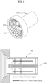
- FIG. 1 is a diagram illustrating an antenna apparatus according to an example embodiment of the present disclosure.
- an antenna apparatus may include a waveguide 130, a corrugated opening portion 110 attached to one side surface of a waveguide for obtaining a high gain, and a horn antenna 120 provided in the waveguide 130 as a structure coaxial with the waveguide 130 and includes at least one ridge.
- the antenna apparatus may further include a conduit 140 provided in the horn antenna 120 as a structure coaxial with the horn antenna 120 to pass a first signal.
- the antenna apparatus may pass the first signal of a relatively high frequency band through the horn antenna 120 and pass a second signal of a relatively low frequency band through a space between the waveguide 130 and the horn antenna 120.
- the first signal may be a signal of a K- or Ka-band corresponding to a relatively high frequency
- the second signal may be a signal of an X-band corresponding to a relatively low frequency. Accordingly, the antenna apparatus may be used to transmit and receive signals of multiple bands.
- the horn antenna may include at least one ridge.
- the ridge may prevent an increase in cut-off frequency, which is caused by a miniaturization of the conduit 140 in the horn antenna.
- the horn antenna including the ridge will be described in detail with reference to the drawings below.
- FIG. 2 is a diagram illustrating different structures of an antenna apparatus according to an example embodiment of the present disclosure.
- an image 210 represents a case in which a non-miniaturized antenna is located in a waveguide
- an image 220 represents a case in which a ridged and miniaturized horn antenna is located in the waveguide.
- the antenna apparatus shown in the image 210 may be designed in consideration of a cut-off frequency of the waveguide and thus, restricted on miniaturization.
- the horn antenna that is coaxial with the waveguide may serve as a common axis.
- an antenna return loss may be determined based on a ratio between a radius a from the horn antenna and a radius b from an inner circumferential surface of the waveguide.
- the antenna apparatus may further include at least one iris structure that protrudes from a coaxial direction to a waveguide direction.
- the antenna apparatus may include, for example, six iris structures having different lengths, and as shown the image 220, the antenna apparatus may include, for example, five iris structures having different lengths. That is, by using the ridged horn antenna located in the antenna apparatus, the radius a may be reduced so a return loss of the antenna apparatus may be alleviated. Accordingly, in an impedance matching design of a plurality of iris structures as illustrated in FIG. 4 , heights and/or a number of iris structures may be reduced, which may improve ease and convenience of designing and manufacturing the antenna apparatus.
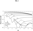
- FIG. 3 is a diagram illustrating a return loss of an antenna according to an example embodiment of the present disclosure.
- a of FIG. 3 denotes a radius from a horn antenna like the radius a of FIG. 2
- b denotes a radius of an entire antenna apparatus, which is a radius from an inner circumferential surface of a waveguide.
- K is a wave number
- a/b represents a return loss of 0 to 0.8. That is, as the radius a increases, the return loss of the antenna apparatus may increase.
- a miniaturized structure for reducing the radius a may be required.
- a case in which a/b is 0.3 may correspond to the image 210
- a case in which a/b is 0.1 may correspond to the image 220.
- the radius a may be reduced, which may alleviate the return loss of the antenna apparatus.
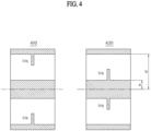
- FIG. 4 is a diagram illustrating an iris structure for alleviating a return loss deterioration according to an example embodiment of the present disclosure.
- a return loss deterioration may occur.
- a sophisticated impedance matching design may be embodied using a plurality of iris structures as shown in images 410 and 420.
- the antenna apparatus as shown in the image 210 may be restricted on miniaturization so an iris impedance matching design may be embodied based on a complicated coaxial structure.
- heights and/or a number of iris structures may be reduced, which may lead to an ease of designing the antenna apparatus of the image 220.
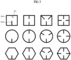
- FIG. 5 is a diagram illustrating various shapes of a waveguide of a horn antenna according to example embodiments of the present disclosure.
- a horn antenna may include a waveguide 510 having a hollow pillar shape and extends in a first direction.
- the waveguide 510 may have various shapes.
- FIG. 5 illustrates a cross-section taken by cutting the waveguide 510 along a plane orthogonal to the first direction.
- the waveguide 510 may have a hollow polygonal column or a hollow cylindrical shape.
- the waveguide 510 may be provided as a plurality of waveguides.
- the plurality of waveguides 510 may be arranged in a form of an array having preset intervals (for example, designed as an array).
- a distance between the plurality of waveguides 510 arranged in a form of an array may be, for example, less than or equal to half a wavelength of an electromagnetic wave transmitted.
- the horn antenna according to example embodiments of the present disclosure may further include at least one ridge 520 protruding from an inner circumferential surface (or inner wall) 511 of the waveguide 510.
- the ridge 520 may extend along the inner circumferential surface 511 of the waveguide 510 in the first direction.
- the ridge 520 may have a rectangular cross-section in view of a cross-section according to FIG. 5 .
- the ridge 520 may be provided as a plurality of ridges 520.
- lengths in a radial direction for example, a direction from the inner circumferential surface 511 of the waveguide 510 toward the central axis of the waveguide 510) of the ridges 520 may be substantially the same.
- the two ridges 520 may be provided to face each other.
- the three ridges 520 may be provided to be at an angle of about 520 degrees (°).
- the four ridges 520 may be provided to be at an angle of about 90°.
- each of the ridges 520 may face another one of the ridges 520.
- the horn antenna may further include a horn portion extending from one end portion of the waveguide 510 in the first direction and has a radius increasing in the first direction (that is, having a cone shape).
- FIG. 6 is a graph illustrating a change in cut-off frequency based on a length of a ridge of a horn antenna according to example embodiments of the present disclosure.
- a horizontal axis represents a ratio (for example, a normalized ridge length) of a length of a ridge in a radial direction to a radius of a waveguide of a horn antenna
- a vertical axis represents a ratio (that is, a normalized cut-off frequency) of a cut-off frequency of a fundamental mode of a horn antenna including a ridge to a cut-off frequency of a horn antenna with no ridge.
- FIG. 6 shows measurement results obtained for a horn antenna including four ridges and a waveguide having a hollow cylindrical shape.
- a length of each of the ridges in a circumferential direction (for example, a rotating direction along an outer circumferential surface or inner circumferential surface of the waveguide on a plane intersecting the first direction) of the waveguide may be about 0.1 times a radius of the waveguide.
- the cut-off frequency may decrease.
- the normalized cut-off frequency may be from about 0.5 to 0.7.
- the horn antenna may be easily miniaturized. Through this, the miniaturized horn antenna may easily suppress unintended grating lobes during beam steering.
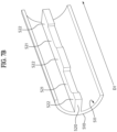
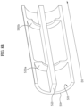
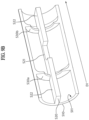
- FIGS. 7A , 7B , 8A , 8B , 9A , and 9B illustrate different impedance-matching structures related to horn antennas.
- FIGS. 7A and 7B illustrate a horn antenna including a ridge to which a plurality of recessed grooves are applied
- FIGS. 8A and 8B illustrate a horn antenna having a plurality of iris structures
- FIGS. 9A and 9B illustrate a horn antenna obtained by combining the horn antennas of FIGS. 7A , 7B , 8A , and 8B .
- each structure will be described in detail with reference to the corresponding drawing.
- FIGS. 7A and 7B are cross-sectional perspective views illustrating a horn antenna according to example embodiments of the present disclosure.
- a recessed groove may also be referred to as one of a recessed portion of the ridge 520 and a concave portion of the ridge 520.
- a horn antenna may include a waveguide 510 having a hollow pillar shape and extends in a first direction D1 and a ridge 520 protruding from an inner circumferential surface 511 of the waveguide 510 in a radial direction of the waveguide 510 and extends in the first direction D1.
- the ridge 520 may have at least one recessed groove formed in the first direction D 1.
- the recessed groove may be a portion of the ridge 520 and configured to concavely recess from a surface in a direction toward a central axis of the waveguide 510.
- the recessed groove may be a portion of the ridge 520 and configured to recess at a predetermined depth in the direction toward the central axis of the waveguide 510.
- a shape of the recessed portion may be as shown in FIG. 7A or 7B . Accordingly, as shown in FIGS. 7A and 7B , due to the recessed structure, a first portion 521 and a second portion 522 may have different lengths from the inner circumferential surface 511 of the waveguide 510 in the direction toward the central axis of the waveguide 510.
- the ridge 520 may include the first portion 521 and the second portion 522 at one side of the first portion 521 corresponding to at least one recessed structure formed in the first direction.
- a length of the first portion 521 in the radial direction may be less than a length of the second portion 522 in the radial direction.
- the length of the second portion 522 in the radial direction may be about 0.6 times to about 0.9 times the radius of the waveguide 510, and the length of the first portion 521 in the radial direction may be less than the length of the second portion 522 in the radial direction and may be about 0.05 times to about 0.3 times the radius of the waveguide 510.
- the first portion 521 having the recessed portion may be provided as a plurality of first portions 521.
- the first portions 521 may be spaced apart from each other in the first direction D1.
- the first portions 521 may have different lengths in the radial direction. That is, the first portions 521 may be recessed at different depths in the radial direction.
- the lengths of the first portions 521 in the radial direction may increase in the first direction D1.
- Each of the lengths of the first portions 521 in the radial direction may be, for example, about 0.3 times to about 0.85 times the radius of the waveguide 510.
- the first portions 521 may have different lengths in the first direction D1.
- the lengths of the first portions 521 in the first direction D1 may decrease in the first direction D1.
- Each of the lengths of the first portions 521 in the first direction D1 may be, for example, about 1.1 times to about 1.8 times the radius of the waveguide 510.
- the horn antenna may be manufactured using, for example, a three-dimensional (3D) printing method. More specifically, according to example embodiments of the present disclosure, the horn antenna may be manufactured using an additive manufacturing method. In this case, an additive manufacturing direction may be, for example, opposite to the first direction D1. Accordingly, referring to FIG. 7B , in each of the first portions 521 of the ridge 520, at least a portion of a surface in the direction toward the central axis of the waveguide 510 may have a curved shape.
- each of the first portions 521 of the ridge 520 may have a length in the radial direction which increases as being closer to the second portion 522 (that is, decreases in the first direction D1).
- a portion of the ridge 520 of which the length in the radial direction changes may support structures inside the waveguide 510 in an additive manufacturing process, which may increase an ease in manufacturing the horn antenna according to example embodiments of the present disclosure.
- FIGS. 8A and 8B are cross-sectional perspective views illustrating a horn antenna according to example embodiments of the present disclosure.
- content substantially the same as described with reference to FIGS. 7A and 7B will be omitted, and a difference thereof will be described in detail.
- a horn antenna may include the waveguide 510 having a hollow pillar shape and extends in the first direction D1, the ridge 520 protruding from the inner circumferential surface 511 of the waveguide 510 in the radial direction of the waveguide 510 and extends in the first direction D1, and iris structures 530a and 530b protrudingfrom the inner circumferential surface 511 of the waveguide 510 along a plane intersecting the first direction D1. That is, the iris structures 530a and 530b protrudingfrom the inner circumferential surface of the horn antenna in the radial direction toward the central axis of the horn antenna along the plane intersecting the first direction may be further included.
- the iris structures 530a and 530b may be shaped as, for example, a ring extending along the inner circumferential surface 511 of the waveguide 510.
- the iris structures 530a and 530b may include the iris structure 530a and the iris structure 530b.
- the iris structure 530a and the iris structure 530b may be spaced apart from each other in the first direction D1.
- a length of each of the iris structure 530a and the iris structure 530b in the radial direction may be less than the length of the ridge 520 in the radial direction.
- the length of the ridge 520 in the radial direction may be about 0.6 times to about 0.9 times the radius of the waveguide 510
- the length of each of the iris structure 530a and the iris structure 530b in the radial direction may be about 0.2 times to about 0.6 times the radius of the waveguide 510.
- the iris structure 530a and the iris structure 530b may have different lengths in the radial direction.
- the length of the iris structure 530a in the radial direction may be greater than the length of the iris structure 530b in the radial direction.
- the lengths of the iris structures 530a and 530b in the radial direction may decrease in the first direction D1.
- the iris structure 530a and the iris structure 530b may have different lengths in the first direction D1.
- the horn antenna may be manufactured using an additive manufacturing method.
- an additive manufacturing direction may be, for example, opposite to the first direction D1.
- each of the iris structures 530a and 530b may have at least a portion of which a length in the radial direction decreases in the first direction D1.
- a portion of each of the iris structures 530a and 530b of which the length in the radial direction changes may support structures inside the waveguide 510 in an additive manufacturing process, which may increase an ease in manufacturing the horn antenna according to example embodiments of the present disclosure.
- FIGS. 9A and 9B are cross-sectional perspective views illustrating a horn antenna according to example embodiments of the present disclosure.
- a recessed groove may also be referred to as one of a recessed portion of the ridge 520 and a concave portion of the ridge 520.
- a horn antenna may include the waveguide 510 having a hollow pillar shape and extends in the first direction D1, the ridge 520 protrudingfrom the inner circumferential surface 511 of the waveguide 510 in the radial direction of the waveguide 510 and extends in the first direction D1, and the iris structures 530a and 530b protrudingfrom the inner circumferential surface 511 of the waveguide 510 along a plane intersecting the first direction D1.
- the ridge 520 may have at least one recessed groove formed in the first direction D1.
- the recessed groove may be a portion of the ridge 520 and configured to concavely recess from the surface in the direction toward the central axis of the waveguide 510.
- the recessed groove may be a portion of the ridge 520 and configured to recess at a predetermined depth in the direction toward the central axis of the waveguide 510.
- a shape of the recessed portion may be as shown in FIG. 9A or 9B . Accordingly, as shown in FIGS. 9A and 9B , due to the recessed structure, the first portion 521 and the second portion 522 may have different lengths from the inner circumferential surface 511 of the waveguide 510 in the direction toward the central axis of the waveguide 510.
- the ridge 520 may include the first portion 521 and the second portion 522 at one side of the first portion 521 corresponding to at least one recessed structure formed in the first direction.
- the iris structure 530a and the iris structure 530b may be spaced apart from each other in the first direction D1.
- Each of the iris structure 530a and the iris structure 530b may extend from a side surface of the second portion 522 of the ridge 520 in the circumferential direction of the waveguide 510.
- the first portion 521 of the ridge 520 may be disposed between the iris structure 530a and the iris structure 530b and spaced apart from each of the iris structure 530a and the iris structure 530b in the first direction D1.
- the length of the first portion 521 of the ridge 520 in the radial direction may be less than the length of the second portion 522 of the ridge 520 in the radial direction.
- the length of the first portion 521 of the ridge 520 in the radial direction may be less than the length of each of the iris structure 530a and the iris structure 530b in the radial direction.
- the length of the first portion 521 of the ridge 520 in the radial direction may be less than the length of the iris structure 530a in the radial direction and greater than the length of the iris structure 530b in the radial direction.
- the length of the first portion 521 of the ridge 520 in the radial direction may be greater than the length of each of the iris structure 530a and the iris structure 530b in the radial direction.
- the horn antenna may be manufactured using an additive manufacturing method.
- an additive manufacturing direction may be, for example, opposite to the first direction D1.
- at least a portion of a plane in the direction toward the central axis of the waveguide 510 may have a curved shape.
- at least a portion of the first portion 521 of the ridge 520 may have a length in the radial direction which increases as being closer to the second portion 522 (that is, decreases in the first direction D1).
- at least a portion of each of the iris structures 530a and 530b may have a length in the radial direction which decreases in the first direction D1.
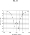
- FIGS. 10A and 10B are graphs illustrating a change in return loss based on a frequency of a horn antenna according to example embodiments of the present disclosure.
- a horizontal axis represents a ratio (that is, a normalized frequency) of a measurement frequency to a sampling frequency
- a vertical axis represents a return loss.
- the return loss may be represented in units of decibels (dB).
- FIG. 10A shows measurement results obtained in a case in which each of a sum of a number of recessed grooves described with reference to FIGS. 7A and 7B and a sum of a number of iris structures described with reference to FIGS. 8A and 8B each are two (that is, a two-stage impedance matching structure).
- FIG. 10B shows measurement results obtained in a case in which a sum of the number of recessed grooves and the number of iris structures is three that is, a three-stage impedance matching structure) as described with reference to FIGS. 9A and 9B .
- the graph in the case of the two-stage impedance matching structure, the graph has two peaks, and in the case of the three-stage impedance matching structure, the graph has three peaks. Accordingly, a bandwidth of the three-stage impedance matching structure (about 20%) may be greater than a bandwidth of the two-stage impedance matching structure (about 8%) based on the return loss of about 15 dB. In other words, as the number (that is, the number of stages) of the impedance matching structures increases, the return loss of the horn antenna according to an example embodiment of the present disclosure may decrease, and thus the bandwidth may increase.
- the horn antenna according to example embodiments of the present disclosure may not only achieve high-power transmission, but also possess broadband characteristics resulting from an increased number of impedance matching structures so it may be used as an antenna array for military satellite communications or as an antenna for radar/electronic warfare systems.
- a military satellite including the horn antenna according to example embodiments of the present disclosure may increase a transmission capacity through an application of frequency band expansion and high-order modulation schemes. As a result, they can maintain excellent communication quality even in adverse radio wave environments, ensuring information exchange between surveillance and reconnaissance systems, command and control systems, precision strike systems, and tactical maneuvers. As a result, an excellent communication quality may be maintained even in an adverse radio wave environment while ensuring surveillance and reconnaissance, command and control, information exchange between precision strike systems, and command and control between tactical maneuvers.
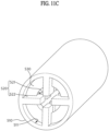
- FIGS. 11A , 11B , and 11C are perspective views illustrating a cross-section of a waveguide of a horn antenna according to example embodiments of the present disclosure.
- content substantially the same as described with reference to FIG. 7A , 7B , 8A , 8B , 9A , and 9B will be omitted, and a difference thereof will be described in detail.
- FIGS. 11A , 11B , and 11C illustrate various types of miniaturized horn antennas having ridges and disposed in an antenna apparatus.
- the horn antennas with the ridges may correspond to an impedance matching structure using a plurality of recesses on an inside ridge according to impedance non-matching due to miniaturization (as shown in FIG. 11A ), a matching structure using an iris structure (as shown in FIG. 11B ), and a matching structure based on a combination of a recess and an iris structure (as shown in FIG. 11C ).
- the horn antenna may include the waveguide 510 extending in the first direction and four ridges 520 protruding from the inner circumferential surface 511 of the waveguide 510 in the radial direction of the waveguide 510.
- each of the ridges 520 may have at least one recessed groove formed in the first direction D1.
- each of the ridges 520 may include the first portion 521 having the recessed groove and the second portion 522 at one side of the first portion 521.
- the recessed portions of the ridges 520 may be provided to be symmetric based on the central axis of the waveguide 510.
- the horn antenna may further include an iris structure 530 protruding from the inner circumferential surface 511 of the waveguide 510 along a plane intersecting the first direction D1.
- Each of the recessed groove and the iris structure 530 may serve as an inductor or capacitor in circuitry, and according to this, the impedance non-matching due to the miniaturization of the horn antenna may be solved.
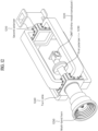
- FIG. 12 illustrates an application of an antenna apparatus according to an example embodiment of the present disclosure.
- a multi-band horn 1250 transmitting a first signal and a second signal of different frequency bands may correspond to an antenna apparatus.
- a turnstile 1240 may be connected to one side of the antenna apparatus 1250.
- a first polarizer 1230 for circularly polarizing the first signal of a relatively high frequency band and an ortho-mode transducer (OMT) 1220 for feeding of the first signal may be sequentially mounted on one side of the turnstile 1240.
- a second polarizer 1210 for polarizing the second signal of a relatively low frequency band may be mounted on the other side of the turnstile 1240.
- an input port of a signal of a K- or Ka-band may be separated by the ortho-mode transducer 1220.
Landscapes
- Waveguide Aerials (AREA)
Applications Claiming Priority (1)
| Application Number | Priority Date | Filing Date | Title |
|---|---|---|---|
| KR1020230009694A KR102556438B1 (ko) | 2023-01-25 | 2023-01-25 | 안테나 장치 |
Publications (2)
| Publication Number | Publication Date |
|---|---|
| EP4407802A1 true EP4407802A1 (de) | 2024-07-31 |
| EP4407802B1 EP4407802B1 (de) | 2025-10-29 |
Family
ID=86328490
Family Applications (1)
| Application Number | Title | Priority Date | Filing Date |
|---|---|---|---|
| EP23168471.3A Active EP4407802B1 (de) | 2023-01-25 | 2023-04-18 | Antennenvorrichtung |
Country Status (3)
| Country | Link |
|---|---|
| US (1) | US20240250442A1 (de) |
| EP (1) | EP4407802B1 (de) |
| KR (1) | KR102556438B1 (de) |
Families Citing this family (1)
| Publication number | Priority date | Publication date | Assignee | Title |
|---|---|---|---|---|
| US12609454B1 (en) * | 2024-05-24 | 2026-04-21 | Caes Systems Llc | Linear horn antenna with conical collar |
Citations (4)
| Publication number | Priority date | Publication date | Assignee | Title |
|---|---|---|---|---|
| US20020163401A1 (en) * | 2001-05-01 | 2002-11-07 | Zhang Henry Z. | Wideband coaxial orthogonal-mode junction coupler |
| US20090179809A1 (en) * | 2008-01-14 | 2009-07-16 | Cheng-Geng Jan | Dual frequency feed assembly |
| WO2017001856A1 (en) * | 2015-06-30 | 2017-01-05 | Global Invacom Ltd | Improvements to receiving and/or transmitting apparatus for satellite transmitted data |
| CN106785469B (zh) * | 2016-12-02 | 2020-12-25 | 航天恒星科技有限公司 | 双频同轴馈源及具有其的天线 |
Family Cites Families (7)
| Publication number | Priority date | Publication date | Assignee | Title |
|---|---|---|---|---|
| JP2000201013A (ja) * | 1999-01-06 | 2000-07-18 | Alps Electric Co Ltd | フィ―ドホ―ン |
| EP1158597A1 (de) * | 2000-05-23 | 2001-11-28 | Newtec cy. | Ka/Ku Doppelband-Speisehorn und Polarisationsweiche |
| US7236681B2 (en) * | 2003-09-25 | 2007-06-26 | Prodelin Corporation | Feed assembly for multi-beam antenna with non-circular reflector, and such an assembly that is field-switchable between linear and circular polarization modes |
| KR101132729B1 (ko) * | 2010-08-25 | 2012-04-06 | (주)하이게인안테나 | 2중 대역 위성통신용 추적 안테나장치 |
| KR101444659B1 (ko) * | 2013-10-04 | 2014-09-24 | 국방과학연구소 | 3중 대역 위성 통신용 안테나 시스템 |
| WO2017137224A1 (en) * | 2016-02-12 | 2017-08-17 | Telefonaktiebolaget Lm Ericsson (Publ) | A transition arrangement comprising a contactless transition or connection between an siw and a waveguide or an antenna |
| KR20180055489A (ko) * | 2016-11-17 | 2018-05-25 | 한국전자통신연구원 | 광대역 고성능 모노펄스 추적 성능을 갖는 코러게이트 혼 |
-
2023
- 2023-01-25 KR KR1020230009694A patent/KR102556438B1/ko active Active
- 2023-04-12 US US18/133,715 patent/US20240250442A1/en active Pending
- 2023-04-18 EP EP23168471.3A patent/EP4407802B1/de active Active
Patent Citations (4)
| Publication number | Priority date | Publication date | Assignee | Title |
|---|---|---|---|---|
| US20020163401A1 (en) * | 2001-05-01 | 2002-11-07 | Zhang Henry Z. | Wideband coaxial orthogonal-mode junction coupler |
| US20090179809A1 (en) * | 2008-01-14 | 2009-07-16 | Cheng-Geng Jan | Dual frequency feed assembly |
| WO2017001856A1 (en) * | 2015-06-30 | 2017-01-05 | Global Invacom Ltd | Improvements to receiving and/or transmitting apparatus for satellite transmitted data |
| CN106785469B (zh) * | 2016-12-02 | 2020-12-25 | 航天恒星科技有限公司 | 双频同轴馈源及具有其的天线 |
Non-Patent Citations (1)
| Title |
|---|
| DAVIS I M ET AL: "A simplified simultaneous X/Ka-band feed-system design", MILITARY COMMUNICATIONS CONFERENCE, 2008. MILCOM 2008. IEEE, IEEE, PISCATAWAY, NJ, USA, 16 November 2008 (2008-11-16), pages 1 - 5, XP031407863, ISBN: 978-1-4244-2676-8 * |
Also Published As
| Publication number | Publication date |
|---|---|
| EP4407802B1 (de) | 2025-10-29 |
| US20240250442A1 (en) | 2024-07-25 |
| KR102556438B1 (ko) | 2023-07-18 |
Similar Documents
| Publication | Publication Date | Title |
|---|---|---|
| US7224320B2 (en) | Small wave-guide radiators for closely spaced feeds on multi-beam antennas | |
| US10218076B1 (en) | Hexagonal waveguide based circularly polarized horn antennas | |
| US7646263B1 (en) | Tracking feed for multi-band operation | |
| CA2423489C (en) | Dual band multimode coaxial tracking feed | |
| US8487826B2 (en) | Multi-band antenna for simultaneously communicating linear polarity and circular polarity signals | |
| US10297917B2 (en) | Dual KA band compact high efficiency CP antenna cluster with dual band compact diplexer-polarizers for aeronautical satellite communications | |
| JP6463092B2 (ja) | デュアルバンド同軸アンテナフィードのためのマッチング及びパターン制御 | |
| CN114520418B (zh) | 具有非对称辐射图案的双极化喇叭天线 | |
| CN112714982A (zh) | 具有设置有脊部的多个波导器件的射频部件 | |
| EP0456034A2 (de) | Doppelkonus-Antenne mit halbkugelförmiger Strahlungscharakteristik | |
| US6653984B2 (en) | Electronically scanned dielectric covered continuous slot antenna conformal to the cone for dual mode seeker | |
| EP4407802A1 (de) | Antennenvorrichtung | |
| CN115241643B (zh) | 基于K、Ka波段的高隔离度双圆极化天线 | |
| US7321277B2 (en) | Waveguide directional filter | |
| EP4325666A1 (de) | Antennenvorrichtung | |
| US20250286282A1 (en) | Antenna apparatus | |
| EP4528919A1 (de) | Kreuzförmiger speiseverbinder, ortho-modus-wandler und antenne | |
| US11121445B2 (en) | Resonator for radio frequency signals | |
| CN120414085B (zh) | 一种基于三维封装集成的滤波贴片天线 | |
| CN119340676B (zh) | 基于模式叠加法的小型同极化全双工天线 | |
| EP4496116A1 (de) | Orthomodaler wandler und duallinear polarisierte speisequelle | |
| JPH05226923A (ja) | 円環マイクロストリップアンテナ | |
| HK40068029A (en) | Dual polarized horn antenna with asymmetric radiation pattern | |
| CN121484430A (zh) | 车载天线以及车辆 |
Legal Events
| Date | Code | Title | Description |
|---|---|---|---|
| PUAI | Public reference made under article 153(3) epc to a published international application that has entered the european phase |
Free format text: ORIGINAL CODE: 0009012 |
|
| STAA | Information on the status of an ep patent application or granted ep patent |
Free format text: STATUS: REQUEST FOR EXAMINATION WAS MADE |
|
| 17P | Request for examination filed |
Effective date: 20230418 |
|
| AK | Designated contracting states |
Kind code of ref document: A1 Designated state(s): AL AT BE BG CH CY CZ DE DK EE ES FI FR GB GR HR HU IE IS IT LI LT LU LV MC ME MK MT NL NO PL PT RO RS SE SI SK SM TR |
|
| GRAP | Despatch of communication of intention to grant a patent |
Free format text: ORIGINAL CODE: EPIDOSNIGR1 |
|
| STAA | Information on the status of an ep patent application or granted ep patent |
Free format text: STATUS: GRANT OF PATENT IS INTENDED |
|
| INTG | Intention to grant announced |
Effective date: 20250530 |
|
| GRAS | Grant fee paid |
Free format text: ORIGINAL CODE: EPIDOSNIGR3 |
|
| GRAA | (expected) grant |
Free format text: ORIGINAL CODE: 0009210 |
|
| STAA | Information on the status of an ep patent application or granted ep patent |
Free format text: STATUS: THE PATENT HAS BEEN GRANTED |
|
| AK | Designated contracting states |
Kind code of ref document: B1 Designated state(s): AL AT BE BG CH CY CZ DE DK EE ES FI FR GB GR HR HU IE IS IT LI LT LU LV MC ME MK MT NL NO PL PT RO RS SE SI SK SM TR |
|
| REG | Reference to a national code |
Ref country code: CH Ref legal event code: F10 Free format text: ST27 STATUS EVENT CODE: U-0-0-F10-F00 (AS PROVIDED BY THE NATIONAL OFFICE) Effective date: 20251029 Ref country code: GB Ref legal event code: FG4D Ref country code: CH Ref legal event code: R17 Free format text: ST27 STATUS EVENT CODE: U-0-0-R10-R17 (AS PROVIDED BY THE NATIONAL OFFICE) Effective date: 20251029 |
|
| REG | Reference to a national code |
Ref country code: DE Ref legal event code: R096 Ref document number: 602023007898 Country of ref document: DE |
|
| REG | Reference to a national code |
Ref country code: IE Ref legal event code: FG4D |
|
| REG | Reference to a national code |
Ref country code: NL Ref legal event code: FP |
|
| PG25 | Lapsed in a contracting state [announced via postgrant information from national office to epo] |
Ref country code: ES Free format text: LAPSE BECAUSE OF FAILURE TO SUBMIT A TRANSLATION OF THE DESCRIPTION OR TO PAY THE FEE WITHIN THE PRESCRIBED TIME-LIMIT Effective date: 20251029 |
|
| REG | Reference to a national code |
Ref country code: LT Ref legal event code: MG9D |
|
| PG25 | Lapsed in a contracting state [announced via postgrant information from national office to epo] |
Ref country code: NO Free format text: LAPSE BECAUSE OF FAILURE TO SUBMIT A TRANSLATION OF THE DESCRIPTION OR TO PAY THE FEE WITHIN THE PRESCRIBED TIME-LIMIT Effective date: 20260129 |
|
| PG25 | Lapsed in a contracting state [announced via postgrant information from national office to epo] |
Ref country code: AT Free format text: LAPSE BECAUSE OF FAILURE TO SUBMIT A TRANSLATION OF THE DESCRIPTION OR TO PAY THE FEE WITHIN THE PRESCRIBED TIME-LIMIT Effective date: 20251029 Ref country code: HR Free format text: LAPSE BECAUSE OF FAILURE TO SUBMIT A TRANSLATION OF THE DESCRIPTION OR TO PAY THE FEE WITHIN THE PRESCRIBED TIME-LIMIT Effective date: 20251029 Ref country code: FI Free format text: LAPSE BECAUSE OF FAILURE TO SUBMIT A TRANSLATION OF THE DESCRIPTION OR TO PAY THE FEE WITHIN THE PRESCRIBED TIME-LIMIT Effective date: 20251029 |
|
| REG | Reference to a national code |
Ref country code: AT Ref legal event code: MK05 Ref document number: 1852754 Country of ref document: AT Kind code of ref document: T Effective date: 20251029 |
|
| PG25 | Lapsed in a contracting state [announced via postgrant information from national office to epo] |
Ref country code: RS Free format text: LAPSE BECAUSE OF FAILURE TO SUBMIT A TRANSLATION OF THE DESCRIPTION OR TO PAY THE FEE WITHIN THE PRESCRIBED TIME-LIMIT Effective date: 20260129 |
|
| PG25 | Lapsed in a contracting state [announced via postgrant information from national office to epo] |
Ref country code: IS Free format text: LAPSE BECAUSE OF FAILURE TO SUBMIT A TRANSLATION OF THE DESCRIPTION OR TO PAY THE FEE WITHIN THE PRESCRIBED TIME-LIMIT Effective date: 20260228 |
|
| PG25 | Lapsed in a contracting state [announced via postgrant information from national office to epo] |
Ref country code: PT Free format text: LAPSE BECAUSE OF FAILURE TO SUBMIT A TRANSLATION OF THE DESCRIPTION OR TO PAY THE FEE WITHIN THE PRESCRIBED TIME-LIMIT Effective date: 20260302 |
|
| PG25 | Lapsed in a contracting state [announced via postgrant information from national office to epo] |
Ref country code: PL Free format text: LAPSE BECAUSE OF FAILURE TO SUBMIT A TRANSLATION OF THE DESCRIPTION OR TO PAY THE FEE WITHIN THE PRESCRIBED TIME-LIMIT Effective date: 20251029 |
|
| PG25 | Lapsed in a contracting state [announced via postgrant information from national office to epo] |
Ref country code: LV Free format text: LAPSE BECAUSE OF FAILURE TO SUBMIT A TRANSLATION OF THE DESCRIPTION OR TO PAY THE FEE WITHIN THE PRESCRIBED TIME-LIMIT Effective date: 20251029 |