EP4407865A1 - Système de montage photovoltaïque - Google Patents
Système de montage photovoltaïque Download PDFInfo
- Publication number
- EP4407865A1 EP4407865A1 EP24151858.8A EP24151858A EP4407865A1 EP 4407865 A1 EP4407865 A1 EP 4407865A1 EP 24151858 A EP24151858 A EP 24151858A EP 4407865 A1 EP4407865 A1 EP 4407865A1
- Authority
- EP
- European Patent Office
- Prior art keywords
- rail
- connection section
- mounting system
- rails
- connecting element
- Prior art date
- Legal status (The legal status is an assumption and is not a legal conclusion. Google has not performed a legal analysis and makes no representation as to the accuracy of the status listed.)
- Granted
Links
Images

Classifications
-
- H—ELECTRICITY
- H02—GENERATION; CONVERSION OR DISTRIBUTION OF ELECTRIC POWER
- H02S—GENERATION OF ELECTRIC POWER BY CONVERSION OF INFRARED RADIATION, VISIBLE LIGHT OR ULTRAVIOLET LIGHT, e.g. USING PHOTOVOLTAIC [PV] MODULES
- H02S20/00—Supporting structures for PV modules
- H02S20/20—Supporting structures directly fixed to an immovable object
- H02S20/22—Supporting structures directly fixed to an immovable object specially adapted for buildings
- H02S20/23—Supporting structures directly fixed to an immovable object specially adapted for buildings specially adapted for roof structures
- H02S20/24—Supporting structures directly fixed to an immovable object specially adapted for buildings specially adapted for roof structures specially adapted for flat roofs
-
- F—MECHANICAL ENGINEERING; LIGHTING; HEATING; WEAPONS; BLASTING
- F24—HEATING; RANGES; VENTILATING
- F24S—SOLAR HEAT COLLECTORS; SOLAR HEAT SYSTEMS
- F24S25/00—Arrangement of stationary mountings or supports for solar heat collector modules
- F24S25/30—Arrangement of stationary mountings or supports for solar heat collector modules using elongate rigid mounting elements extending substantially along the supporting surface, e.g. for covering buildings with solar heat collectors
- F24S25/33—Arrangement of stationary mountings or supports for solar heat collector modules using elongate rigid mounting elements extending substantially along the supporting surface, e.g. for covering buildings with solar heat collectors forming substantially planar assemblies, e.g. of coplanar or stacked profiles
-
- F—MECHANICAL ENGINEERING; LIGHTING; HEATING; WEAPONS; BLASTING
- F24—HEATING; RANGES; VENTILATING
- F24S—SOLAR HEAT COLLECTORS; SOLAR HEAT SYSTEMS
- F24S25/00—Arrangement of stationary mountings or supports for solar heat collector modules
- F24S25/30—Arrangement of stationary mountings or supports for solar heat collector modules using elongate rigid mounting elements extending substantially along the supporting surface, e.g. for covering buildings with solar heat collectors
- F24S25/33—Arrangement of stationary mountings or supports for solar heat collector modules using elongate rigid mounting elements extending substantially along the supporting surface, e.g. for covering buildings with solar heat collectors forming substantially planar assemblies, e.g. of coplanar or stacked profiles
- F24S25/35—Arrangement of stationary mountings or supports for solar heat collector modules using elongate rigid mounting elements extending substantially along the supporting surface, e.g. for covering buildings with solar heat collectors forming substantially planar assemblies, e.g. of coplanar or stacked profiles by means of profiles with a cross-section defining separate supporting portions for adjacent modules
-
- F—MECHANICAL ENGINEERING; LIGHTING; HEATING; WEAPONS; BLASTING
- F24—HEATING; RANGES; VENTILATING
- F24S—SOLAR HEAT COLLECTORS; SOLAR HEAT SYSTEMS
- F24S25/00—Arrangement of stationary mountings or supports for solar heat collector modules
- F24S25/60—Fixation means, e.g. fasteners, specially adapted for supporting solar heat collector modules
- F24S25/65—Fixation means, e.g. fasteners, specially adapted for supporting solar heat collector modules for coupling adjacent supporting elements, e.g. for connecting profiles together
-
- H—ELECTRICITY
- H02—GENERATION; CONVERSION OR DISTRIBUTION OF ELECTRIC POWER
- H02S—GENERATION OF ELECTRIC POWER BY CONVERSION OF INFRARED RADIATION, VISIBLE LIGHT OR ULTRAVIOLET LIGHT, e.g. USING PHOTOVOLTAIC [PV] MODULES
- H02S30/00—Structural details of PV modules other than those related to light conversion
-
- F—MECHANICAL ENGINEERING; LIGHTING; HEATING; WEAPONS; BLASTING
- F24—HEATING; RANGES; VENTILATING
- F24S—SOLAR HEAT COLLECTORS; SOLAR HEAT SYSTEMS
- F24S25/00—Arrangement of stationary mountings or supports for solar heat collector modules
- F24S2025/80—Special profiles
- F24S2025/801—Special profiles having hollow parts with closed cross-section
-
- Y—GENERAL TAGGING OF NEW TECHNOLOGICAL DEVELOPMENTS; GENERAL TAGGING OF CROSS-SECTIONAL TECHNOLOGIES SPANNING OVER SEVERAL SECTIONS OF THE IPC; TECHNICAL SUBJECTS COVERED BY FORMER USPC CROSS-REFERENCE ART COLLECTIONS [XRACs] AND DIGESTS
- Y02—TECHNOLOGIES OR APPLICATIONS FOR MITIGATION OR ADAPTATION AGAINST CLIMATE CHANGE
- Y02B—CLIMATE CHANGE MITIGATION TECHNOLOGIES RELATED TO BUILDINGS, e.g. HOUSING, HOUSE APPLIANCES OR RELATED END-USER APPLICATIONS
- Y02B10/00—Integration of renewable energy sources in buildings
- Y02B10/10—Photovoltaic [PV]
-
- Y—GENERAL TAGGING OF NEW TECHNOLOGICAL DEVELOPMENTS; GENERAL TAGGING OF CROSS-SECTIONAL TECHNOLOGIES SPANNING OVER SEVERAL SECTIONS OF THE IPC; TECHNICAL SUBJECTS COVERED BY FORMER USPC CROSS-REFERENCE ART COLLECTIONS [XRACs] AND DIGESTS
- Y02—TECHNOLOGIES OR APPLICATIONS FOR MITIGATION OR ADAPTATION AGAINST CLIMATE CHANGE
- Y02E—REDUCTION OF GREENHOUSE GAS [GHG] EMISSIONS, RELATED TO ENERGY GENERATION, TRANSMISSION OR DISTRIBUTION
- Y02E10/00—Energy generation through renewable energy sources
- Y02E10/40—Solar thermal energy, e.g. solar towers
- Y02E10/47—Mountings or tracking
-
- Y—GENERAL TAGGING OF NEW TECHNOLOGICAL DEVELOPMENTS; GENERAL TAGGING OF CROSS-SECTIONAL TECHNOLOGIES SPANNING OVER SEVERAL SECTIONS OF THE IPC; TECHNICAL SUBJECTS COVERED BY FORMER USPC CROSS-REFERENCE ART COLLECTIONS [XRACs] AND DIGESTS
- Y02—TECHNOLOGIES OR APPLICATIONS FOR MITIGATION OR ADAPTATION AGAINST CLIMATE CHANGE
- Y02E—REDUCTION OF GREENHOUSE GAS [GHG] EMISSIONS, RELATED TO ENERGY GENERATION, TRANSMISSION OR DISTRIBUTION
- Y02E10/00—Energy generation through renewable energy sources
- Y02E10/50—Photovoltaic [PV] energy
Definitions
- the invention relates to a photovoltaic mounting system according to claim 1. Furthermore, the invention relates to a connecting element or an eaves support according to claim 7.
- Rails are usually used to position and secure photovoltaic modules on flat roofs. It is common practice to arrange rails in several rows and several rails one behind the other in a row. The rails are connected to one another to create a kind of checkerboard pattern of parallel rails and transverse connecting pieces or modules. Rigid elements are known from the state of the art as connecting elements. Overall, this creates flexible but rigid systems. Such interconnected systems have a high level of rigidity overall and are less susceptible to wind effects, for example.
- the underlying object of the invention is to provide a photovoltaic mounting system and a connecting element or an eaves support, by means of which a stable and safe arrangement of photovoltaic modules on uneven flat roofs is possible.
- a photovoltaic mounting system comprises at least two rails for positioning and connecting photovoltaic modules, with at least two rails being arranged one behind the other in the longitudinal direction.
- the rails rest in particular directly on a flat roof.
- the two rails arranged one behind the other are connected to each other by a connecting element or an eaves support.
- the connecting element has a base body with a first connection section which is accommodated in the first rail.
- the first connection section is in the first rail in the space between two side walls the rail.
- the base body has a second connection section, which is accommodated in the second rail in a similar way.
- the underside of the base body is convexly curved in the respective connection section, so that the underside of the base body has an overall wave-like shape.
- the underside of the base body is curved in the connection section in the direction of the rail.
- the respective rail can - thanks to the two convex connection sections on its underside - lie tangentially against the respective convex area and thus remain in its alignment.
- the contact positions in which the rail on the underside is connected to the respective connection section are flexible due to the curvature on the underside and adapt depending on the relative alignment of the rails.
- An appropriately designed connecting element can therefore compensate for unevenness in a flat roof.
- the connecting element is still a rigid and therefore rigid element, which does not negatively affect the rigidity of the entire assembly system.
- the system is therefore still very stable against attacking forces (e.g. from wind).
- the amount of ballast that is regularly required to weigh down such systems can be reduced.
- the rigid but nevertheless balancing connection of two rails is also advantageous with regard to the point load on the flat roof, since with a connected rigid system, when a rail is lifted, not all of the force is introduced into the flat roof via the end of the rail, but one rail can roll off via the connecting element and the force is distributed across the second rail.
- the connecting piece is designed in particular in such a way that an intermediate section, which is located between the two connecting sections with a convex underside, is arranged in a free space between the two rails.
- the intermediate section offers the possibility that the rails can be placed on the connecting element in different positions at different inclinations or heights of the two rails and thus represents a type of "buffer".
- the first rail is connected to the first connection section and the second rail to the second connection section.
- a fixing means in particular a screw, is inserted through openings in the rail and the respective connection section that are aligned with one another.
- the underside with the wavy geometry also simplifies the arrangement of the fixing means, since the openings of the rail and the respective connection section can be aligned more easily.
- the top of the base body runs at an angle to the bottom.
- the inclination of the bottom is determined by an imaginary connecting line through the inner areas of the bottom.
- connection section and in particular both connection sections on the corresponding upper side have a rail structure running perpendicular to the respective rail.
- a stop is formed on the upper side of the base body for the arrangement of a photovoltaic module.
- the invention also relates to a connecting element or an eaves support for a photovoltaic mounting system as described above for connecting two rails arranged one behind the other.
- the connecting element has a base body with a first connection section for receiving in a first rail and a second connection section for receiving in a second rail.
- the underside of the base body is convexly curved in the respective connection section, so that the base body as a whole has a wave-shaped underside.
- the base body is formed in one piece, in particular from aluminum or steel.
- the base body is designed to be rigid.
- the connecting element can be a hollow body structure, which can be produced inexpensively as a deep-drawn part, for example.
- the top side of the connecting element or the eaves support runs diagonally to the bottom side, so that the first connection section and the second connection section have a different height.
- rail structures can also be formed on the top side.
- a stop for fixing a PV module can be formed on the top side.
- each connection section has an opening for the passage of a fixing means.
- the opening is formed in particular in the middle of the respective connection section and extends in extension of the apex of the convex underside.
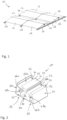
- a photovoltaic mounting system 10 according to the prior art is shown, which is used for arranging PV modules 12 on a flat roof.
- the photovoltaic mounting system 10 here comprises three rows of rails 14, 16, with two rails 14, 16 being arranged in a row one behind the other and connected by means of a connecting element 18.
- the PV modules 12 are arranged between two rails 14 or 16. Overall, this results in a checkerboard-like pattern.
- the connecting element 18 has a base body 20, which is designed here as a hollow body with a cavity 22.
- the base body 20 has a bottom 24, a top 26, a front 28, a back 30 and two open side surfaces 32, 34. In a side view, the base body 20 has a trapezoidal geometry.
- the base body 20 has a first connection section 36 for arrangement in a first rail 14 and a second connection section 38 for arrangement in a second rail 16 (cf. Fig. 3 to 7 ).
- An intermediate section 40 is formed between the first connection section 36 and the second connection section 38.
- the underside 42 of the first connection section 36 and the underside 44 of the second connection section 38 are each convexly curved, so that overall a wave-shaped course of the underside 24 of the base body 20 results.
- the upper side 26 of the base body 20 runs obliquely to the lower side 24, so that the base body 20 has a lower height in the second connection section 38 than in the first connection section 36.
- a longitudinal strut 46a, 46b extends through the cavity 22.
- the longitudinal struts 46a, 46b each extend from the underside 24 to the top side 26.
- the longitudinal struts 46a, 46b each surround an opening 48a, 48b for the passage of a fixing means (cf. Fig. 3 to 6 ).
- the openings 48a, 48b are only partially surrounded by the respective longitudinal strut 46a, 46b.
- a rail structure 50a, 50b is formed on the upper side 26 of the respective connection sections 36, 38.
- the rail structure 50a, 50b is formed here by angled ribs 52.
- the rail structures 50a, 50b are each formed in the transverse direction of the base body 20.
- a stop 54 is formed on the upper side 26 of the base body 20 and here on an angled rib 52.
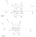
- a photovoltaic mounting system 10 is shown in each case, wherein two rails 14, 16 are arranged one behind the other in a longitudinal direction L, and wherein the two rails 14, 16 are connected to one another by the connecting element 18.
- the two rails 14, 16 are each aligned horizontally and at the same height.
- the connecting element 18 is arranged such that the first connection section 36 extends in the first rail 14, in a gap 56 between two side walls 58, and the second connection section 38 extends analogously in the second rail 16.
- the rails 14, 16 are each fixed to the respective connection section 36, 38 with screws 60 as fixing means 62.
- the screw 60 is arranged so as to protrude through aligned openings in the respective rail and openings 48a, 48b in the corresponding connection section 36, 38.
- the intermediate section 40 is arranged here in the free space 64 between the two rails 14, 16.
- connection sections 36, 38 each rest with their underside 42, 44 on the respective rail 14, 16, whereby the convex curvature results in only a relatively small contact area.
- the respective contact positions are located in the middle, in the extension of the longitudinal strut 46a, 46b and are marked with arrows 66a, 66b.
- Fig.6 the two rails 14, 16 are arranged at an offset height, as can occur when installed on an uneven flat roof.
- the second rail 16 is arranged at a lower height than the first rail 14. Due to the convex underside 24, the first rail 14 and the second rail 16 are now at a height opposite the Fig.3 shown contact positions 66a' and 66b' shifted. The contact positions 66a' and 66b' are shifted here in the direction of the second, lower rail 16.
- FIG.7 another assembly situation is shown, whereby the second rail 16 is inclined downwards relative to the first rail 14.
- the contact positions 66a" and 66b" are shifted relative to the original contact positions 66a and 66b.
- the contact positions 66a" and 66b" in both connection sections 36, 38 are shifted in the direction of the intermediate section 40, relative to the Fig.3 shown initial situation.
Landscapes
- Engineering & Computer Science (AREA)
- Chemical & Material Sciences (AREA)
- Life Sciences & Earth Sciences (AREA)
- Sustainable Development (AREA)
- Sustainable Energy (AREA)
- Thermal Sciences (AREA)
- Physics & Mathematics (AREA)
- Combustion & Propulsion (AREA)
- Mechanical Engineering (AREA)
- General Engineering & Computer Science (AREA)
- Architecture (AREA)
- Civil Engineering (AREA)
- Structural Engineering (AREA)
- Photovoltaic Devices (AREA)
Priority Applications (2)
| Application Number | Priority Date | Filing Date | Title |
|---|---|---|---|
| HRP20260086TT HRP20260086T1 (hr) | 2023-01-27 | 2024-01-15 | Fotonaponski montažni sustav |
| RS20260061A RS67674B1 (sr) | 2023-01-27 | 2024-01-15 | Fotonaponski montažni sistem |
Applications Claiming Priority (1)
| Application Number | Priority Date | Filing Date | Title |
|---|---|---|---|
| DE102023102032.3A DE102023102032B3 (de) | 2023-01-27 | 2023-01-27 | Photovoltaik-Montagesystem |
Publications (3)
| Publication Number | Publication Date |
|---|---|
| EP4407865A1 true EP4407865A1 (fr) | 2024-07-31 |
| EP4407865B1 EP4407865B1 (fr) | 2025-10-22 |
| EP4407865C0 EP4407865C0 (fr) | 2025-10-22 |
Family
ID=89619900
Family Applications (1)
| Application Number | Title | Priority Date | Filing Date |
|---|---|---|---|
| EP24151858.8A Active EP4407865B1 (fr) | 2023-01-27 | 2024-01-15 | Système de montage photovoltaïque |
Country Status (6)
| Country | Link |
|---|---|
| EP (1) | EP4407865B1 (fr) |
| DE (1) | DE102023102032B3 (fr) |
| ES (1) | ES3060035T3 (fr) |
| HR (1) | HRP20260086T1 (fr) |
| PL (1) | PL4407865T3 (fr) |
| RS (1) | RS67674B1 (fr) |
Citations (2)
| Publication number | Priority date | Publication date | Assignee | Title |
|---|---|---|---|---|
| US20120234377A1 (en) * | 2011-03-15 | 2012-09-20 | Richard William Erickson | Unitized photovoltaic assembly |
| US20130111713A1 (en) * | 2011-09-30 | 2013-05-09 | Mainstream Energy Corporation | Wind tunnel optimized solar panel system |
-
2023
- 2023-01-27 DE DE102023102032.3A patent/DE102023102032B3/de active Active
-
2024
- 2024-01-15 PL PL24151858.8T patent/PL4407865T3/pl unknown
- 2024-01-15 EP EP24151858.8A patent/EP4407865B1/fr active Active
- 2024-01-15 HR HRP20260086TT patent/HRP20260086T1/hr unknown
- 2024-01-15 RS RS20260061A patent/RS67674B1/sr unknown
- 2024-01-15 ES ES24151858T patent/ES3060035T3/es active Active
Patent Citations (2)
| Publication number | Priority date | Publication date | Assignee | Title |
|---|---|---|---|---|
| US20120234377A1 (en) * | 2011-03-15 | 2012-09-20 | Richard William Erickson | Unitized photovoltaic assembly |
| US20130111713A1 (en) * | 2011-09-30 | 2013-05-09 | Mainstream Energy Corporation | Wind tunnel optimized solar panel system |
Also Published As
| Publication number | Publication date |
|---|---|
| RS67674B1 (sr) | 2026-02-27 |
| PL4407865T3 (pl) | 2026-04-13 |
| EP4407865B1 (fr) | 2025-10-22 |
| DE102023102032B3 (de) | 2024-03-14 |
| EP4407865C0 (fr) | 2025-10-22 |
| HRP20260086T1 (hr) | 2026-03-13 |
| ES3060035T3 (en) | 2026-03-24 |
Similar Documents
| Publication | Publication Date | Title |
|---|---|---|
| EP2434229B1 (fr) | Crochet de toit pour le montage de modules solaires sur des toits | |
| EP4075077B1 (fr) | Système de fixation de panneaux solaires | |
| EP1123228A1 (fr) | Piece de liaison pour assembler une raclette d'essuie-glace avec un bras d'essuie-glace | |
| EP2904162B1 (fr) | Canal de drainage présentant un corps de canal et un revêtement | |
| DE102005032859B3 (de) | Befestigungssystem für Solarmodule | |
| EP4407865B1 (fr) | Système de montage photovoltaïque | |
| DE102022113986B3 (de) | Befestigung für einen Photovoltaikmodulrahmen und Verfahren zu dessen Befestigung | |
| EP3832051A1 (fr) | Panneau de plancher | |
| CH674392A5 (fr) | ||
| DE202023100435U1 (de) | Dachhaken | |
| AT18252U1 (de) | Tragkonstruktionsmontagesystem für Photovoltaik-Module | |
| DE202022000600U1 (de) | Überdachung | |
| DE102022104203A1 (de) | Doppelbodensystem | |
| DE9215887U1 (de) | Abflußrinne für Flüssigkeiten | |
| CH685782A5 (de) | Schachtrost mit Rahmen. | |
| DE29516040U1 (de) | Tragstütze sowie Tragvorrichtung mit wenigstens vier im Abstand zueinander angeordneten Tragstützen | |
| EP3680414B1 (fr) | Assemblage avec un élément de couverture de toit et deux éléments de fixation séparés | |
| DE102025144822A1 (de) | Anschlag zum Halten eines Gegenstands wie eines Solarmoduls auf einem Träger | |
| DE29902266U1 (de) | Gestell für einen 19"-Verteilerschrank | |
| EP3722529B1 (fr) | Système de toiture | |
| DE102019100981A1 (de) | Einlegeschiene, Adapterschiene und System mit Einlegeschiene und Adapterschiene | |
| EP4459202A1 (fr) | Systeme de lestage | |
| WO2000063505A1 (fr) | Ensemble d'elements de construction servant a former une structure porteuse en treillis | |
| EP4375587A1 (fr) | Système de fixation de module solaire à angles différents | |
| EP4435344A1 (fr) | Système de fixation |
Legal Events
| Date | Code | Title | Description |
|---|---|---|---|
| PUAI | Public reference made under article 153(3) epc to a published international application that has entered the european phase |
Free format text: ORIGINAL CODE: 0009012 |
|
| STAA | Information on the status of an ep patent application or granted ep patent |
Free format text: STATUS: THE APPLICATION HAS BEEN PUBLISHED |
|
| AK | Designated contracting states |
Kind code of ref document: A1 Designated state(s): AL AT BE BG CH CY CZ DE DK EE ES FI FR GB GR HR HU IE IS IT LI LT LU LV MC ME MK MT NL NO PL PT RO RS SE SI SK SM TR |
|
| STAA | Information on the status of an ep patent application or granted ep patent |
Free format text: STATUS: REQUEST FOR EXAMINATION WAS MADE |
|
| 17P | Request for examination filed |
Effective date: 20250130 |
|
| GRAP | Despatch of communication of intention to grant a patent |
Free format text: ORIGINAL CODE: EPIDOSNIGR1 |
|
| STAA | Information on the status of an ep patent application or granted ep patent |
Free format text: STATUS: GRANT OF PATENT IS INTENDED |
|
| RIC1 | Information provided on ipc code assigned before grant |
Ipc: F24S 25/35 20180101ALI20250521BHEP Ipc: F24S 25/33 20180101ALI20250521BHEP Ipc: H02S 30/00 20140101ALI20250521BHEP Ipc: H02S 20/24 20140101AFI20250521BHEP |
|
| INTG | Intention to grant announced |
Effective date: 20250530 |
|
| GRAS | Grant fee paid |
Free format text: ORIGINAL CODE: EPIDOSNIGR3 |
|
| GRAA | (expected) grant |
Free format text: ORIGINAL CODE: 0009210 |
|
| STAA | Information on the status of an ep patent application or granted ep patent |
Free format text: STATUS: THE PATENT HAS BEEN GRANTED |
|
| AK | Designated contracting states |
Kind code of ref document: B1 Designated state(s): AL AT BE BG CH CY CZ DE DK EE ES FI FR GB GR HR HU IE IS IT LI LT LU LV MC ME MK MT NL NO PL PT RO RS SE SI SK SM TR |
|
| REG | Reference to a national code |
Ref country code: CH Ref legal event code: F10 Free format text: ST27 STATUS EVENT CODE: U-0-0-F10-F00 (AS PROVIDED BY THE NATIONAL OFFICE) Effective date: 20251022 Ref country code: GB Ref legal event code: FG4D Free format text: NOT ENGLISH |
|
| RIN1 | Information on inventor provided before grant (corrected) |
Inventor name: BALEN, MARKO Inventor name: HECK, DIETER Inventor name: ROSSBACH, NILS Inventor name: SCHUMACHER, CHRISTIAN Inventor name: SCHWARZ, THOMAS Inventor name: STEUER, SVEN |
|
| REG | Reference to a national code |
Ref country code: DE Ref legal event code: R096 Ref document number: 502024000308 Country of ref document: DE |
|
| REG | Reference to a national code |
Ref country code: IE Ref legal event code: FG4D Free format text: LANGUAGE OF EP DOCUMENT: GERMAN |
|
| U01 | Request for unitary effect filed |
Effective date: 20251120 |
|
| U07 | Unitary effect registered |
Designated state(s): AT BE BG DE DK EE FI FR IT LT LU LV MT NL PT RO SE SI Effective date: 20251127 |
|
| U20 | Renewal fee for the european patent with unitary effect paid |
Year of fee payment: 3 Effective date: 20251124 |
|
| REG | Reference to a national code |
Ref country code: CH Ref legal event code: W10 Free format text: ST27 STATUS EVENT CODE: U-0-0-W10-W00 (AS PROVIDED BY THE NATIONAL OFFICE) Effective date: 20260121 |
|
| REG | Reference to a national code |
Ref country code: CH Ref legal event code: R17 Free format text: ST27 STATUS EVENT CODE: U-0-0-R10-R17 (AS PROVIDED BY THE NATIONAL OFFICE) Effective date: 20260126 |
|
| RAP2 | Party data changed (patent owner data changed or rights of a patent transferred) |
Owner name: RENUSOL EUROPE GMBH |
|
| U1K | Transfer of rights of the unitary patent after the registration of the unitary effect |
Owner name: RENUSOL EUROPE GMBH; DE |
|
| REG | Reference to a national code |
Ref country code: HR Ref legal event code: ODRP Ref document number: P20260086T Country of ref document: HR Payment date: 20260121 Year of fee payment: 3 |
|
| REG | Reference to a national code |
Ref country code: SK Ref legal event code: T3 Ref document number: E 47860 Country of ref document: SK |
|
| REG | Reference to a national code |
Ref country code: HR Ref legal event code: T1PR Ref document number: P20260086 Country of ref document: HR |
|
| REG | Reference to a national code |
Ref country code: ES Ref legal event code: FG2A Ref document number: 3060035 Country of ref document: ES Kind code of ref document: T3 Effective date: 20260324 |
|
| PGFP | Annual fee paid to national office [announced via postgrant information from national office to epo] |
Ref country code: ME Payment date: 20260113 Year of fee payment: 3 |
|
| REG | Reference to a national code |
Ref country code: GB Ref legal event code: 732E Free format text: REGISTERED BETWEEN 20260312 AND 20260318 Ref country code: GR Ref legal event code: EP Ref document number: 20260400126 Country of ref document: GR Effective date: 20260310 |
|
| PGFP | Annual fee paid to national office [announced via postgrant information from national office to epo] |
Ref country code: ES Payment date: 20260204 Year of fee payment: 3 |
|
| PGFP | Annual fee paid to national office [announced via postgrant information from national office to epo] |
Ref country code: NO Payment date: 20260119 Year of fee payment: 3 Ref country code: IE Payment date: 20260122 Year of fee payment: 3 |
|
| PGFP | Annual fee paid to national office [announced via postgrant information from national office to epo] |
Ref country code: HR Payment date: 20260121 Year of fee payment: 3 |
|
| PGFP | Annual fee paid to national office [announced via postgrant information from national office to epo] |
Ref country code: RS Payment date: 20260112 Year of fee payment: 3 |
|
| PG25 | Lapsed in a contracting state [announced via postgrant information from national office to epo] |
Ref country code: IS Free format text: LAPSE BECAUSE OF FAILURE TO SUBMIT A TRANSLATION OF THE DESCRIPTION OR TO PAY THE FEE WITHIN THE PRESCRIBED TIME-LIMIT Effective date: 20260222 |
|
| PGFP | Annual fee paid to national office [announced via postgrant information from national office to epo] |
Ref country code: CZ Payment date: 20260113 Year of fee payment: 3 |
|
| PGFP | Annual fee paid to national office [announced via postgrant information from national office to epo] |
Ref country code: GR Payment date: 20260211 Year of fee payment: 3 Ref country code: PL Payment date: 20260112 Year of fee payment: 3 |
|
| PGFP | Annual fee paid to national office [announced via postgrant information from national office to epo] |
Ref country code: SK Payment date: 20260113 Year of fee payment: 3 |
|
| PGFP | Annual fee paid to national office [announced via postgrant information from national office to epo] |
Ref country code: MK Payment date: 20260226 Year of fee payment: 3 |