EP4407882A1 - Procédé et appareil pour un mesurage de faisceau et un compte-rendu - Google Patents
Procédé et appareil pour un mesurage de faisceau et un compte-rendu Download PDFInfo
- Publication number
- EP4407882A1 EP4407882A1 EP21957762.4A EP21957762A EP4407882A1 EP 4407882 A1 EP4407882 A1 EP 4407882A1 EP 21957762 A EP21957762 A EP 21957762A EP 4407882 A1 EP4407882 A1 EP 4407882A1
- Authority
- EP
- European Patent Office
- Prior art keywords
- resource
- cmr
- different
- remote radio
- reference signal
- Prior art date
- Legal status (The legal status is an assumption and is not a legal conclusion. Google has not performed a legal analysis and makes no representation as to the accuracy of the status listed.)
- Pending
Links
Images


Classifications
-
- H—ELECTRICITY
- H04—ELECTRIC COMMUNICATION TECHNIQUE
- H04B—TRANSMISSION
- H04B7/00—Radio transmission systems, i.e. using radiation field
- H04B7/02—Diversity systems; Multi-antenna system, i.e. transmission or reception using multiple antennas
- H04B7/04—Diversity systems; Multi-antenna system, i.e. transmission or reception using multiple antennas using two or more spaced independent antennas
- H04B7/06—Diversity systems; Multi-antenna system, i.e. transmission or reception using multiple antennas using two or more spaced independent antennas at the transmitting station
- H04B7/0686—Hybrid systems, i.e. switching and simultaneous transmission
- H04B7/0695—Hybrid systems, i.e. switching and simultaneous transmission using beam selection
-
- H—ELECTRICITY
- H04—ELECTRIC COMMUNICATION TECHNIQUE
- H04W—WIRELESS COMMUNICATION NETWORKS
- H04W72/00—Local resource management
- H04W72/04—Wireless resource allocation
-
- H—ELECTRICITY
- H04—ELECTRIC COMMUNICATION TECHNIQUE
- H04B—TRANSMISSION
- H04B7/00—Radio transmission systems, i.e. using radiation field
- H04B7/02—Diversity systems; Multi-antenna system, i.e. transmission or reception using multiple antennas
- H04B7/04—Diversity systems; Multi-antenna system, i.e. transmission or reception using multiple antennas using two or more spaced independent antennas
- H04B7/08—Diversity systems; Multi-antenna system, i.e. transmission or reception using multiple antennas using two or more spaced independent antennas at the receiving station
- H04B7/0868—Hybrid systems, i.e. switching and combining
- H04B7/088—Hybrid systems, i.e. switching and combining using beam selection
-
- H—ELECTRICITY
- H04—ELECTRIC COMMUNICATION TECHNIQUE
- H04L—TRANSMISSION OF DIGITAL INFORMATION, e.g. TELEGRAPHIC COMMUNICATION
- H04L5/00—Arrangements affording multiple use of the transmission path
-
- H—ELECTRICITY
- H04—ELECTRIC COMMUNICATION TECHNIQUE
- H04L—TRANSMISSION OF DIGITAL INFORMATION, e.g. TELEGRAPHIC COMMUNICATION
- H04L5/00—Arrangements affording multiple use of the transmission path
- H04L5/0001—Arrangements for dividing the transmission path
- H04L5/0014—Three-dimensional division
- H04L5/0023—Time-frequency-space
-
- H—ELECTRICITY
- H04—ELECTRIC COMMUNICATION TECHNIQUE
- H04L—TRANSMISSION OF DIGITAL INFORMATION, e.g. TELEGRAPHIC COMMUNICATION
- H04L5/00—Arrangements affording multiple use of the transmission path
- H04L5/003—Arrangements for allocating sub-channels of the transmission path
- H04L5/0048—Allocation of pilot signals, i.e. of signals known to the receiver
-
- H—ELECTRICITY
- H04—ELECTRIC COMMUNICATION TECHNIQUE
- H04L—TRANSMISSION OF DIGITAL INFORMATION, e.g. TELEGRAPHIC COMMUNICATION
- H04L5/00—Arrangements affording multiple use of the transmission path
- H04L5/003—Arrangements for allocating sub-channels of the transmission path
- H04L5/0048—Allocation of pilot signals, i.e. of signals known to the receiver
- H04L5/005—Allocation of pilot signals, i.e. of signals known to the receiver of common pilots, i.e. pilots destined for multiple users or terminals
-
- H—ELECTRICITY
- H04—ELECTRIC COMMUNICATION TECHNIQUE
- H04L—TRANSMISSION OF DIGITAL INFORMATION, e.g. TELEGRAPHIC COMMUNICATION
- H04L5/00—Arrangements affording multiple use of the transmission path
- H04L5/0091—Signalling for the administration of the divided path, e.g. signalling of configuration information
- H04L5/0094—Indication of how sub-channels of the path are allocated
Definitions
- the disclosure relates to the field of communication technology, more particularly, to a method and an apparatus for beam measurement and reporting.
- CMR resource sets are configured for channel measurement resources, with each CMR resource set corresponding to one TRP.
- a network device contains multiple Remote Radio Heads (RRHs)
- the multiple RRHs can simultaneously provide services for the terminal. Therefore, how to perform beam measurement and reporting based on the multiple RRHs is an urgent problem that needs to be solved.
- Embodiments of the disclosure provide a method and an apparatus for beam measurement and reporting, which can be used in the field of communication technology.
- embodiments of the disclosure provide a method for beam measurement and reporting, performed by a terminal.
- the method includes: receiving configuration information, in which the configuration information includes at least two reference signal resources, and the at least two reference signal resources correspond to different remote radio heads respectively.
- the different remote radio heads correspond to at least one of: different transmission and reception points; different control resource set pools; or different antenna panels.
- the method further includes: receiving first indication information, in which the first indication information is used to implement at least one of:
- the method further includes:
- the method further includes: receiving second indication information, in which the second indication information is used to implement at least one of:
- the method further includes: sending a second measurement result report, in which the second measurement result report includes an identifier of at least one resource setting and a measurement result corresponding to each resource setting.
- the measurement result includes an index of a reference signal and a corresponding measurement value
- the reference signal includes a synchronization signal block (SSB) or a channel state information-reference signal (CSI-RS)
- the measurement value includes a layer-1 reference signal reception power (L1-RSRP) or a layer-1 signal to interference noise ratio (L1-SINR).
- different remote radio heads correspond to a same physical cell identifier (PCI), or different remote radio heads correspond to different PCIs.
- PCI physical cell identifier
- inventions of the disclosure provide a method for beam measurement and reporting, performed by a network device.
- the method includes: sending configuration information, in which the configuration information includes at least two reference signal resources, and the at least two reference signal resources correspond to different remote radio heads respectively.
- the different remote radio heads correspond to at least one of: different transmission and reception points; different control resource set pools; or different antenna panels.
- the method further includes: sending first indication information, in which the first indication information is used to implement at least one of:
- the method further includes:
- the method further includes: sending second indication information, in which the second indication information is used to implement at least one of:
- the method further includes: receiving a second measurement result report, in which the second measurement result report includes an identifier of at least one resource setting and a measurement result corresponding to each resource setting.
- the measurement result corresponding to each resource setting includes a plurality of groups, and two reference signals in each group are able to be simultaneously received by the terminal, in which different reference signals in the two reference signals correspond to different remote radio heads; or the measurement result corresponding to each resource setting includes a plurality of groups, and reference signals in different groups are able to be simultaneously received by the terminal.
- the measurement result includes an index of a reference signal and a corresponding measurement value
- the reference signal includes a synchronization signal block (SSB) or a channel state information-reference signal (CSI-RS)
- the measurement value includes a layer-1 reference signal reception power (L1-RSRP) or a layer-1 signal to interference noise ratio (L1-SINR).
- different remote radio heads correspond to a same physical cell identifier (PCI), or different remote radio heads correspond to different PCIs.
- PCI physical cell identifier
- embodiments of the disclosure provide a communication device, performed by a terminal.
- the communication device has an ability to implement part or all of the functions of the terminal in the method described in the first aspect.
- the functions of the communication device may include functions in some or all of the embodiments of the disclosure, or may include a function of independently implementing any embodiment of the disclosure.
- the functions can be implemented by hardware, or can be implemented by executing corresponding software using the hardware.
- the hardware or software includes one or more units or modules corresponding to the above functions.
- embodiments of the disclosure provide a communication device, performed by a network device.
- the communication device has an ability to implement part or all of the functions of the network device in the method described in the second aspect.
- the functions of the communication device may include functions in some or all of the embodiments of the disclosure, or may include a function of independently implementing any embodiment of the disclosure.
- the functions can be implemented by hardware, or can be implemented by executing corresponding software using the hardware.
- the hardware or software includes one or more units or modules corresponding to the above functions.
- inventions of the disclosure provide a communication device.
- the communication device includes: a processor.
- the processor calls a computer program stored in a memory, the method described in the first aspect above is implemented.
- inventions of the disclosure provide a communication device.
- the communication device includes: a processor.
- the processor calls a computer program stored in a memory, the method described in the second aspect above is implemented.
- inventions of the disclosure provide a communication device.
- the communication device includes: a processor and a memory having a computer program stored thereon.
- the computer program is executed by the processor, the communication device is caused to implement the method described in the first aspect above.
- inventions of the disclosure provide a communication device.
- the communication device includes: a processor and a memory having a computer program stored thereon.
- the computer program is executed by the processor, the communication device is caused to implement the method described in the second aspect above.
- inventions of the disclosure provide a communication device.
- the communication device includes: a processor and an interface circuit.
- the interface circuit is configured to receive code instructions and transmit them to the processor.
- the processor is configured to run the code instructions to cause the device to perform the method described in the first aspect above.
- inventions of the disclosure provide a communication device.
- the communication device includes: a processor and an interface circuit.
- the interface circuit is configured to receive code instructions and transmit them to the processor.
- the processor is configured to run the code instructions to cause the device to perform the method described in the second aspect above.
- embodiments of the disclosure provide a communication system.
- the system includes the communication device of the third aspect and the communication device of the fourth aspect; or the system includes the communication device of the fifth aspect and the communication device of the sixth aspect; or the system includes the communication device of the seventh aspect and the communication device of the eighth aspect; or the system includes the communication device of the ninth aspect and the communication device of the tenth aspect.
- embodiments of the disclosure provide a computer-readable storage medium for storing instructions used by the above terminal. When the instructions are executed, the method of the first aspect is implemented.
- embodiments of the disclosure provide a computer-readable storage medium for storing instructions used by the above network device. When the instructions are executed, the method of the second aspect is implemented.
- embodiments of the disclosure provide a computer program product including a computer program.
- the computer program When the computer program is run by a computer, the computer is caused to implement the method of the first aspect.
- embodiments of the disclosure provide a computer program product including a computer program.
- the computer program When the computer program is run by a computer, the computer is caused to implement the method of the second aspect.
- embodiments of the disclosure provide a chip system.
- the chip system includes at least one processor and an interface, to support a terminal in implementing the functions involved in the first aspect, such as determining or processing at least one of the data and information involved in the above method.
- the chip system further includes a memory for storing necessary computer programs and data for the terminal.
- the chip system can be composed of chips or include a chip and other discrete components.
- embodiments of the disclosure provide a chip system.
- the chip system includes at least one processor and an interface, to support a network device in implementing the functions involved in the second aspect, such as determining or processing at least one of the data and information involved in the above method.
- the chip system further includes a memory for storing necessary computer programs and data for the network device.
- the chip system can be composed of chips or include a chip and other discrete components.
- embodiments of the disclosure provide a computer program.
- the computer program runs on a computer, the computer is caused to implement the method of the first aspect.
- embodiments of the disclosure provide a computer program.
- the computer program runs on a computer, the computer is caused to implement the method of the second aspect.
- a baseband optical signal is converted into a radio frequency signal to amplify and transmit. It is also known as a Remote Radio Unit (RRU).
- RRU Remote Radio Unit
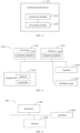
- FIG. 1 is a structural diagram of a communication system provided by an embodiment of the disclosure.
- the communication system may include, but is not limited to, a network device and a terminal.
- the number and form of devices shown in FIG. 1 are only for examples and do not constitute a limitation on the embodiments of the disclosure, and two or more network devices and two or more terminals may be included in practical applications.
- the communication system shown in FIG. 1 may include, for example, a network device 11 and a terminal 12.
- LTE long-term evolution
- 5G fifth generation
- NR 5G new radio
- the network device 11 in embodiments of the disclosure may be an entity on a network side for transmitting or receiving signals.
- the network device 11 may be an evolved NodeB (eNB), a transmission reception point (TRP), a next generation NodeB (gNB) in a new radio (NR) system, a base station in other future mobile communication systems or an access node in a wireless fidelity (Wi-Fi) system.
- eNB evolved NodeB
- TRP transmission reception point
- gNB next generation NodeB
- NR new radio
- Wi-Fi wireless fidelity
- the specific technology and specific device form used by the network device are not limited in the embodiments of the disclosure.
- the network device provided in embodiments of the disclosure may be composed of a central unit (CU) and distributed units (DUs).
- the CU can also be referred to as a control unit.
- a protocol layer of the network device such as a base station
- some protocol layer functions placed in the CU for centralized control, and part of or all the remaining protocol layer functions distributed in the DUs, DUs are centrally controlled by the CU.
- the terminal 12 in embodiments of the disclosure is an entity on a user side for receiving or transmitting signals, such as a cellular phone.
- the terminal may also be referred to as a terminal device, user equipment (UE), a mobile station (MS), a mobile terminal (MT), and the like.
- the terminal may be a vehicle with a communication function, a smart car, a mobile phone, a wearable device, a Pad, a computer with a wireless transceiver function, a virtual reality (VR) terminal, an augmented reality (AR) terminal, a wireless terminal in industrial control, a wireless terminal in self-driving, a wireless terminal in remote medical surgery, a wireless terminal in smart grid, a wireless terminal in transportation safety, a wireless terminal in smart city, a wireless terminal in smart home, etc.
- the specific technology and specific device form adopted by the terminal are not limited in embodiments of the disclosure.
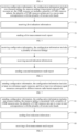
- FIG. 2 is a flowchart of a method for beam measurement and reporting according to an embodiment of the disclosure.
- the method is performed by a terminal.
- the method includes, but is not limited to, the following steps.
- Step 21 configuration information is received, the configuration information includes at least two reference signal resources, and the at least two reference signal resources correspond to different remote radio heads respectively.
- the network device may configure different reference signal resources for the multiple RRHs.
- each RRH has a corresponding reference signal resource.
- beam measurement and reporting may be performed based on the reference signal resource corresponding to each RRH.
- different RRHs may correspond to at least one of: different transmission reception points (TRPs), different control resource set pools (CORESET Pool Indexes), or different antenna panels. That is to say, in embodiments of the disclosure, a RRH may be interchanged with a TRP, a CORESET Pool Index, or an antenna panel.
- different RRHs may correspond to the same Physical Cell Identifier (PCI), or different RRHs may correspond to different PCIs, which is not limited by the disclosure.
- PCI Physical Cell Identifier
- the terminal receives the configuration information, the configuration information includes at least two reference signal resources, and the at least two reference signal resources correspond to different RRHs.
- the terminal can perform beam measurement and reporting based on the reference signal resource configured by the network device for each RRH, which not only ensures a coverage range of signals but also improves a utilization rate of the RRH.
- FIG. 3 is a flowchart of a method for beam measurement and reporting according to an embodiment of the disclosure.
- the method is performed by a terminal.
- the method includes, but is not limited to, the following steps.
- Step 31 configuration information is received, the configuration information includes one resource setting, the resource setting may be associated with a plurality of channel measurement resource (CMR) resource sets, and the plurality of CMR resource sets are in a one-to-one correspondence with the plurality of remote radio heads.
- CMR channel measurement resource
- each RRH corresponds to at least one reference signal resource.
- the plurality of CMR resource sets include two or more CMR resource sets.
- each reference signal resource in the configuration information is included in one CMR resource set, and different reference signal resources may be included in the same CMR resource set or in different CMR resource sets.
- the configuration information includes a resource setting # 1, which is associated with CMR resource set 1, CMR resource set 2, and CMR resource set 3.
- the CMR resource set 1 corresponds to RRH 1
- the CMR resource set 2 corresponds to RRH 2
- the CMR resource set 3 corresponds to RRH 3.
- At least one reference signal resource corresponding to RRH 1 may be included in the CMR resource set 1
- at least one reference signal resource corresponding to RRH 2 may be included in the CMR resource set 2
- at least one reference signal resource corresponding to RRH 3 may be included in the CMR resource set 3, respectively. That is to say, the CMR resource set 1 includes at least one reference signal resource, and all reference signal resources included in the CMR resource set 1 correspond to the RRH 1.
- the CMR resource set 2 includes at least one reference signal resource, and all reference signal resources included in the CMR resource set 2 correspond to the RRH 2.
- the CMR resource set 3 includes at least one reference signal resource, and all reference signal resources included in the CMR resource set correspond to the RRH 3.
- Step 32 first indication information is received.
- the first indication information may be used to implement least one of:
- M is a value less than or equal to the CMR resource set configured in the configuration information.
- the first indication information may be Medium Access Control (MAC) Control Element (CE) information sent by a network device.
- the terminal may determine whether to activate or deactivate the M CMR resource sets according to the MAC CE information.
- MAC Medium Access Control
- CE Control Element
- the network device may activate or deactivate the M CMR resource sets through MAC CE, or through activating or activating a reportconfig (report configuration) associated with the M CMR resource sets.
- a reportconfig report configuration
- the first indication information may be downlink control information (DCI) sent by the network device.
- the terminal may determine, based on the DCI, to perform measurement and reporting based on the M CMR resource sets.
- DCI downlink control information
- the network device may indicate to perform the measurement reporting based on the M CMR resource sets through the DCI, or it can be achieved by indicating a reportconfig associated with the M CMR resource sets.
- the terminal may perform beam measurement for the RRHs.
- Step 33 a first measurement result report is sent.
- the first measurement result report may include multiple groups, N reference signals (RSs) in each group are RSs that the terminal can receive simultaneously.
- RSs reference signals
- N is a positive integer greater than or equal to 2, and different RSs in the N RSs correspond to different RRHs.
- the N RSs may correspond to two or more different RRHs, such as three, four, etc., which is not limited in the disclosure.
- the first measurement result report may include multiple groups, and RSs in different groups are RSs that the terminal can receive simultaneously.
- RRHs there are four RRHs, namely RRH 1, RRH 2, RRH 3, and RRH 4.
- Two RSs obtained from any two groups, such as Group 1 and Group 2 may correspond to RRH 1 and RRH 2 respectively, or RRH 1 and RRH 3 respectively, or RRH 1 and RRH 4 respectively, or RRH 2 and RRH 3 respectively, or RRH 2 and RRH 4 respectively, or RRH 3 and RRH 4 respectively, which is not limited in the disclosure.
- the first measurement result report may include a RS index and a corresponding measurement value.
- the RS includes a Synchronization Signal Block (SSB) or a Channel State Information Reference Signal (CSI-RS).
- the measurement value includes a layer-1 Reference Signal Receiving Power (L1-RSRP) or a layer-1 Signal to Interference Plus Noise Ratio (L1-SINR).
- the terminal may first receive the configuration information, then determine the CMR resource set corresponding to each RRH according to one resource setting associated with multiple CMR resource sets in the configuration information. Then, beam measurement is determined to be performed based on M CMR resource sets based on the received first indication information, and finally the first measurement result report is sent to the network device. In this way, the beam measurement and reporting for multiple RRHs are realized, which not only ensures a coverage range of signals, but also improves a utilization rate of the RRH.
- FIG. 4 is a flowchart of a method for beam measurement and reporting according to an embodiment of the disclosure. The method is performed by a terminal. As shown in FIG. 4 , the method includes, but is not limited to, the following steps.
- Step 41 configuration information is received, the configuration information includes multiple resource settings, each resource setting is associated with one CMR resource set, and the multiple resource settings are in a one-to-one correspondence with multiple RRHs.
- the reference signal resources corresponding to different RRHs are included in CMR resource sets associated with different resource settings in the multiple resource settings, and the reference signal resources corresponding to the same RRH are included in the same CMR resource set.
- Each RRH corresponds to at least one reference signal resource.
- multiple resource settings may include two or more resource settings.
- each reference signal resource in the configuration information is included in one CMR resource set, and different reference signal resources are included in the same CMR resource set or in different CMR resource sets.
- the configuration information includes multiple resource settings, namely resource setting # 1, resource setting # 2, and resource setting # 3.
- the resource setting # 1 is associated with CMR resource set 1
- the resource setting # 2 is associated with CMR resource set 2
- the resource setting # 3 is associated with CMR resource set 3.
- the resource setting # 1 corresponds to RRH 1
- the resource setting # 2 corresponds to RRH 2
- the resource setting # 3 corresponds to RRH 3.
- At least one reference signal resource corresponding to RRH 1 may be included in the CMR resource set 1
- at least one reference signal resource corresponding to RRH 2 may be included in CMR resource set 2
- at least one reference signal resource corresponding to RRH 3 may be included in CMR resource set 3, respectively.
- the CMR resource set 1 includes at least one reference signal resource, and all reference signal resources included in the CMR resource set 1 correspond to the RRH 1;
- the CMR resource set 2 includes at least one reference signal resource, and all reference signal resources included in the CMR resource set 2 correspond to the RRH 2;
- the CMR resource set 3 includes at least one reference signal resource, and all reference signal resources included in the CMR resource set 3 correspond to the RRH 3.
- Step 42 first indication information is received.
- the first indication information is used to implement at least one of:
- M is a value less than or equal to the resource setting included in the configuration information.
- the first indication information may be MAC CE information sent by a network device.
- the terminal may determine to activate or deactivate the M resource settings according to the MAC CE information.
- the network device may activate or deactivate the M resource settings through MAC CE, or through activating or activating a reportconfig (report configuration) associated with the M resource settings.
- a reportconfig report configuration
- the first indication information may be DCI sent by the network device.
- the terminal may determine, according to the DCI, to perform measurement and reporting based on the M resource settings.
- the network devices indicates to perform the measurement based on the M resource settings through DCI, or by indicating a reportconfig associated with the M resource settings.
- the terminal may perform a beam measurement for the RRHs.
- Step 43 a first measurement result report is sent.
- the first measurement result report may include multiple groups, and N reference signals (RSs) in each group are RSs that the terminal can receive simultaneously.
- RSs reference signals
- N is a positive integer greater than or equal to 2, and different RSs in the N RSs correspond to different RRHs.
- the N RSs may correspond to two or more different RRHs, such as three, four, etc., which is not limited in the disclosure.
- the first measurement result report may include multiple groups, and the RSs in different groups are RSs that the terminal can receive simultaneously.
- RRHs there are four RRHs, namely RRH 1, RRH 2, RRH 3, and RRH 4.
- Two RSs obtained from any two groups, such as Group 1 and Group 2 may correspond to RRH 1 and RRH 2 respectively, or RRH 1 and RRH 3 respectively, or RRH 1 and RRH 4 respectively, or RRH 2 and RRH 3 respectively, or RRH 2 and RRH 4 respectively, or RRH3 and RRH4 respectively, which is not limited in the disclosure.
- the first measurement result report may include a RS index and a corresponding measurement value.
- the RS includes a SSB or a CSI-RS, and the measurement value includes a L1 -RSRP or a L1 -SINR.
- the terminal may first receive the configuration information, then determine the resource setting corresponding to each RRH according to each resource setting associated with the CMR resource set in the configuration information, and then determine to perform the beam measurement based on the M resource settings based on the received first indication information. Finally, the terminal sends the first measurement result report to the network device. In this way, the beam measurement and reporting for multiple RRHs are realized, which not only ensures a coverage range of signals, but also improves a utilization rate of the RRHs.
- FIG. 5 is a flowchart of a method for beam measurement and reporting according to an embodiment of the disclosure. The method is performed by a terminal. As shown in FIG. 5 , the method includes, but is not limited to, the following steps.
- Step 51 configuration information is received, the configuration information includes one resource setting, the resource setting is associated with one CMR resource set, the CMR resource set includes multiple CMR resource subsets, and multiple CMR resource subsets are in a one-to-one correspondence with multiple RRHs.
- Reference signal resources corresponding to different RRHs are included in different CMR resource subsets of the multiple CMR resource subsets. Reference signal resources corresponding to the same RRH are included in the same CMR resource subset. Each RRH corresponds to at least one reference signal resource.
- multiple CMR resource subsets include two or more CMR resource subsets.
- each reference signal resource in the configuration information is included in one CMR resource subset, and different reference signal resources are included in the same CMR resource subset or in different CMR resource subsets.
- the configuration information includes one resource setting that is associated with one CMR resource set.
- the CMR resource set includes CMR resource subset 1, CMR resource subset 2, and CMR resource subset 3.
- the CMR resource subset 1 corresponds to RRH 1
- the CMR resource subset 2 corresponds to RRH 2
- the CMR resource subset 3 corresponds to RRH 3.
- At least one reference signal resource corresponding to RRH 1 may be included in the CMR resource subset 1
- at least one reference signal resource corresponding to RRH 2 may be included in the CMR resource subset 2
- at least one reference signal resource corresponding to RRH 3 may be included in the CMR resource subset 3, respectively.
- the CMR resource subset 1 includes at least one reference signal resource, and all reference signal resources included in the CMR resource subset 1 correspond to RRH 1;
- the CMR resource subset 2 includes at least one reference signal resource, and all reference signal resources included in the CMR resource subset 2 correspond to RRH 2;
- the CMR resource subset 3 includes at least one reference signal resource, and all reference signal resources included in the CMR resource subset 3 correspond to RRH 3.
- Step 52 first indication information is received.
- the first indication information is used to implement at least one of:
- M is a value less than or equal to the CMR resource subset included in the configuration information.
- the first indication information may be MAC CE information sent by a network device.
- the terminal may determine whether to activate or deactivate the M CMR resource subsets according to the MAC CE information.
- the network device may activate or deactivate the M resource subsets through the MAC CE, or through activating or deactivating a reportconfig (report configuration) associated with the M resource subsets.
- a reportconfig report configuration
- the first indication information can also be a DCI sent by the network device.
- the terminal may determine, based on the DCI, to perform the measurement and reporting based on the M CMR resource subsets.
- the network device may indicate to perform the measurement based on the M resource subsets through the DCI, or by indicating a reportconfig associated with the M resource subsets.
- the terminal may perform the beam measurement for the RRHs.
- Step 53 a first measurement result report is sent.
- step 53 may refer to the detailed description in other embodiments of the disclosure, and will not be elaborated here.
- the terminal may first receive the configuration information, then determine the CMR resource subset corresponding to each RRH based on the one resource setting associated with the multiple CMR resource subsets in the configuration information, and then determine to perform the beam measurement based on M CMR resource subsets according to the received first indication information. Finally, the terminal sends the first measurement result report to the network device. In this way, the beam measurement and reporting for multiple RRHs are realized, which not only ensures a coverage range of the signals, but also improves a utilization rate of the RRHs.
- FIG. 6 is a flowchart of a method for beam measurement and reporting according to an embodiment of the disclosure. The method is performed by a terminal. As shown in FIG. 6 , the method includes, but is not limited to, the following steps.
- Step 61 configuration information is received, and the configuration information includes multiple resource settings.
- each resource setting may include two CMR resource sets.
- the two CMR resource sets are in a one-to-one correspondence with two RRHs.
- At least one reference signal resource corresponding to a first RRH of the two RRHs is included in a first one of the two different CMR resource sets, and at least one reference signal resource corresponding to a second RRH of the two RRHs is included in a second one of the two different CMR resource sets, respectively.
- resource setting # 1 includes two CMR resource sets, namely, CMR resource set 1 and CMR resource set 2.
- the CMR resource set1 corresponds to RRH 1
- the CMR resource set 2 corresponds to RRH 2.
- At least one reference signal resource corresponding to RRH 1 may be included in the CMR resource set 1
- at least one reference signal resource corresponding to RRH 2 may be included in the CMR resource set 2, respectively.
- the CMR resource set 1 includes at least one reference signal resource, and all reference signal resources included in the CMR resource set 1 correspond to RRH 1
- the CMR resource set 2 includes at least one reference signal resource, and all reference signal resources included in the CMR resource set 2 correspond to RRH 2.
- the network device may configure three resource settings, where resource setting 1 corresponds to the CMR resource sets of RRH 1 and RRH 2, resource setting 2 corresponds to the CMR resource sets of RRH 1 and RRH 3, and resource setting 3 corresponds to the CMR resource set of RRH 2 and RRH3.
- each resource setting may include one CMR resource set, which includes two CMR resource subsets that are in a one-to-one correspondence with two RRHs. At least one reference signal resource corresponding to a first RRH of the different RRHs is included in a first one of the two different CMR resource subsets, and at least one reference signal resource corresponding to a second RRH of the different RRHs is included in a second one of the two different CMR resource subsets.
- resource setting 1 includes one CMR resource set, which includes CMR resource subset 1 and CMR resource subset 2.
- the CMR resource subset 1 corresponds to RRH 1
- the CMR resource subset 2 corresponds to RRH 2.
- At least one reference signal resource corresponding to RRH 1 may be included in the CMR resource subset 1
- at least one reference signal resource corresponding to RRH 2 may be included in the CMR resource subset 2, respectively. That is to say, the CMR resource subset 1 includes at least one reference signal resource, and all reference signal resources included in the CMR resource subset 1 correspond to RRH 1;
- the CMR resource subset 2 includes at least one reference signal resource, and all reference signal resources included in the CMR resource subset 2 correspond to RRH 2.
- the network device may configure three resource settings, where resource setting 1 corresponds to the CMR resource subsets of RRH 1 and RRH 2; resource setting 2 corresponds to the CMR resource subsets of RRH 1 and RRH 3; resource setting 3 corresponds to the CMR resource subsets of RRH 2 and RRH 3.
- Step 62 second indication information is received.
- the second indication information is used to implement at least one of:
- the second indication information may be MAC CE information sent by the network device.
- the terminal may determine whether to activate or deactivate the resource associated with any resource setting based on the MAC CE information.
- the network device may activate or deactivate the resource associated with any resource setting through the MAC CE, or through activating or deactivating a reportconfig (report configuration) associated with the resource setting.
- a reportconfig report configuration
- the second indication information may be a DCI sent by the network device.
- the terminal may determine the resource associated with any resource setting based on the DCI.
- the network devices may indicate to perform a measurement based on the resource associated with any resource setting through the DCI, or by indicating a reportconfig associated with the resource setting.
- the terminal may perform the beam measurement for the RRHs.
- Step 63 a second measurement result report is sent, and the second measurement result report includes an identifier of at least one resource setting and a measurement result corresponding each resource setting.
- the measurement result may include a RS index and a corresponding measurement value.
- the RS includes a SSB or a CSI-RS.
- the measurement value includes a L1-RSRP or a L1-SINR.
- the measurement result corresponding to each resource setting may include multiple groups, and the two RSs in each group are RSs that the terminal can receive simultaneously. Different RSs in the two RSs correspond to different RRHs.
- two CMR resource sets are in a one-to-one correspondence with two RRHs or two CMR resource subsets are in a one-to-one correspondence with two RRHs
- two RRHs corresponding to each resource setting are fixed, and the measurement result corresponding to the resource setting reported by the terminal may include the RSs and measurement results of the two RRHs.
- Resource setting 1 corresponds to the CMR resource sets or CMR resource subsets of RRH 1 and RRH 2
- resource setting2 corresponds to the CMR resource sets or CMR resource subsets of RRH 1 and RRH 3
- resource setting 3 corresponds to the CMR resource sets or CMR resource subsets of RRH 2 and RRH 3.
- a measurement result for resource setting 1 is measurement results for RRH 1 and RRH 2.
- a measurement result for resource setting 2 is measurement results for RRH 1 and RRH 3.
- a measurement result for resource setting 3 is measurement results for RRH 2 and RRH 3.
- the measurement result corresponding to each resource setting may include multiple groups, and RSs in different groups are RSs that the terminal can receive simultaneously.
- two CMR resource sets are in a one-to-one correspondence with two RRHs, or two CMR resource subsets are in a one-to-one correspondence with two RRHs
- two RRHs corresponding to each resource setting are fixed, and the measurement results corresponding to the resource settings reported by the terminal may include the RSs and measurement results of the two RRHs.
- Resource setting 1 corresponds to the CMR resource sets or CMR resource subsets of RRH1 and RRH2
- resource setting 2 corresponds to the CMR resource sets or CMR resource subsets of RRH 1 and RRH 3
- resource setting 3 corresponds to the CMR resource sets or CMR resource subsets of RRH 1 and RRH 3.
- a measurement result for resource settingl is the measurement results for RRH 1 and RRH 2
- a measurement results for resource setting 2 is the measurement results for RRH 1 and RRH 3
- a the measurement result for resource setting 3 is the measurement results for RRH 2 and RRH 3.
- the terminal may first receive the configuration information, then determine the CMR resource set or CMR resource subset corresponding to each RRH based on the multiple resource settings included in the configuration information, and then determine an available resource setting based on the received second indication information. After perform the beam measurement, the second measurement result report may be sent to the network device. In this way, the beam measurement and reporting for multiple RRHs are realized, which not only ensures a coverage range of signals, but also improves a utilization rate of the RRHs.
- FIG. 7 is a flowchart of a method for beam measurement and reporting according to an embodiment of the disclosure.
- the method is performed by a network device.
- the method includes, but is not limited to, the following steps.
- Step 71 configuration information is sent, the configuration information includes at least two reference signal resources, and the at least two reference signal resources correspond to different RRHs.
- the network device may configure different reference signal resources for the multiple RRHs.
- each RRH has a corresponding reference signal resource.
- beam measurement and reporting may be performed based on the reference signal resource corresponding to each RRH.
- different RRHs may correspond to at least one of: different transmission reception points (TRPs), different control resource set pools (CORESET Pool Indexes), or different antenna panels. That is to say, in embodiments of the disclosure, a RRH may be interchanged with a TRP, a CORESET Pool Index, or an antenna panel.
- different RRHs may correspond to the same Physical Cell Identifier (PCI), or different RRHs may correspond to different PCIs, which is not limited by the disclosure.
- PCI Physical Cell Identifier
- the network device sends the configuration information, the configuration information includes at least two reference signal resources, and the at least two reference signal resources correspond to different RRHs.
- the terminal can perform beam measurement and reporting based on the reference signal resource configured by the network device for each RRH, which not only ensures a coverage range of signals but also improves a utilization rate of the RRH.
- FIG. 8 is a flowchart of a method for beam measurement and reporting according to an embodiment of the disclosure.
- the method is performed by a network device.
- the method includes, but is not limited to, the following steps.
- Step 81 configuration information is sent, the configuration information includes one resource setting, the resource setting may be associated with a plurality of channel measurement resource (CMR) resource sets, and the plurality of CMR resource sets are in a one-to-one correspondence with the plurality of remote radio heads.
- CMR channel measurement resource
- each RRH corresponds to at least one reference signal resource.
- the plurality of CMR resource sets include two or more CMR resource sets.
- each reference signal resource in the configuration information is included in one CMR resource set, and different reference signal resources may be included in the same CMR resource set or in different CMR resource sets.
- the configuration information includes a resource setting # 1, which is associated with CMR resource set 1, CMR resource set 2, and CMR resource set 3.
- the CMR resource set 1 corresponds to RRH 1
- the CMR resource set 2 corresponds to RRH 2
- the CMR resource set 3 corresponds to RRH 3.
- At least one reference signal resource corresponding to RRH 1 may be included in the CMR resource set 1
- at least one reference signal resource corresponding to RRH 2 may be included in the CMR resource set 2
- at least one reference signal resource corresponding to RRH 3 may be included in the CMR resource set 3, respectively. That is to say, the CMR resource set 1 includes at least one reference signal resource, and all reference signal resources included in the CMR resource set 1 correspond to the RRH 1.
- the CMR resource set 2 includes at least one reference signal resource, and all reference signal resources included in the CMR resource set 2 correspond to the RRH 2.
- the CMR resource set 3 includes at least one reference signal resource, and all reference signal resources included in the CMR resource set correspond to the RRH 3.
- Step 82 first indication information is sent.
- the first indication information may be used to implement least one of:
- M is a value less than or equal to the CMR resource set configured in the configuration information.
- the first indication information may be Medium Access Control (MAC) Control Element (CE) information sent by a network device.
- MAC Medium Access Control
- CE Control Element
- DCI downlink control information
- the network device may activate or deactivate the M CMR resource sets through MAC CE, or through activating or activating a reportconfig (report configuration) associated with the M CMR resource sets.
- a reportconfig report configuration
- the network device may indicate to perform the measurement reporting based on the M CMR resource sets through the DCI, or it can be achieved by indicating a reportconfig associated with the M CMR resource sets.
- the terminal may perform beam measurement and reporting based on the M CMR resource sets.
- Step 83 a first measurement result report is received.
- the first measurement result report may include multiple groups, N reference signals (RSs) in each group are RSs that the terminal can receive simultaneously.
- RSs reference signals
- N is a positive integer greater than or equal to 2, and different RSs in the N RSs correspond to different RRHs.
- the N RSs may correspond to two or more different RRHs, such as three, four, etc., which is not limited in the disclosure.
- the first measurement result report may include multiple groups, and RSs in different groups are RSs that the terminal can receive simultaneously.
- RRHs there are four RRHs, namely RRH 1, RRH 2, RRH 3, and RRH 4.
- Two RSs obtained from any two groups, such as Group 1 and Group 2 may correspond to RRH 1 and RRH 2 respectively, or RRH 1 and RRH 3 respectively, or RRH 1 and RRH 4 respectively, or RRH 2 and RRH 3 respectively, or RRH 2 and RRH 4 respectively, or RRH 3 and RRH 4 respectively, which is not limited in the disclosure.
- the first measurement result report may include a RS index and a corresponding measurement value.
- the RS includes a Synchronization Signal Block (SSB) or a Channel State Information Reference Signal (CSI-RS).
- the measurement value includes a layer-1 Reference Signal Receiving Power (L1-RSRP) or a layer-1 Signal to Interference Plus Noise Ratio (L1-SINR).
- the network device may first send the configuration information to the terminal, so that the terminal can determine the CMR resource set corresponding to each RRH according to one resource setting associated with multiple CMR resource sets in the configuration information. Then, the first indication information is sent to the terminal, so that the terminal can perform beam measurement based on the CMR resource sets, and finally the first measurement result report sent by the terminal is received. In this way, the beam measurement and reporting for multiple RRHs are realized, which not only ensures a coverage range of signals, but also improves a utilization rate of the RRH.
- FIG. 9 is a flowchart of a method for beam measurement and reporting according to an embodiment of the disclosure.
- the method is performed by a network device.
- the method includes, but is not limited to, the following steps.
- Step 91 configuration information is sent, the configuration information includes multiple resource settings, each resource setting is associated with one CMR resource set, and the multiple resource settings are in a one-to-one correspondence with multiple RRHs.
- the reference signal resources corresponding to different RRHs are included in CMR resource sets associated with different resource settings in the multiple resource settings, and the reference signal resources corresponding to the same RRH are included in the same CMR resource set.
- Each RRH corresponds to at least one reference signal resource.
- multiple resource settings may include two or more resource settings.
- each reference signal resource in the configuration information is included in one CMR resource set, and different reference signal resources are included in the same CMR resource set or in different CMR resource sets.
- the configuration information includes multiple resource settings, namely resource setting # 1, resource setting # 2, and resource setting # 3.
- the resource setting # 1 is associated with CMR resource set 1
- the resource setting # 2 is associated with CMR resource set 2
- the resource setting # 3 is associated with CMR resource set 3.
- the resource setting # 1 corresponds to RRH 1
- the resource setting # 2 corresponds to RRH 2
- the resource setting # 3 corresponds to RRH 3.
- At least one reference signal resource corresponding to RRH 1 may be included in the CMR resource set 1
- at least one reference signal resource corresponding to RRH 2 may be included in CMR resource set 2
- at least one reference signal resource corresponding to RRH 3 may be included in CMR resource set 3, respectively.
- the CMR resource set 1 includes at least one reference signal resource, and all reference signal resources included in the CMR resource set 1 correspond to the RRH 1;
- the CMR resource set 2 includes at least one reference signal resource, and all reference signal resources included in the CMR resource set 2 correspond to the RRH 2;
- the CMR resource set 3 includes at least one reference signal resource, and all reference signal resources included in the CMR resource set 3 correspond to the RRH 3.
- Step 92 first indication information is sent.
- the first indication information is used to implement at least one of:
- M is a value less than or equal to the resource setting included in the configuration information.
- the first indication information may be MAC CE information sent by the network device.
- the first indication information may be DCI sent by the network device.
- the network device may activate or deactivate the M resource settings through MAC CE, or through activating or activating a reportconfig (report configuration) associated with the M resource settings.
- a reportconfig report configuration
- the network device may indicate to perform measurement based on the M resource settings, through the DCI, or by indicating a reportconfig associated with the M resource settings.
- the terminal can determine an available resource setting and then can perform a beam measurement for the RRHs.
- Step 93 a first measurement result report is received.
- the first measurement result report may include multiple groups, and N reference signals (RSs) in each group are RSs that the terminal can receive simultaneously.
- RSs reference signals
- N is a positive integer greater than or equal to 2, and different RSs in the N RSs correspond to different RRHs.
- the N RSs may correspond to two or more different RRHs, such as three, four, etc., which is not limited in the disclosure.
- the first measurement result report may include multiple groups, and the RSs in different groups are RSs that the terminal can receive simultaneously.
- RRHs there are four RRHs, namely RRH 1, RRH 2, RRH 3, and RRH 4.
- Two RSs obtained from any two groups, such as Group 1 and Group 2 may correspond to RRH 1 and RRH 2 respectively, or RRH 1 and RRH 3 respectively, or RRH 1 and RRH 4 respectively, or RRH 2 and RRH 3 respectively, or RRH 2 and RRH 4 respectively, or RRH3 and RRH4 respectively, which is not limited in the disclosure.
- the first measurement result report may include a RS index and a corresponding measurement value.
- the RS includes a SSB or a CSI-RS, and the measurement value includes a L1 -RSRP or a L1 -SINR.
- the network device may first send the configuration information, so that the terminal can determine the resource setting corresponding to each RRH according to each resource setting associated with the CMR resource set included in the configuration information, and then the network device sends the first indication information to the terminal, so that the terminal can perform the beam measurement based on the M resource settings. Finally, the network device receives the first measurement result report sent by the terminal. In this way, the beam measurement and reporting for multiple RRHs are realized, which not only ensures a coverage range of signals, but also improves a utilization rate of the RRHs.
- FIG. 10 is a flowchart of a method for beam measurement and reporting according to an embodiment of the disclosure. The method is performed by a terminal. As shown in FIG. 10 , the method includes, but is not limited to, the following steps.
- Step 101 configuration information is sent, the configuration information includes one resource setting, the resource setting is associated with one CMR resource set, the CMR resource set includes multiple CMR resource subsets, and multiple CMR resource subsets are in a one-to-one correspondence with multiple RRHs.
- Reference signal resources corresponding to different RRHs are included in different CMR resource subsets of the multiple CMR resource subsets. Reference signal resources corresponding to the same RRH are included in the same CMR resource subset. Each RRH corresponds to at least one reference signal resource.
- multiple CMR resource subsets include two or more CMR resource subsets.
- each reference signal resource in the configuration information is included in one CMR resource subset, and different reference signal resources are included in the same CMR resource subset or in different CMR resource subsets.
- the configuration information includes one resource setting that is associated with one CMR resource set.
- the CMR resource set includes CMR resource subset 1, CMR resource subset 2, and CMR resource subset 3.
- the CMR resource subset 1 corresponds to RRH 1
- the CMR resource subset 2 corresponds to RRH 2
- the CMR resource subset 3 corresponds to RRH 3.
- At least one reference signal resource corresponding to RRH 1 may be included in the CMR resource subset 1
- at least one reference signal resource corresponding to RRH 2 may be included in the CMR resource subset 2
- at least one reference signal resource corresponding to RRH 3 may be included in the CMR resource subset 3, respectively.
- the CMR resource subset 1 includes at least one reference signal resource, and all reference signal resources included in the CMR resource subset 1 correspond to RRH 1;
- the CMR resource subset 2 includes at least one reference signal resource, and all reference signal resources included in the CMR resource subset 2 correspond to RRH 2;
- the CMR resource subset 3 includes at least one reference signal resource, and all reference signal resources included in the CMR resource subset 3 correspond to RRH 3.
- Step 102 first indication information is sent.
- the first indication information is used to implement at least one of:
- M is a value less than or equal to the CMR resource subset included in the configuration information.
- the first indication information may be MAC CE information sent by the network device.
- the first indication information may be DCI sent by the network device.
- the network device may activate or deactivate the M resource subsets through the MAC CE, or through activating or deactivating a reportconfig (report configuration) associated with the M resource subsets.
- a reportconfig report configuration
- the network device may indicate to perform the measurement based on the M resource subsets through the DCI, or by indicating a reportconfig associated with the M resource subsets.
- the terminal can determine an available CMR resource subset and then perform the beam measurement for the RRHs.
- Step 103 a first measurement result report is received.
- step 103 may refer to the detailed description in other embodiments of the disclosure, and will not be elaborated here.
- the network device can first send the configuration information, so that the terminal can determine the CMR resource subset corresponding to each RRH based on the one resource setting associated with the multiple CMR resource subsets in the configuration information, and the network device then sends the first indication information to the terminal, so that the terminal can perform the beam measurement based on M CMR resource subsets. Finally, the network device receives the first measurement result report sent by the terminal. In this way, the beam measurement and reporting for multiple RRHs are realized, which not only ensures a coverage range of the signals, but also improves a utilization rate of the RRHs.
- FIG. 11 is a flowchart of a method for beam measurement and reporting according to an embodiment of the disclosure. The method is performed by a terminal. As shown in FIG. 11 , the method includes, but is not limited to, the following steps.
- Step 101 configuration information is sent, and the configuration information includes multiple resource settings.
- each resource setting may include two CMR resource sets.
- the two CMR resource sets are in a one-to-one correspondence with two RRHs.
- At least one reference signal resource corresponding to a first RRH of the two RRHs is included in a first one of the two different CMR resource sets, and at least one reference signal resource corresponding to a second RRH of the two RRHs is included in a second one of the two different CMR resource sets, respectively.
- resource setting # 1 includes two CMR resource sets, namely, CMR resource set 1 and CMR resource set 2.
- the CMR resource set1 corresponds to RRH 1
- the CMR resource set 2 corresponds to RRH 2.
- At least one reference signal resource corresponding to RRH 1 may be included in the CMR resource set 1
- at least one reference signal resource corresponding to RRH 2 may be included in the CMR resource set 2, respectively.
- the CMR resource set 1 includes at least one reference signal resource, and all reference signal resources included in the CMR resource set 1 correspond to RRH 1
- the CMR resource set 2 includes at least one reference signal resource, and all reference signal resources included in the CMR resource set 2 correspond to RRH 2.
- the network device may configure three resource settings, where resource setting 1 corresponds to the CMR resource sets of RRH 1 and RRH 2, resource setting 2 corresponds to the CMR resource sets of RRH 1 and RRH 3, and resource setting 3 corresponds to the CMR resource set of RRH 2 and RRH3.
- each resource setting may include one CMR resource set, which includes two CMR resource subsets that are in a one-to-one correspondence with two RRHs. At least one reference signal resource corresponding to a first RRH of the different RRHs is included in a first one of the two different CMR resource subsets, and at least one reference signal resource corresponding to a second RRH of the different RRHs is included in a second one of the two different CMR resource subsets.
- resource setting 1 includes one CMR resource set, which includes CMR resource subset 1 and CMR resource subset 2.
- the CMR resource subset 1 corresponds to RRH 1
- the CMR resource subset 2 corresponds to RRH 2.
- At least one reference signal resource corresponding to RRH 1 may be included in the CMR resource subset 1
- at least one reference signal resource corresponding to RRH 2 may be included in the CMR resource subset 2, respectively. That is to say, the CMR resource subset 1 includes at least one reference signal resource, and all reference signal resources included in the CMR resource subset 1 correspond to RRH 1;
- the CMR resource subset 2 includes at least one reference signal resource, and all reference signal resources included in the CMR resource subset 2 correspond to RRH 2.
- the network device may configure three resource settings, where resource setting 1 corresponds to the CMR resource subsets of RRH 1 and RRH 2; resource setting 2 corresponds to the CMR resource subsets of RRH 1 and RRH 3; resource setting 3 corresponds to the CMR resource subsets of RRH 2 and RRH 3.
- Step 112 second indication information is sent.
- the second indication information is used to implement at least one of:
- the second indication information may be MAC CE information sent by the network device.
- the second indication information may be DCI sent by the network device.
- the network device may activate or deactivate the resource associated with any resource setting through the MAC CE, or through activating or deactivating a reportconfig (report configuration) associated with the resource setting.
- a reportconfig report configuration
- the network devices may indicate to perform a measurement based on the resource associated with any resource setting through the DCI, or by indicating a reportconfig associated with the resource setting.
- the terminal may determine an available resource setting and then performs the beam measurement for the RRHs.
- Step 113 a second measurement result report is received, and the second measurement result report includes an identifier of at least one resource setting and a measurement result corresponding each resource setting.
- the measurement result may include a RS index and a corresponding measurement value.
- the RS includes a SSB or a CSI-RS.
- the measurement value includes a L1-RSRP or a L1-SINR.
- the measurement result corresponding to each resource setting may include multiple groups, and the two RSs in each group are RSs that the terminal can receive simultaneously. Different RSs in the two RSs correspond to different RRHs.
- two CMR resource sets are in a one-to-one correspondence with two RRHs, or where two CMR resource subsets are in a one-to-one correspondence with two RRHs, two RRHs corresponding to each resource setting are fixed, and the measurement result corresponding to the resource setting reported by the terminal may include the RSs and measurement results of the two RRHs.
- Resource setting 1 corresponds to the CMR resource sets or CMR resource subsets of RRH 1 and RRH 2
- resource setting2 corresponds to the CMR resource sets or CMR resource subsets of RRH 1 and RRH 3
- resource setting 3 corresponds to the CMR resource sets or CMR resource subsets of RRH 2 and RRH 3.
- a measurement result for resource setting 1 is measurement results for RRH 1 and RRH 2.
- a measurement result for resource setting 2 is measurement results for RRH 1 and RRH 3.
- a measurement result for resource setting 3 is measurement results for RRH 2 and RRH 3.
- the measurement result corresponding to each resource setting may include multiple groups, and RSs in different groups are RSs that the terminal can receive simultaneously.
- two CMR resource sets are in a one-to-one correspondence with two RRHs, or where two CMR resource subsets are in a one-to-one correspondence with two RRHs, two RRHs corresponding to each resource setting are fixed, and the measurement results corresponding to the resource settings reported by the terminal may include the RSs and measurement results of the two RRHs.
- Resource setting 1 corresponds to the CMR resource sets or CMR resource subsets of RRH1 and RRH2
- resource setting 2 corresponds to the CMR resource sets or CMR resource subsets of RRH 1 and RRH 3
- resource setting 3 corresponds to the CMR resource sets or CMR resource subsets of RRH 1 and RRH 3.
- a measurement result for resource settingl is the measurement results for RRH 1 and RRH 2
- a measurement results for resource setting 2 is the measurement results for RRH 1 and RRH 3
- a the measurement result for resource setting 3 is the measurement results for RRH 2 and RRH 3.
- the network device may first send the configuration information to the terminal, so that the terminal can determine the CMR resource set or CMR resource subset corresponding to each RRH based on the multiple resource settings included in the configuration information, and then the network device may send the second indication information to the terminal, so that the terminal can perform the beam measurement based on M CMR resource sets or CMR resource subsets. Finally, the network device receives the second measurement result report sent by the terminal. In this way, the beam measurement and reporting for multiple RRHs are realized, which not only ensures a coverage range of signals, but also improves a utilization rate of the RRHs.
- the methods provided in embodiments of the disclosure are introduced from perspectives of the network device and the terminal.
- the network device and the terminal may include hardware structures and software modules, and may implement the above various functions in the form of hardware structures, software modules, or the hardware structures in combination with the software modules.
- a certain function of the above functions can be executed in the form of a hardware structure, a software module, or a hardware structure in combination with a software module.
- FIG. 12 is a block diagram of a communication device 120 provided by an embodiment of the disclosure.
- the communication device 120 in FIG. 12 includes a processing module 1201 and a transceiver module 1202.
- the transceiver module 1202 may include a sending module and/or a receiving module.
- the sending module is configured to implement a sending function
- the receiving module is configured to implement a receiving function
- the transceiver module 1202 is configured to implement a sending and/or receiving function.
- communication device 120 may be a terminal, a device within the terminal, or a device that can be matched and used with the terminal.
- the communication device 120 at the terminal side, includes: a transceiver module 1202, configured to receive configuration information, in which the configuration information includes at least two reference signal resources, and the at least two reference signal resources correspond to different remote radio heads respectively.
- the different remote radio heads correspond to at least one of: different transmission and reception points; different control resource set pools; or different antenna panels.
- the transceiver module 1202 is configured to: receive first indication information, in which the first indication information is used to implement at least one of:
- the transceiver module 1202 is configured to::
- the transceiver module 1202 is configured to:
- the transceiver module 1202 is configured to: send a second measurement result report, in which the second measurement result report includes an identifier of at least one resource setting and a measurement result corresponding to each resource setting.
- the measurement result includes an index of a reference signal and a corresponding measurement value
- the reference signal includes a synchronization signal block (SSB) or a channel state information-reference signal (CSI-RS)
- the measurement value includes a layer-1 reference signal reception power (L1-RSRP) or a layer-1 signal to interference noise ratio (L1-SINR).
- different remote radio heads correspond to a same physical cell identifier (PCI), or different remote radio heads correspond to different PCIs.
- PCI physical cell identifier
- the terminal receives the configuration information, the configuration information includes at least two reference signal resources, and the at least two reference signal resources correspond to different RRHs.
- the terminal can perform beam measurement and reporting based on the reference signal resource configured by the network device for each RRH, which not only ensures a coverage range of signals but also improves a utilization rate of the RRH.
- communication device 120 may be a network device, a device within the network device, or a device that can be matched and used with the network device.
- the communication device 120 at the network device side, includes: a transceiver module 1202, configured to send configuration information, in which the configuration information includes at least two reference signal resources, and the at least two reference signal resources correspond to different remote radio heads respectively.
- the different remote radio heads correspond to at least one of: different transmission and reception points; different control resource set pools; or different antenna panels.
- the transceiver module 1202 is configured to: send first indication information, in which the first indication information is used to implement at least one of:
- the transceiver module 1202 is configured to:
- the transceiver module 1202 is configured to: send second indication information, in which the second indication information is used to implement at least one of:
- the transceiver module 1202 is configured to: receive a second measurement result report, in which the second measurement result report includes an identifier of at least one resource setting and a measurement result corresponding to each resource setting.
- the measurement result includes an index of a reference signal and a corresponding measurement value
- the reference signal includes a synchronization signal block (SSB) or a channel state information-reference signal (CSI-RS)
- the measurement value includes a layer-1 reference signal reception power (L1-RSRP) or a layer-1 signal to interference noise ratio (L1-SINR).
- different remote radio heads correspond to a same physical cell identifier (PCI), or different remote radio heads correspond to different PCIs.
- PCI physical cell identifier
- the network device sends the configuration information, the configuration information includes at least two reference signal resources, and the at least two reference signal resources correspond to different RRHs.
- the terminal can perform beam measurement and reporting based on the reference signal resource configured by the network device for each RRH, which not only ensures a coverage range of signals but also improves a utilization rate of the RRH.
- FIG. 13 is a schematic diagram of a communication device 130 provided by an embodiment of the disclosure.
- the communication device 130 may be a network device or a terminal, or may be a chip, a chip system or a processor that supports the network device to realize the above-described methods, or may be a chip, a chip system or a processor that supports the terminal to realize the above-described methods.
- the device may be used to realize the methods described in the above method embodiments with reference to the description of the above-described method embodiments.
- the communication device 130 may include one or more processors 1301.
- the processor 1301 may be a general-purpose processor or a dedicated processor, such as, a baseband processor and a central processor.
- the baseband processor is used for processing communication protocols and communication data.
- the central processor is used for controlling the communication device (e.g., a base station, a baseband chip, a terminal, a terminal chip, a distributed unit (DU), or a central unit (CU)), executing computer programs, and processing data of the computer programs.
- DU distributed unit
- CU central unit
- the communication device 130 may include one or more memories 1302 on which a computer program 1304 may be stored.
- the processor 1301 executes the computer program 1304 to cause the communication device 130 to perform the methods described in the above method embodiments.
- the memory 1302 may also store data.
- the communication device 130 and the memory 1302 may be provided separately or may be integrated together.
- the communication device 130 may also include a transceiver 1305 and an antenna 1306.
- the transceiver 1305 may be referred to as a transceiver unit, a transceiver machine, or a transceiver circuit, for realizing a transceiver function.
- the transceiver 1305 may include a receiver and a transmitter.
- the receiver may be referred to as a receiving machine or a receiving circuit, etc., for realizing the receiving function.
- the transmitter may be referred to as a transmitter machine or a transmitting circuit, etc., for realizing the transmitting function.
- the communication device 130 may also include one or more interface circuits 1307.
- the interface circuits 1307 are used to receive code instructions and transmit them to the processor 1301.
- the processor 1301 runs the code instructions to cause the communication device 130 to perform the method described in the method embodiments.
- the communication device 130 is a terminal.
- the transceiver 1305 is configured to perform step 21 in FIG. 2 , step 31, step 32 and step 33 in FIG. 3 , step 41, step 42 and step 43 in FIG. 4 , step 51, step 52 and step 53 in FIG. 5 , etc.
- the communication device 130 is a network device.
- the transceiver 1301 is configured to perform step 71 in FIG. 1 , step 81, step 82 and step 83 in FIG. 8 , step 91, or step 92 and step 93 in FIG. 9 , etc.
- the processor 1301 may include a transceiver for implementing the receiving and sending functions.
- the transceiver may be, for example, a transceiver circuit, an interface, or an interface circuit.
- the transceiver circuit, the interface, or the interface circuit for implementing the receiving and sending functions may be separated or may be integrated together.
- the transceiver circuit, the interface, or the interface circuit described above may be used for reading and writing code/data, or may be used for signal transmission or delivery.
- the processor 1301 may store a computer program 1303.
- the communication device 130 may be caused to perform the methods described in the method embodiments above.
- the computer program 1303 may be solidified in the processor 1301, and in such case the processor 1301 may be implemented by hardware.
- the communication device 130 may include circuits.
- the circuits may implement the sending, receiving or communicating function in the preceding method embodiments.
- the processor and the transceiver described in this disclosure may be implemented on integrated circuits (ICs), analog ICs, radio frequency integrated circuits (RFICs), mixed signal ICs, application specific integrated circuits (ASICs), printed circuit boards (PCBs), and electronic devices.
- ICs integrated circuits
- RFICs radio frequency integrated circuits
- ASICs application specific integrated circuits
- PCBs printed circuit boards
- the processor and the transceiver can also be produced using various IC process technologies, such as complementary metal oxide semiconductor (CMOS), nMetal-oxide-semiconductor (NMOS), positive channel metal oxide semiconductor (PMOS), bipolar junction transistor (BJT), bipolar CMOS (BiCMOS), silicon-germanium (SiGe), gallium arsenide (GaAs) and so on.
- CMOS complementary metal oxide semiconductor
- NMOS nMetal-oxide-semiconductor
- PMOS positive channel metal oxide semiconductor
- BJT bipolar junction transistor
- BiCMOS bipolar CMOS
- SiGe silicon-germanium
- GaAs gallium arsenide
- the communication device in the description of the above embodiments may be a network device or a terminal, but the scope of the communication device described in the disclosure is not limited thereto, and the structure of the communication device may not be limited by FIG. 14 .
- the communication device may be a stand-alone device or may be part of a larger device.
- the described communication device may be:
- the communication device may be a chip or a chip system is described with reference to the schematic structure of the chip shown in FIG. 14 .
- the chip shown in FIG. 14 includes a processor 1401 and an interface 1402. There may be one or more processors 1401, and there may be multiple interfaces 1402.
- the interface 1402 is used to perform step 21 in FIG. 2 , step 31, step 32 and step 33 in FIG. 3 , step 41, step 42 and step 43 in FIG. 4 , or step 51, step 52 and step 53 in FIG. 5 , etc.
- the interface 1402 is used to perform step 71 in FIG. 7 , step 81, step 82 and step 83 in FIG. 8 , or step 91, step 92 and step 93 in FIG. 9 , etc.
- the chip further includes a memory 1403 used to store necessary computer programs and data.
- the embodiments of the disclosure also provide a communication system.
- the system includes the communication device as a terminal and the communication device as a network device in the aforementioned embodiment of FIG. 12 .
- the system includes the communication device as a terminal and the communication device as a network device in the aforementioned embodiment of FIG. 13 .
- the disclosure also provides a computer-readable storage medium having instructions stored thereon. When the instructions are executed by a computer, the function of any of the method embodiments described above is implemented.
- the disclosure also provides a computer program product.
- the computer program product is executed by a computer, the function of any of the method embodiments described above is implemented.
- the above embodiments may be implemented in whole or in part by software, hardware, firmware, or any combination thereof.
- the above embodiments may be implemented, in whole or in part, in the form of a computer program product.
- the computer program product includes one or more computer programs. When loading and executing the computer program on the computer, all or part of processes or functions described in the embodiments of the disclosure is implemented.
- the computer may be a general-purpose computer, a dedicated computer, a computer network, or other programmable devices.
- the computer program may be stored in a computer-readable storage medium or transmitted from one computer-readable storage medium to another computer-readable storage medium.
- the computer program may be transmitted from one web site, computer, server, or data center to another web site, computer, server, or data center, in a wired manner (e.g., using coaxial cables, fiber optics, or digital subscriber lines (DSLs)) or a wireless manner (e.g., using infrared wave, wireless wave, or microwave).
- the computer-readable storage medium may be any usable medium to which the computer is capable to access or a data storage device such as a server integrated by one or more usable mediums and a data center.
- the usable medium may be a magnetic medium (e.g., a floppy disk, a hard disk, and a tape), an optical medium (e.g., a high-density digital video disc (DVD)), or a semiconductor medium (e.g., a solid state disk (SSD)).
- a magnetic medium e.g., a floppy disk, a hard disk, and a tape
- an optical medium e.g., a high-density digital video disc (DVD)
- DVD high-density digital video disc
- SSD solid state disk
- the term “at least one” in the disclosure may also be described as one or more, and the term “multiple” may be two, three, four, or more, which is not limited in the disclosure.
- “first”, “second”, and “third”, and “A”, “B”, “C” and “D” are used to distinguish different technical features of the type, the technical features described using the “first”, “second”, and “third”, and “A”, “B”, “C” and “D”, do not indicate any order of precedence or magnitude.
- the correspondences shown in the tables in the disclosure can be configured or predefined.
- the values of information in each table are only examples and can be configured to other values, which are not limited by this disclosure.
- some correspondence relationships shown in certain rows may not be configured.
- appropriate deformation adjustments can be made based on the above table, such as splitting, merging, etc.
- the names of the parameters shown in the titles of the above tables can also use other names that can be understood by the communication device, and the values or representations of the parameters can be other values or representations that can be understood by the communication device.
- other data structures can be used, such as arrays, queues, containers, stacks, linear tables, pointers, linked lists, trees, graphs, structures, classes, heaps, hash lists, or hash tables.
- predefine in this disclosure may be understood as define, pre-define, store, pre-store, pre-negotiate, pre-configure, solidify, or pre-fire.
Landscapes
- Engineering & Computer Science (AREA)
- Signal Processing (AREA)
- Computer Networks & Wireless Communication (AREA)
- Mobile Radio Communication Systems (AREA)
Applications Claiming Priority (1)
| Application Number | Priority Date | Filing Date | Title |
|---|---|---|---|
| PCT/CN2021/119700 WO2023044621A1 (fr) | 2021-09-22 | 2021-09-22 | Procédé et appareil pour un mesurage de faisceau et un compte-rendu |
Publications (2)
| Publication Number | Publication Date |
|---|---|
| EP4407882A1 true EP4407882A1 (fr) | 2024-07-31 |
| EP4407882A4 EP4407882A4 (fr) | 2025-07-16 |
Family
ID=85719780
Family Applications (1)
| Application Number | Title | Priority Date | Filing Date |
|---|---|---|---|
| EP21957762.4A Pending EP4407882A4 (fr) | 2021-09-22 | 2021-09-22 | Procédé et appareil pour un mesurage de faisceau et un compte-rendu |
Country Status (4)
| Country | Link |
|---|---|
| US (1) | US20240323930A1 (fr) |
| EP (1) | EP4407882A4 (fr) |
| CN (1) | CN116158009A (fr) |
| WO (1) | WO2023044621A1 (fr) |
Family Cites Families (12)
| Publication number | Priority date | Publication date | Assignee | Title |
|---|---|---|---|---|
| CN109391404B (zh) * | 2017-08-10 | 2021-02-09 | 电信科学技术研究院有限公司 | 一种csi的反馈及其控制方法、装置 |
| CN112204899B (zh) * | 2018-06-08 | 2024-01-19 | 汉尼拔Ip有限责任公司 | 用于多trp传输的方法和ue |
| CN111200872A (zh) * | 2018-11-19 | 2020-05-26 | 华为技术有限公司 | 波束上报的方法和通信装置 |
| WO2020237625A1 (fr) * | 2019-05-31 | 2020-12-03 | Qualcomm Incorporated | Améliorations de gestion de faisceaux pour scénarios multi-trp |
| CN112134664B (zh) * | 2019-06-25 | 2022-02-15 | 华为技术有限公司 | 资源确定方法及装置 |
| CN112312416B (zh) * | 2019-07-26 | 2023-04-04 | 华为技术有限公司 | 一种通信方法及通信装置 |
| CN112398520B (zh) * | 2019-08-16 | 2022-05-13 | 华为技术有限公司 | 发送信道状态信息的方法和相关设备 |
| WO2021143652A1 (fr) * | 2020-01-14 | 2021-07-22 | Guangdong Oppo Mobile Telecommunications Corp., Ltd. | Procédés et appareil destinés à la mesure et au rapport de faisceau basés sur un groupe |
| WO2021162522A1 (fr) * | 2020-02-13 | 2021-08-19 | 엘지전자 주식회사 | Procédé et appareil d'émission et de réception d'informations d'état de canal dans un système de communication sans fil |
| CN116491156B (zh) * | 2020-09-03 | 2025-04-15 | 株式会社Ntt都科摩 | 终端、无线通信方法以及基站 |
| US12200641B2 (en) * | 2020-09-22 | 2025-01-14 | Samsung Electronics Co., Ltd. | Method and apparatus for beam measurement, reporting and indication |
| WO2022168874A1 (fr) * | 2021-02-04 | 2022-08-11 | 株式会社Nttドコモ | Terminal, procédé de communication sans fil et station de base |
-
2021
- 2021-09-22 WO PCT/CN2021/119700 patent/WO2023044621A1/fr not_active Ceased
- 2021-09-22 US US18/693,093 patent/US20240323930A1/en active Pending
- 2021-09-22 EP EP21957762.4A patent/EP4407882A4/fr active Pending
- 2021-09-22 CN CN202180002917.3A patent/CN116158009A/zh active Pending
Also Published As
| Publication number | Publication date |
|---|---|
| WO2023044621A1 (fr) | 2023-03-30 |
| EP4407882A4 (fr) | 2025-07-16 |
| US20240323930A1 (en) | 2024-09-26 |
| CN116158009A (zh) | 2023-05-23 |
Similar Documents
| Publication | Publication Date | Title |
|---|---|---|
| US20250260543A1 (en) | Method and apparatus for determining transmission configuration indication state | |
| EP4376483A1 (fr) | Procédé de rapport de mesure de dispositif terminal de relais, et appareil | |
| EP4525534A1 (fr) | Procédé et appareil de configuration de ressources | |
| EP4598106A1 (fr) | Procédé et appareil d'ajout de chemin | |
| EP4550905A1 (fr) | Procédé de détermination du temps d'utilisation d'état d'indication de configuration de transmission (tci), et appareil associé | |
| US20250274915A1 (en) | Methods and apparatuses for data transmission | |
| CN114208239B (zh) | 一种新空口和新空口侧行链路切换的方法及装置 | |
| EP4539375A1 (fr) | Procédés d'indication pour état d'indication de configuration de transmission, et appareils | |
| US20240397308A1 (en) | Resource configuration method, apparatus and storage medium | |
| US20240297702A1 (en) | Channel state feedback method and apparatus | |
| US20260046009A1 (en) | Sidelink (sl) beam configuration method and apparatus, device and storage medium | |
| EP4492889A1 (fr) | Procédé de détermination d'informations de configuration de ressource de signal de référence de sondage (srs), et appareil l'utilisant | |
| CN115997459A (zh) | 切换时延的确定方法和装置 | |
| EP4391676A1 (fr) | Procédé et appareil d'alignement d'informations de commande de liaison descendante | |
| EP4586564A1 (fr) | Procédé/appareil/dispositif de détermination d'informations, et support de stockage | |
| EP4408109A1 (fr) | Procédé de détermination d'état d'indication de configuration de transmission, et appareil associé | |
| US20260095361A1 (en) | Information reporting method and apparatus thereof | |
| US20260006531A1 (en) | Method and apparatus for target ue determination in ue to ue relay scenario | |
| EP4407882A1 (fr) | Procédé et appareil pour un mesurage de faisceau et un compte-rendu | |
| EP4362564A1 (fr) | Procédé et appareil d'ajustement de relation de synchronisation | |
| US20240179754A1 (en) | Method and apparatus for configuring physical random access channel (prach) | |
| US20240405948A1 (en) | Method and apparatus for reporting multi-carrier aggregation capability | |
| US20240414788A1 (en) | Communication mode determination method, network device, and storage medium | |
| EP4362583A1 (fr) | Procédé d'attribution de ressources et appareil associé | |
| US20240340850A1 (en) | Method and apparatus for implementing paging cause indication |
Legal Events
| Date | Code | Title | Description |
|---|---|---|---|
| STAA | Information on the status of an ep patent application or granted ep patent |
Free format text: STATUS: THE INTERNATIONAL PUBLICATION HAS BEEN MADE |
|
| PUAI | Public reference made under article 153(3) epc to a published international application that has entered the european phase |
Free format text: ORIGINAL CODE: 0009012 |
|
| STAA | Information on the status of an ep patent application or granted ep patent |
Free format text: STATUS: REQUEST FOR EXAMINATION WAS MADE |
|
| 17P | Request for examination filed |
Effective date: 20240409 |
|
| AK | Designated contracting states |
Kind code of ref document: A1 Designated state(s): AL AT BE BG CH CY CZ DE DK EE ES FI FR GB GR HR HU IE IS IT LI LT LU LV MC MK MT NL NO PL PT RO RS SE SI SK SM TR |
|
| DAV | Request for validation of the european patent (deleted) | ||
| DAX | Request for extension of the european patent (deleted) | ||
| A4 | Supplementary search report drawn up and despatched |
Effective date: 20250617 |
|
| RIC1 | Information provided on ipc code assigned before grant |
Ipc: H04B 7/02 20180101AFI20250611BHEP Ipc: H04L 5/00 20060101ALI20250611BHEP Ipc: H04B 7/06 20060101ALI20250611BHEP Ipc: H04B 7/08 20060101ALI20250611BHEP |