EP4407917A2 - Synchronisationssignalblockauswahl - Google Patents
Synchronisationssignalblockauswahl Download PDFInfo
- Publication number
- EP4407917A2 EP4407917A2 EP24181639.6A EP24181639A EP4407917A2 EP 4407917 A2 EP4407917 A2 EP 4407917A2 EP 24181639 A EP24181639 A EP 24181639A EP 4407917 A2 EP4407917 A2 EP 4407917A2
- Authority
- EP
- European Patent Office
- Prior art keywords
- synchronization signal
- frequency
- ssb
- block
- burst set
- Prior art date
- Legal status (The legal status is an assumption and is not a legal conclusion. Google has not performed a legal analysis and makes no representation as to the accuracy of the status listed.)
- Pending
Links
Images





Classifications
-
- H—ELECTRICITY
- H04—ELECTRIC COMMUNICATION TECHNIQUE
- H04W—WIRELESS COMMUNICATION NETWORKS
- H04W56/00—Synchronisation arrangements
- H04W56/001—Synchronization between nodes
- H04W56/0015—Synchronization between nodes one node acting as a reference for the others
-
- H—ELECTRICITY
- H04—ELECTRIC COMMUNICATION TECHNIQUE
- H04J—MULTIPLEX COMMUNICATION
- H04J11/00—Orthogonal multiplex systems, e.g. using WALSH codes
- H04J11/0069—Cell search, i.e. determining cell identity [cell-ID]
- H04J11/0073—Acquisition of primary synchronisation channel, e.g. detection of cell-ID within cell-ID group
-
- H—ELECTRICITY
- H04—ELECTRIC COMMUNICATION TECHNIQUE
- H04J—MULTIPLEX COMMUNICATION
- H04J11/00—Orthogonal multiplex systems, e.g. using WALSH codes
- H04J11/0069—Cell search, i.e. determining cell identity [cell-ID]
- H04J11/0076—Acquisition of secondary synchronisation channel, e.g. detection of cell-ID group
-
- H—ELECTRICITY
- H04—ELECTRIC COMMUNICATION TECHNIQUE
- H04L—TRANSMISSION OF DIGITAL INFORMATION, e.g. TELEGRAPHIC COMMUNICATION
- H04L5/00—Arrangements affording multiple use of the transmission path
- H04L5/003—Arrangements for allocating sub-channels of the transmission path
- H04L5/0048—Allocation of pilot signals, i.e. of signals known to the receiver
- H04L5/005—Allocation of pilot signals, i.e. of signals known to the receiver of common pilots, i.e. pilots destined for multiple users or terminals
-
- H—ELECTRICITY
- H04—ELECTRIC COMMUNICATION TECHNIQUE
- H04L—TRANSMISSION OF DIGITAL INFORMATION, e.g. TELEGRAPHIC COMMUNICATION
- H04L5/00—Arrangements affording multiple use of the transmission path
- H04L5/003—Arrangements for allocating sub-channels of the transmission path
- H04L5/0053—Allocation of signalling, i.e. of overhead other than pilot signals
-
- H—ELECTRICITY
- H04—ELECTRIC COMMUNICATION TECHNIQUE
- H04W—WIRELESS COMMUNICATION NETWORKS
- H04W24/00—Supervisory, monitoring or testing arrangements
- H04W24/08—Testing, supervising or monitoring using real traffic
-
- H—ELECTRICITY
- H04—ELECTRIC COMMUNICATION TECHNIQUE
- H04W—WIRELESS COMMUNICATION NETWORKS
- H04W72/00—Local resource management
- H04W72/04—Wireless resource allocation
- H04W72/044—Wireless resource allocation based on the type of the allocated resource
- H04W72/0446—Resources in time domain, e.g. slots or frames
-
- H—ELECTRICITY
- H04—ELECTRIC COMMUNICATION TECHNIQUE
- H04W—WIRELESS COMMUNICATION NETWORKS
- H04W72/00—Local resource management
- H04W72/04—Wireless resource allocation
- H04W72/044—Wireless resource allocation based on the type of the allocated resource
- H04W72/0453—Resources in frequency domain, e.g. a carrier in FDMA
Definitions
- the subject matter disclosed herein relates generally to wireless communications and more particularly relates to synchronization signal block selection.
- HARQ-ACK may represent collectively the Positive Acknowledge (“ACK”) and the Negative Acknowledge (“NACK”).
- ACK means that a TB is correctly received while NACK (or NAK) means a TB is erroneously received.
- synchronization signal blocks may be used.
- a frequency corresponding to a synchronization signal block may be unknown.
- the method includes receiving multiple synchronization signal blocks on a first wideband carrier.
- each synchronization signal block of the multiple synchronization signal blocks includes at least one synchronization signal and a physical broadcast channel.
- the method includes detecting at least one synchronization signal block of the multiple synchronization signal blocks.
- the method includes determining at least one synchronization signal frequency associated with the at least one detected synchronization signal block.
- the method includes selecting a first synchronization signal block of the at least one detected synchronization signal block and a first synchronization signal frequency of the at least one synchronization signal frequency.
- the first synchronization signal block is associated with the first synchronization signal frequency.
- the method includes decoding a first physical broadcast channel of the first synchronization signal block. In some embodiments, the method includes determining whether to reselect the first synchronization signal block based on a result of decoding the first physical broadcast channel.
- One apparatus for synchronization signal block selection includes a receiver that receives multiple synchronization signal blocks on a first wideband carrier.
- each synchronization signal block of the multiple synchronization signal blocks includes at least one synchronization signal and a physical broadcast channel.
- the apparatus includes a processor that: detects at least one synchronization signal block of the multiple synchronization signal blocks; determines at least one synchronization signal frequency associated with the at least one detected synchronization signal block; selects a first synchronization signal block of the at least one detected synchronization signal block and a first synchronization signal frequency of the at least one synchronization signal frequency, wherein the first synchronization signal block is associated with the first synchronization signal frequency; decodes a first physical broadcast channel of the first synchronization signal block; and determines whether to reselect the first synchronization signal block based on a result of decoding the first physical broadcast channel.
- embodiments may be embodied as a system, apparatus, method, or program product. Accordingly, embodiments may take the form of an entirely hardware embodiment, an entirely software embodiment (including firmware, resident software, micro-code, etc.) or an embodiment combining software and hardware aspects that may all generally be referred to herein as a "circuit," "module” or “system.” Furthermore, embodiments may take the form of a program product embodied in one or more computer readable storage devices storing machine readable code, computer readable code, and/or program code, referred hereafter as code. The storage devices may be tangible, non-transitory, and/or non-transmission. The storage devices may not embody signals. In a certain embodiment, the storage devices only employ signals for accessing code.
- modules may be implemented as a hardware circuit comprising custom very-large-scale integration ("VLSI") circuits or gate arrays, off-the-shelf semiconductors such as logic chips, transistors, or other discrete components.
- VLSI very-large-scale integration
- a module may also be implemented in programmable hardware devices such as field programmable gate arrays, programmable array logic, programmable logic devices or the like.
- Modules may also be implemented in code and/or software for execution by various types of processors.
- An identified module of code may, for instance, include one or more physical or logical blocks of executable code which may, for instance, be organized as an object, procedure, or function. Nevertheless, the executables of an identified module need not be physically located together, but may include disparate instructions stored in different locations which, when joined logically together, include the module and achieve the stated purpose for the module.
- a module of code may be a single instruction, or many instructions, and may even be distributed over several different code segments, among different programs, and across several memory devices.
- operational data may be identified and illustrated herein within modules, and may be embodied in any suitable form and organized within any suitable type of data structure. The operational data may be collected as a single data set, or may be distributed over different locations including over different computer readable storage devices.
- the software portions are stored on one or more computer readable storage devices.
- the computer readable medium may be a computer readable storage medium.
- the computer readable storage medium may be a storage device storing the code.
- the storage device may be, for example, but not limited to, an electronic, magnetic, optical, electromagnetic, infrared, holographic, micromechanical, or semiconductor system, apparatus, or device, or any suitable combination of the foregoing.
- a storage device More specific examples (a non-exhaustive list) of the storage device would include the following: an electrical connection having one or more wires, a portable computer diskette, a hard disk, a random access memory (“RAM”), a read-only memory (“ROM”), an erasable programmable read-only memory (“EPROM” or Flash memory), a portable compact disc read-only memory (“CD-ROM”), an optical storage device, a magnetic storage device, or any suitable combination of the foregoing.
- a computer readable storage medium may be any tangible medium that can contain, or store a program for use by or in connection with an instruction execution system, apparatus, or device.
- Code for carrying out operations for embodiments may be any number of lines and may be written in any combination of one or more programming languages including an object oriented programming language such as Python, Ruby, Java, Smalltalk, C++, or the like, and conventional procedural programming languages, such as the "C" programming language, or the like, and/or machine languages such as assembly languages.
- the code may execute entirely on the user's computer, partly on the user's computer, as a stand-alone software package, partly on the user's computer and partly on a remote computer or entirely on the remote computer or server.
- the remote computer may be connected to the user's computer through any type of network, including a local area network (“LAN”) or a wide area network (“WAN”), or the connection may be made to an external computer (for example, through the Internet using an Internet Service Provider).
- LAN local area network
- WAN wide area network
- Internet Service Provider an Internet Service Provider
- the code may also be stored in a storage device that can direct a computer, other programmable data processing apparatus, or other devices to function in a particular manner, such that the instructions stored in the storage device produce an article of manufacture including instructions which implement the function/act specified in the schematic flowchart diagrams and/or schematic block diagrams block or blocks.
- the code may also be loaded onto a computer, other programmable data processing apparatus, or other devices to cause a series of operational steps to be performed on the computer, other programmable apparatus or other devices to produce a computer implemented process such that the code which execute on the computer or other programmable apparatus provide processes for implementing the functions/acts specified in the flowchart and/or block diagram block or blocks.
- each block in the schematic flowchart diagrams and/or schematic block diagrams may represent a module, segment, or portion of code, which includes one or more executable instructions of the code for implementing the specified logical function(s).
- Figure 1 depicts an embodiment of a wireless communication system 100 for synchronization signal block selection.
- the wireless communication system 100 includes remote units 102 and network units 104. Even though a specific number of remote units 102 and network units 104 are depicted in Figure 1 , one of skill in the art will recognize that any number of remote units 102 and network units 104 may be included in the wireless communication system 100.
- the remote units 102 may include computing devices, such as desktop computers, laptop computers, personal digital assistants ("PDAs"), tablet computers, smart phones, smart televisions (e.g., televisions connected to the Internet), set-top boxes, game consoles, security systems (including security cameras), vehicle on-board computers, network devices (e.g., routers, switches, modems), aerial vehicles, drones, or the like.
- the remote units 102 include wearable devices, such as smart watches, fitness bands, optical head-mounted displays, or the like.
- the remote units 102 may be referred to as subscriber units, mobiles, mobile stations, users, terminals, mobile terminals, fixed terminals, subscriber stations, UE, user terminals, a device, or by other terminology used in the art.
- the remote units 102 may communicate directly with one or more of the network units 104 via UL communication signals.
- the network units 104 may be distributed over a geographic region.
- a network unit 104 may also be referred to as an access point, an access terminal, a base, a base station, a Node-B, an eNB, a gNB, a Home Node-B, a relay node, a device, a core network, an aerial server, or by any other terminology used in the art.
- the network units 104 are generally part of a radio access network that includes one or more controllers communicably coupled to one or more corresponding network units 104.
- the radio access network is generally communicably coupled to one or more core networks, which may be coupled to other networks, like the Internet and public switched telephone networks, among other networks. These and other elements of radio access and core networks are not illustrated but are well known generally by those having ordinary skill in the art.
- the wireless communication system 100 is compliant with the 3GPP protocol, wherein the network unit 104 transmits using an OFDM modulation scheme on the DL and the remote units 102 transmit on the UL using a SC-FDMA scheme or an OFDM scheme. More generally, however, the wireless communication system 100 may implement some other open or proprietary communication protocol, for example, WiMAX, among other protocols. The present disclosure is not intended to be limited to the implementation of any particular wireless communication system architecture or protocol.
- the network units 104 may serve a number of remote units 102 within a serving area, for example, a cell or a cell sector via a wireless communication link.
- the network units 104 transmit DL communication signals to serve the remote units 102 in the time, frequency, and/or spatial domain.
- a remote unit 102 may receive multiple synchronization signal blocks on a first wideband carrier.
- each synchronization signal block of the multiple synchronization signal blocks may include at least one synchronization signal and a physical broadcast channel.
- the remote unit 102 may detect at least one synchronization signal block of the multiple synchronization signal blocks.
- the remote unit 102 may determine at least one synchronization signal frequency associated with the at least one detected synchronization signal block.
- the remote unit 102 may select a first synchronization signal block of the at least one detected synchronization signal block and a first synchronization signal frequency of the at least one synchronization signal frequency.
- the first synchronization signal block is associated with the first synchronization signal frequency.
- the remote unit 102 may decode a first physical broadcast channel of the first synchronization signal block.
- the remote unit 102 may determine whether to reselect the first synchronization signal block based on a result of decoding the first physical broadcast channel. Accordingly, the remote unit 102 may perform synchronization signal block selection.
- a network unit 104 may transmit multiple synchronization signal blocks on a first wideband carrier.
- each synchronization signal block of the multiple synchronization signal blocks includes at least one synchronization signal and a physical broadcast channel.
- the network unit 104 may establish a radio resource control connection with a remote unit 102.
- the remote unit 102 may detect at least one synchronization signal block of the multiple synchronization signal blocks; determine at least one synchronization signal frequency associated with the at least one detected synchronization signal block; select a first synchronization signal block of the at least one detected synchronization signal block and a first synchronization signal frequency of the at least one synchronization signal frequency, wherein the first synchronization signal block is associated with the first synchronization signal frequency; decode a first physical broadcast channel of the first synchronization signal block; and determine whether to reselect the first synchronization signal block based on a result of decoding the first physical broadcast channel.
- the network unit 104 may be used for synchronization signal block selection.
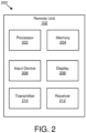
- Figure 2 depicts one embodiment of an apparatus 200 that may perform synchronization signal block selection.
- the apparatus 200 includes one embodiment of the remote unit 102.
- the remote unit 102 may include a processor 202, a memory 204, an input device 206, a display 208, a transmitter 210, and a receiver 212.
- the input device 206 and the display 208 are combined into a single device, such as a touchscreen.
- the remote unit 102 may not include any input device 206 and/or display 208.
- the remote unit 102 may include one or more of the processor 202, the memory 204, the transmitter 210, and the receiver 212, and may not include the input device 206 and/or the display 208.
- the processor 202 may include any known controller capable of executing computer-readable instructions and/or capable of performing logical operations.
- the processor 202 may be a microcontroller, a microprocessor, a central processing unit (“CPU”), a graphics processing unit (“GPU”), an auxiliary processing unit, a field programmable gate array (“FPGA”), or similar programmable controller.
- the processor 202 executes instructions stored in the memory 204 to perform the methods and routines described herein.
- the processor 202 may: detects at least one synchronization signal block of the multiple synchronization signal blocks; determine at least one synchronization signal frequency associated with the at least one detected synchronization signal block; select a first synchronization signal block of the at least one detected synchronization signal block and a first synchronization signal frequency of the at least one synchronization signal frequency, wherein the first synchronization signal block is associated with the first synchronization signal frequency; decode a first physical broadcast channel of the first synchronization signal block; and determine whether to reselect the first synchronization signal block based on a result of decoding the first physical broadcast channel.
- the processor 202 is communicatively coupled to the memory 204, the input device 206, the display 208, the transmitter 210, and the receiver 212.
- the memory 204 in one embodiment, is a computer readable storage medium.
- the memory 204 includes volatile computer storage media.
- the memory 204 may include a RAM, including dynamic RAM (“DRAM”), synchronous dynamic RAM (“SDRAM”), and/or static RAM (“SRAM”).
- the memory 204 includes non-volatile computer storage media.
- the memory 204 may include a hard disk drive, a flash memory, or any other suitable non-volatile computer storage device.
- the memory 204 includes both volatile and non-volatile computer storage media.
- the memory 204 also stores program code and related data, such as an operating system or other controller algorithms operating on the remote unit 102.
- the input device 206 may include any known computer input device including a touch panel, a button, a keyboard, a stylus, a microphone, or the like.
- the input device 206 may be integrated with the display 208, for example, as a touchscreen or similar touch-sensitive display.
- the input device 206 includes a touchscreen such that text may be input using a virtual keyboard displayed on the touchscreen and/or by handwriting on the touchscreen.
- the input device 206 includes two or more different devices, such as a keyboard and a touch panel.
- the display 208 may include any known electronically controllable display or display device.
- the display 208 may be designed to output visual, audible, and/or haptic signals.
- the display 208 includes an electronic display capable of outputting visual data to a user.
- the display 208 may include, but is not limited to, an LCD display, an LED display, an OLED display, a projector, or similar display device capable of outputting images, text, or the like to a user.
- the display 208 may include a wearable display such as a smart watch, smart glasses, a heads-up display, or the like.
- the display 208 may be a component of a smart phone, a personal digital assistant, a television, a table computer, a notebook (laptop) computer, a personal computer, a vehicle dashboard, or the like.
- the display 208 includes one or more speakers for producing sound.
- the display 208 may produce an audible alert or notification (e.g., a beep or chime).
- the display 208 includes one or more haptic devices for producing vibrations, motion, or other haptic feedback.
- all or portions of the display 208 may be integrated with the input device 206.
- the input device 206 and display 208 may form a touchscreen or similar touch-sensitive display.
- the display 208 may be located near the input device 206.
- the transmitter 210 is used to provide UL communication signals to the network unit 104 and the receiver 212 is used to receive DL communication signals from the network unit 104, as described herein.
- the receiver 212 may be used to receive multiple synchronization signal blocks on a first wideband carrier.
- each synchronization signal block of the multiple synchronization signal blocks includes at least one synchronization signal and a physical broadcast channel.
- the remote unit 102 may have any suitable number of transmitters 210 and receivers 212.
- the transmitter 210 and the receiver 212 may be any suitable type of transmitters and receivers.
- the transmitter 210 and the receiver 212 may be part of a transceiver.
- Figure 3 depicts one embodiment of an apparatus 300 that may be used for synchronization signal block selection.
- the apparatus 300 includes one embodiment of the network unit 104.
- the network unit 104 may include a processor 302, a memory 304, an input device 306, a display 308, a transmitter 310, and a receiver 312.
- the processor 302, the memory 304, the input device 306, the display 308, the transmitter 310, and the receiver 312 may be substantially similar to the processor 202, the memory 204, the input device 206, the display 208, the transmitter 210, and the receiver 212 of the remote unit 102, respectively.
- the network unit 104 may have any suitable number of transmitters 310 and receivers 312.
- the transmitter 310 and the receiver 312 may be any suitable type of transmitters and receivers.
- the transmitter 310 and the receiver 312 may be part of a transceiver.
- Figure 4 is a schematic block diagram illustrating one embodiment of a deployment of a system 400 including a wideband component carrier with multiple synchronization signal burst sets in frequency.
- the system 400 includes a first cell 402 and a second cell 404. As illustrated, the first cell 402 and the second cell 404 may overlap one another.
- the first cell 402 includes a first SS burst set 406, a second SS burst set 408, a third SS burst set 410, and a deactivated TRP 412. As may be appreciated, any of the first SS burst set 406, the second SS burst set 408, and the third SS burst set 410 may include multiple nodes.
- the second cell 404 includes a fourth SS burst set 414, a fifth SS burst set 416, a sixth SS burst set 418, and a seventh SS burst set 420. Again, any of the fourth SS burst set 414, the fifth SS burst set 416, the sixth SS burst set 418, and the seventh SS burst set 420 may include multiple nodes.
- a BWP having a group of contiguous PRBs may be used to support reduced UE BW capability, UE BW adaptation, FDM of multiple numerologies, and/or use of a non-contiguous spectrum.
- a connected mode UE may be UE-specifically and/or semi-statically configured with one or more active BWPs for a single wideband carrier.
- a bandwidth of a BWP equals or is smaller than a maximum UE bandwidth capability, but may be at least as large as a bandwidth of an SS block.
- the SS block may include primary SS, secondary SS, and/or PBCH.
- different UEs' BWPs may fully overlap or may partially overlap. In such embodiments, it may be up to a NE (e.g., gNB) to coordinate scheduling of different UEs' BWPs.
- configuration parameters of a BWP may include numerology (e.g., subcarrier spacing), a frequency location (e.g., center frequency), and/or a bandwidth (e.g., a number of PRBs).
- the BWP may contain an SS block, while in other embodiments, the BWP may not contain an SS block.
- multiple SS burst set transmissions may make a gNB able to more easily configure a UE.
- the UE may have a smaller operating bandwidth than a carrier bandwidth.
- the gNB may configure the UE with a BWP including one or more SS blocks and may allow the UE to detect and/or measure the one or more SS blocks without LO retuning.
- transmitting multiple SS burst sets on different SS raster frequencies of a wideband carrier may distribute UEs in idle or inactive mode across different SS burst sets and different common search spaces, thereby potentially reducing paging and/or random access related (e.g., message 2) load in each common search space.
- Described herein are various methods that may be used by a UE to efficiently measure multiple SS burst sets in frequency of a wideband CC and/or select one SS burst set of the wideband CC.
- multiple SS burst sets in frequency are transmitted on SS raster frequencies in a wideband carrier.
- the same PSS/SSS sequences may be employed for those SS burst sets to implicitly indicate to a UE an association of those SS burst sets.
- a few bits may be used to indicate indices of frequency-domain SS burst sets and may be included as payload of PBCH or RMSI.
- these indices may be used to construct extended physical cell IDs (e.g., in addition to a physical cell ID mapped to PSS/SSS sequences of the SS block) addressing multiple logical cells of a wideband CC.
- each logical cell may schedule any part of the wideband CC and may be associated with one SS burst set in frequency of the wideband CC.
- a payload of PBCH or RMSI may include an indication of a frequency separation and/or offset of a frequency-domain SS burst sets from a reference point (e.g., a center and/or edge of the wideband CC or reference SS raster frequency that may correspond to approximately the center and/or edge of the wideband CC or reference frequency-domain SS burst location and/or position) in terms of multiple SS raster steps or PRBs with subcarrier spacing equal to SS subcarrier spacing.
- an extended cell ID may be determined based on a frequency separation and/or offset indication (e.g., in addition to a cell ID mapped to PSS/SSS sequences of an SS block).
- a frequency-domain SS burst set index may be determined based on a frequency separation and/or offset indication (e.g., index 0 for reference frequency-domain SS burst set).
- another way to differentiate multiple SS burst sets in frequency of a wideband CC is to use different PSS/SSS sequences (e.g., using different physical cell IDs) on different SS blocks in different frequencies.
- UEs operated with a narrowband transceiver may be able to use only some frequency parts within a wideband CC at a given time.
- a number of SS burst sets in frequency for the wideband CC may need to be large enough to distribute narrowband UEs across multiple frequency parts of the wideband CC.
- signaling overhead in PBCH and radio resource overhead from multiple SS burst set transmissions in frequency may be taken into account.
- a maximum of approximately 4 to 8 SS block transmissions in frequency may be used (e.g., up to approximately 4 to 8 SS burst sets in frequency with approximately 2 to 3 bits for an indication in PBCH or RMSI).
- each frequency part within the wideband CC having a SS burst set may be self-discoverable.
- an idle mode UE may camp on one SS burst set in frequency of the wideband CC.
- the UE may camp on the SS burst set as long as a PBCH and/or an RMSI of the SS burst set indicates that a logical cell associated with the SS burst set is not barred for the UE to camp on it.
- not only connected mode UEs e.g., which may be informed of specific frequency locations of multiple SS burst sets of the wideband CC
- idle mode or initial access UEs which are not informed of specific frequency locations of multiple SS burst sets of the wideband CC may be able to combine multiple PSS/SSS sequence correlation outputs obtained from the different SS raster frequency locations (e.g., combining is up to UE implementation and may be when UE bandwidth spans multiple SS raster frequency locations with SS burst and SS burst on the multiple SS raster frequency locations are transmitted at the same time or overlapping time instances) and/or reduce cell detection latency.
- each SS burst set of multiple SS burst sets in frequency for a wideband CC may have a separate configuration in terms of SS burst set periodicity, a number of SS blocks per SS burst set (e.g., number of downlink transmit beams per SS burst set), SS transmit power, and/or SS block time locations (e.g., actually transmitted) within an SS burst set.
- multiple SS burst sets for a wideband CC may be transmitted from the same or from different (e.g., synchronized and coordinated) network nodes or TRPs depending on deployment scenarios as shown in Figure 4 , and accordingly separate configuration for each SS burst set of the wideband CC may be used.
- corresponding RMSI contents including configurations of SS burst set and RACH may be different per SS burst set in frequency. In such embodiments, the RMSI may be remaining essential system information not carried by PBCH.
- some logical cells of a wideband CC may be used less or not used for a given time duration.
- SS burst sets for those logical cells may be transmitted with longer periodicity.
- different network nodes for the wideband CC may have a different number of antenna groups and/or belong to different BS power classes, leading to different number of TX beams and/or different SS transmit power.
- some coordination may be used across frequency parts to avoid DL and/or UL interference.
- the node may coordinate time locations of transmitted SS blocks of the multiple SS burst sets to have common DL and/or UL regions across the frequency parts.
- it may be desired to define a separate configuration signaling for each SS burst set, in order to accommodate various deployment scenarios.
- an idle and/or inactive mode UE or initial access UE with a narrowband receiver may select an SS burst set in frequency and a corresponding logical cell.
- the UE may select the SS burst set in frequency and the corresponding logical cell based on RRM measurements and frequency location and/or bandwidth of a CORESET associated with a detected and selected SS block of the SS burst set.
- a common CORESET may be used to at least to schedule PDSCH carrying RMSI.
- the RMSI may be associated with the SS burst set.
- a UE selects one SS burst set in frequency among SS burst sets for which RSRP, RSRQ, and/or RS-SINR measurement results are above threshold values and transmissions of the SS burst set, the CORESET for RMSI scheduling, and/or PDSCH for RMSI delivery are confined within UE's operating BW.
- PBCH in a detected and/or selected SS block may indicate time and/or frequency location of the common CORESET.
- a UE may select an SS burst set in frequency which indicates UE's supported and/or preferred SCS for the common CORESET (and possibly UE specific CORESET, which may use the same SCS as the common CORESET).
- a NE may signal RSRP, RSRQ, and/or RS-SINR offset values (e.g., for different frequency-domain SS burst sets) which a UE may apply to rank SS burst sets in frequency in RMSI.
- RMSI of each SS burst set in frequency may include SS frequency-specific RSRP, RSRQ, and/or RS-SINR offset values for all the SS frequencies of the wideband CC so that the UE may re-select a serving SS frequency (e.g., a serving SS burst set in frequency) within the wideband CC without decoding RMSI of other SS burst sets in frequency.
- RSRP, RSRQ, and/or RS-SINR offset may be used for a NE to manage loads across multiple SS burst sets in frequency.
- an SS burst set index in frequency may implicitly indicate priority of each SS burst set and a corresponding logical cell. For example, a frequency-domain SS burst set with an index '0' may have a highest priority and logical cell selection priority may decrease with an increase of the frequency-domain SS burst set index number.
- a UE may select an SS burst set in frequency with a highest priority.
- an idle mode UE may generally camp on a frequency-domain SS burst set indexed with 0 (e.g., binary bits ⁇ 00').
- a UE may select an SS burst set in frequency which has a largest number of suitable SS blocks (e.g., a number of SS blocks for which the measurement values are above threshold values).
- a narrowband UE may select an SS burst set in frequency which has a shortest SS burst set periodicity among suitable SS burst sets in frequency.
- a network node configures a UE with a few (e.g., approximately 1 to 2) SMTCs per wideband CC.
- each SMTC may include indications on measurement window periodicity, measurement window duration, measurement window time offset, a subset of SS frequencies of the wideband CC, and/or SS frequency specific additional time offsets for the subset of SS frequencies of the wideband CC.
- SS frequencies of the wideband CC may be frequencies in which multiple SS burst sets in frequency are transmitted. In one example, all the SS frequencies of the wideband CC are SS raster frequencies in a given frequency band.
- the SS raster frequencies in the given frequency band are a set of frequencies that an initial access UE may scan in the given frequency band for cell search.
- some SS frequencies of the wideband CC are SS raster frequencies of the given frequency band, and other SS frequencies of the wideband CC are not SS raster frequencies.
- a UE connected to the wideband CC may have to frequently measure SS frequencies which are different from a current serving SS frequency but part of SS frequencies of the wideband CC.
- an allowed set of SS block time locations is common (e.g., in terms of absolute time) for the multiple SS burst sets.
- UEs with wideband receiver capability may be able to measure multiple SS frequencies, such as in embodiments in which the multiple SS burst sets are transmitted simultaneously.
- UEs operated with narrowband receivers may be able to measure only one (or a subset of) SS frequency at a given time. In such embodiments, it may take much longer time for the narrowband UEs to perform SS block based measurements on all the SS frequencies of the wideband CC than for wideband UEs.
- FIG. 5 is a timing diagram 500 illustrating one embodiment of multiple synchronization signal burst set transmissions in frequency for a wideband component carrier.
- the timing diagram 500 illustrates 240 kHz SCS for an SS block.
- the timing diagram 500 illustrates a first SS frequency 502, a second SS frequency 504, a third SS frequency 506, and a fourth SS frequency 508.
- On the first SS frequency 502, a first SS burst set 510 is transmitted at a first time 512.
- a second SS burst set 514 is transmitted to end at a second time 516.
- a first period 518 between the first time 512 and the second time 516 may be approximately 5 ms.
- a third SS burst set 520 is transmitted at a third time 522.
- a second period 524 between the second time 516 and the third time 522 may be approximately 5 ms.
- a fourth SS burst set 526 is transmitted to end at a fourth time 528.
- a third period 530 between the third time 522 and the fourth time 528 may be approximately 5 ms.
- a fifth SS burst set 532 (e.g., a repeat of the first SS burst set 510) is transmitted at a fifth time 534.
- a fourth period 536 between the fourth time 528 and the fifth time 534 may be approximately 5 ms.
- a sixth SS burst set 538 (e.g., a repeat of the second SS burst set 514) is transmitted to end at a sixth time 540.
- a fifth period 542 between the fifth time 534 and the sixth time 540 may be approximately 5 ms.
- the first SS burst set 510, the second SS burst set 514, the third SS burst set 520, and the fourth SS burst set 526 may continue to repeat any suitable number of times.
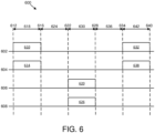
- FIG. 6 is a timing diagram 600 illustrating another embodiment of multiple synchronization signal burst set transmissions in frequency for a wideband component carrier.
- the timing diagram 600 illustrates 120 kHz SCS for an SS block.
- the timing diagram 600 illustrates a first SS frequency 602, a second SS frequency 604, a third SS frequency 606, and a fourth SS frequency 608.
- a first SS burst set 610 is transmitted at a first time 612.
- a second SS burst set 614 is transmitted.
- the first SS burst set 610 and the second SS burst set 614 end at approximately a second time 616.
- a first period 618 between the first time 612 and the second time 616 may be approximately 5 ms.
- a second period 624 between the second time 616 and the third time 622 may be approximately 5 ms.
- a fourth SS burst set 626 is transmitted at approximately the same time as the third SS burst set 620 and on the fourth SS frequency 608, a fourth SS burst set 626 is transmitted.
- the third SS burst set 620 and the fourth SS burst set 622 end at approximately a fourth time 628.
- a third period 630 between the third time 622 and the fourth time 628 may be approximately 5 ms.
- a fifth SS burst set 632 (e.g., a repeat of the first burst set 610) is transmitted at a fifth time 634.
- a fourth period 636 between the fourth time 628 and the fifth time 634 may be approximately 5 ms.
- a sixth SS burst set 638 (e.g., a repeat of the second burst set 614) is transmitted.
- the fifth SS burst set 632 and the sixth SS burst set 638 end at approximately a sixth time 640.
- a fifth period 642 between the fifth time 634 and the sixth time 640 may be approximately 5 ms.
- the first SS burst set 610, the second SS burst set 614, the third SS burst set 620, and the fourth SS burst set 626 may continue to repeat any suitable number of times.
- a NE applies slot-level or sub-frame-level SS frequency specific time offsets (with respect to a set of SS block time locations predefined per frequency band or with respect to a reference set of SS block time locations which is used by a "reference SS burst set" in frequency, e.g., frequency-domain SS burst set indexed with 0, or SS burst set transmitted on a SS raster frequency) to transmit the SS burst sets on the different SS frequencies of the wideband CC
- the narrowband UEs can also measure all the SS frequencies more quickly, especially for the SS burst sets with longer periodicities (e.g., 20 ms or longer).
- time offset values may be predefined depending on SCS of an SS block and/or periodicity of an SS burst set, and PBCH and/or RMSI may indicate an exact timing offset applied to each SS burst set.
- time offset values ⁇ 0 ms (for the first SS burst set 510), 2.5 ms (for the second SS burst set 514), 10 ms (for the third SS burst set 520), 12.5 ms (for the fourth SS burst set 526) ⁇ are allowed for SS block of 240 kHz SCS and SS burst set periodicity of 20 ms or longer.
- time offset values ⁇ 0, 2.5, 10, 12.5 ⁇ ms correspond to ⁇ 0, 40, 160, 200 ⁇ slots.
- time offset values ⁇ 0 ms for the first SS burst set 610), 0 ms (for the second SS burst set 614), 10 ms (for the third SS burst set 620), 10 ms (for the fourth SS burst set 626) ⁇ are allowed for SS block of 120 kHz SCS and SS burst set periodicity of 20 ms or longer.
- SS frequency specific time offset values applied and SS burst set periodicities may be indicated in respective RMSI for each SS burst set in frequency.
- narrowband UEs may not need to perform frequent measurements on non-serving SS frequencies of the wideband CC, and SS frequency specific time offset values may be set to zero for all the SS burst set in frequencies of the wideband CC.
- a connected mode UE may be configured with a separate SMTC per SS frequency of serving or non-serving wideband CC including separate measurement window periodicity, duration, and/or offset information.
- this may cause high signaling overhead for measurement configuration and may lead to too frequent measurement gaps for the narrowband UEs.
- a connected mode UE may receive a few SMTCs per wideband CC, each of which may include measurement window periodicity, duration, offset, associated SS frequencies of the wideband CC, and/or SS frequency specific additional time offsets for the associated SS frequencies.
- a connected mode UE is configured with a single BWP SCS which is different from a SCS of SS blocks (that may be predefined for a corresponding frequency band)
- SS blocks may not be transmitted on that BWP, but may be transmitted on another BWP configured with an SCS the same as the SCS of the SS block.
- the UE may have to retune its LO and adjust subcarrier spacing (and potentially sampling rate) for SS block based measurements.
- frequent LO retuning for intra-frequency measurement and time/frequency tracking may be avoided if a gNB configures the UE with CSI-RS based L3 measurement and tracking reference signal.
- the SS blocks of one SS burst set of the wideband carrier may be time-multiplexed or time/frequency-multiplexed with data and control channels of the different SCS (e.g., 120 kHz) within a frequency part.
- the UE may not need to retune LO, but may adjust operational subcarrier spacing (and potentially sampling rate) for SS block based measurements. In such embodiments, during SS block measurement the UE may not be able to receive data and control channels unless the UE supports simultaneous operation of two subcarrier spacings.
- an SS block time index within an SS burst set may be indicated based on a PBCH-DMRS sequence index (e.g., 3 bits for 8 possible PBCH DM-RS sequences) for low frequency bands (e.g., below 6 GHz).
- a PBCH-DMRS sequence index e.g., 3 bits for 8 possible PBCH DM-RS sequences
- additional bits e.g., 3 additional bits
- additional bits for an SS block time index e.g., 6 bits
- SS block time locations in an SS burst set may be indexed from 0 to L-1 in increasing order within a half radio frame.
- 3 LSBs of an SS block time index are indicated by 8 different PBCH-DMRS sequences ⁇ a_0, ..., a_7 ⁇ .
- 2 LSBs of SS block time index may be indicated by 4 different PBCH-DMRS sequences ⁇ b_0, ..., b_3 ⁇ with the one remaining bit out of 3 LSBs set to 0 and not transmitted by PBCH.
- ⁇ a_0, ...,a_3 ⁇ may be the same as ⁇ b_0, ..., b_3 ⁇ for a given cell ID indicated by PSS/SSS.
- direct SFN reading from a target cell may not be required for a UE.
- a SFN in included in PBCH and to support PRACH resource periodicity of larger than 10 ms (e.g., 20 ms)
- SFN even/odd synchronization between a serving cell and a target cell may be used.
- the UE may for handover purposes assume an absolute value of a relative time difference between radio frame i in the current serving cell and the target cell to be less than 5 ms (e.g., half of a 10 ms radio frame).
- half radio frame timing may be indicated in the PBCH which may be irrespective of SS burst set periodicity. This may be needed for an SS burst set periodicity of 5 ms.
- half radio frame even/odd synchronization (in addition to SFN even/odd synchronization) between a serving cell and a target cell may be used.
- the UE may for handover purposes assume an absolute value of the relative time difference between radio frame i in the current serving cell and the target cell to be less than 2.5 ms (e.g., half of a 5 ms half radio frame).
- detecting an SS block in an SS burst set may not provide adequate information for determining a slot index within which the SS block is detected. This may occur when a portion of the SS block time index is indicated in the PBCH (e.g., number of SS blocks more than 8 SS blocks, L > 8, SS blocks with subcarrier spacing larger than 30 kHz (e.g., 120 kHz, 240 kHz)).
- a PDSCH scrambling sequence generator initialization may not be based on the slot index.
- a PDSCH scrambling sequence generator initialization may be based on 3 LSB bits of the SS block time index or the PBCH-DMRS sequence index. In certain embodiments, a PDSCH scrambling sequence generator initialization may be based on a physical cell identity, a virtual cell identity, and/or a logical cell identity.
- a serving cell may provide an SS block time index (or a portion - e.g., 3 LSB bits of the SS block time index or a PBCH-DMRS sequence index) for a target cell, and a UE may perform random access on a RACH resource associated with the SS block time index.
- a UE may be enabled to perform random access on a RACH resource of any SS block with the same value of the 3 LSB bits of the SS block time index or the PBCH-DMRS sequence index.
- a serving cell may provide frequency-domain SS index in situations in which there are multiple SS blocks in frequency, as well as SS frequency specific additional time offsets for a target cell wideband CC.
- Figure 7 is a flow chart diagram illustrating one embodiment of a method 700 for synchronization signal block selection.
- the method 700 is performed by an apparatus, such as the remote unit 102.
- the method 700 may be performed by a processor executing program code, for example, a microcontroller, a microprocessor, a CPU, a GPU, an auxiliary processing unit, a FPGA, or the like.
- the method 700 may include receiving 702 multiple synchronization signal blocks on a first wideband carrier.
- each synchronization signal block of the multiple synchronization signal blocks includes at least one synchronization signal and a physical broadcast channel.
- the method 700 includes detecting 704 at least one synchronization signal block of the multiple synchronization signal blocks.
- the method 700 includes determining 706 at least one synchronization signal frequency associated with the at least one detected synchronization signal block.
- the method 700 includes selecting 708 a first synchronization signal block of the at least one detected synchronization signal block and a first synchronization signal frequency of the at least one synchronization signal frequency.
- the first synchronization signal block is associated with the first synchronization signal frequency.
- the method 700 includes decoding 710 a first physical broadcast channel of the first synchronization signal block. In some embodiments, the method 700 includes determining 712 whether to reselect the first synchronization signal block based on a result of decoding the first physical broadcast channel.
- multiple synchronization signal blocks are received on multiple synchronization signal frequencies of the first wideband carrier.
- the method 700 includes performing measurements on the at least one detected synchronization signal block.
- the first synchronization signal block is selected based on the measurements, and the measurements include at least one of reference signal received power, reference signal received quality, and reference signal signal-to-interference and noise ratio.
- the method 700 includes: receiving offset values selected from a group including reference signal received power, reference signal received quality, and reference signal signal-to-interference and noise ratio for the at least one detected synchronization signal frequency; and determining whether to reselect the first synchronization signal block based on the measurement results and the offset values corresponding to the at least one detected synchronization signal frequency.
- the method 700 includes, in response to determining to reselect the first synchronization signal block, reselecting a second synchronization signal block of the at least one detected synchronization signal block and a second synchronization signal frequency of the at least one synchronization signal frequency.
- the second synchronization signal block is associated with the second synchronization signal frequency.
- determining whether to reselect the first synchronization signal block is based on a subcarrier spacing value indicated in the first physical broadcast channel.
- a remote unit 102 may not support a certain SCS due to a certain configured carrier aggregation combination.
- determining whether to reselect the first synchronization signal block is based on a physical downlink control channel configuration for remaining minimum system information indicated in the first physical broadcast channel.
- the multiple synchronization signal blocks are associated with a common physical cell identity.
- the multiple synchronization signal blocks are associated with multiple physical cell identities.
- the multiple synchronization signal blocks are divided into multiple synchronization signal burst sets.
- At least two synchronization signal burst sets of the multiple synchronization signal burst sets include separate configurations.
- each configuration of the separate configurations includes parameters selected from a group including a burst set periodicity, a number of synchronization signal blocks per synchronization signal burst set, a transmission power, and a synchronization signal block time location within a burst set.
- the method 700 includes: establishing a radio resource control connection with a cell associated with the first synchronization signal block of the first synchronization signal frequency of the first wideband carrier; and receiving at least one synchronization signal block based measurement timing configuration for a second wideband carrier.
- the at least one synchronization signal block based measurement timing configuration includes a measurement window periodicity, a measurement window duration, a first measurement window offset, at least one associated synchronization signal frequency within the second wideband carrier, and a second measurement window offset corresponding to the at least one associated synchronization signal frequency.
- the first wideband carrier is the same as the second wideband carrier.
- the method 700 includes receiving indication of a synchronization signal frequency specific time offset value with respect to a synchronization signal time location for the first synchronization signal frequency of the first wideband carrier in the first physical broadcast channel or a physical downlink shared channel carrying remaining minimum system information.
- Figure 8 is a flow chart diagram illustrating one embodiment of a method 800 that may be used for synchronization signal block selection.
- the method 800 is performed by an apparatus, such as the network unit 104.
- the method 800 may be performed by a processor executing program code, for example, a microcontroller, a microprocessor, a CPU, a GPU, an auxiliary processing unit, a FPGA, or the like.
- the method 800 may include transmitting 802 multiple synchronization signal blocks on a first wideband carrier.
- each synchronization signal block of the multiple synchronization signal blocks includes at least one synchronization signal and a physical broadcast channel.
- the method 800 includes establishing 804 a radio resource control connection with a remote unit 102.
- the remote unit 102 may detect at least one synchronization signal block of the multiple synchronization signal blocks; determine at least one synchronization signal frequency associated with the at least one detected synchronization signal block; select a first synchronization signal block of the at least one detected synchronization signal block and a first synchronization signal frequency of the at least one synchronization signal frequency, wherein the first synchronization signal block is associated with the first synchronization signal frequency; decode a first physical broadcast channel of the first synchronization signal block; and determine whether to reselect the first synchronization signal block based on a result of decoding the first physical broadcast channel.
- the multiple synchronization signal blocks are transmitted on multiple synchronization signal frequencies of the first wideband carrier.
- the multiple synchronization signal blocks are associated with a common physical cell identity.
- the multiple synchronization signal blocks are associated with multiple physical cell identities.
- the multiple synchronization signal blocks are divided into multiple synchronization signal burst sets. In some embodiments, at least two synchronization signal burst sets of the multiple synchronization signal burst sets include separate configurations.
- each configuration of the separate configurations includes parameters selected from a group including a burst set periodicity, a number of synchronization signal blocks per synchronization signal burst set, a transmission power, and a synchronization signal block time location within a burst set.
- the method 800 includes transmitting at least one synchronization signal block based measurement timing configuration for a second wideband carrier, wherein the at least one synchronization signal block based measurement timing configuration includes a measurement window periodicity, a measurement window duration, a first measurement window offset, at least one associated synchronization signal frequency within the second wideband carrier, and a second measurement window offset corresponding to the at least one associated synchronization signal frequency.
- the first wideband carrier is the same as the second wideband carrier.
- the method 800 further includes transmitting offset values selected from a group comprising reference signal received power, reference signal received quality, and reference signal signal-to-interference and noise ratio for a synchronization signal frequency.
- the remote unit 102 determines whether to reselect a synchronization signal block based on measurement results and the offset values corresponding to the synchronization signal frequency.
- the method 800 includes transmitting information of a synchronization signal frequency specific time offset value of a synchronization signal block with respect to a reference synchronization signal block time location for the first wideband carrier in a physical broadcast channel of the synchronization signal block or a physical downlink shared channel carrying remaining minimum system information.
- a method comprises: receiving a plurality of synchronization signal blocks on a first wideband carrier, wherein each synchronization signal block of the plurality of synchronization signal blocks comprises at least one synchronization signal and a physical broadcast channel; detecting at least one synchronization signal block of the plurality of synchronization signal blocks; determining at least one synchronization signal frequency associated with the at least one detected synchronization signal block; selecting a first synchronization signal block of the at least one detected synchronization signal block and a first synchronization signal frequency of the at least one synchronization signal frequency, wherein the first synchronization signal block is associated with the first synchronization signal frequency; decoding a first physical broadcast channel of the first synchronization signal block; and determining whether to reselect the first synchronization signal block based on a result of decoding the first physical broadcast channel.
- the plurality of synchronization signal blocks is received on a plurality of synchronization signal frequencies of the first wideband carrier.
- a method further comprises performing measurements on the at least one detected synchronization signal block.
- the first synchronization signal block is selected based on the measurements, and the measurements include at least one of reference signal received power, reference signal received quality, and reference signal signal-to-interference and noise ratio.
- a method further comprises: receiving offset values selected from a group comprising reference signal received power, reference signal received quality, and reference signal signal-to-interference and noise ratio for the at least one detected synchronization signal frequency; and determining whether to reselect the first synchronization signal block based on the measurement results and the offset values corresponding to the at least one detected synchronization signal frequency.
- a method further comprises, in response to determining to reselect the first synchronization signal block, reselecting a second synchronization signal block of the at least one detected synchronization signal block and a second synchronization signal frequency of the at least one synchronization signal frequency, wherein the second synchronization signal block is associated with the second synchronization signal frequency.
- determining whether to reselect the first synchronization signal block is based on a subcarrier spacing value indicated in the first physical broadcast channel.
- determining whether to reselect the first synchronization signal block is based on a physical downlink control channel configuration for remaining minimum system information indicated in the first physical broadcast channel.
- a method further includes reselecting a synchronization signal block of the at least one detected synchronization signal block, and a cell associated with the reselected synchronization signal block has a greater number of synchronization signal blocks for which measurement values are above threshold values than other cells associated with other synchronization signal blocks of the at least one synchronization signal block.
- the plurality of synchronization signal blocks is associated with a common physical cell identity.
- the plurality of synchronization signal blocks is associated with a plurality of physical cell identities.
- the plurality of synchronization signal blocks is divided into a plurality of synchronization signal burst sets.
- At least two synchronization signal burst sets of the plurality of synchronization signal burst sets comprise separate configurations.
- each configuration of the separate configurations comprises parameters selected from a group comprising a burst set periodicity, a number of synchronization signal blocks per synchronization signal burst set, a transmission power, and a synchronization signal block time location within a burst set.
- a method comprises: establishing a radio resource control connection with a cell associated with the first synchronization signal block of the first synchronization signal frequency of the first wideband carrier; and receiving at least one synchronization signal block based measurement timing configuration for a second wideband carrier, wherein the at least one synchronization signal block based measurement timing configuration comprises a measurement window periodicity, a measurement window duration, a first measurement window offset, at least one associated synchronization signal frequency within the second wideband carrier, and a second measurement window offset corresponding to the at least one associated synchronization signal frequency.
- the first wideband carrier is the same as the second wideband carrier.
- a method further comprises receiving information of a synchronization signal frequency specific time offset value of a synchronization signal block with respect to a reference synchronization signal block time location for the first wideband carrier in a physical broadcast channel of the synchronization signal block or a physical downlink shared channel carrying remaining minimum system information.
- an apparatus comprises: a receiver that receives a plurality of synchronization signal blocks on a first wideband carrier, wherein each synchronization signal block of the plurality of synchronization signal blocks comprises at least one synchronization signal and a physical broadcast channel; and a processor that: detects at least one synchronization signal block of the plurality of synchronization signal blocks; determines at least one synchronization signal frequency associated with the at least one detected synchronization signal block; selects a first synchronization signal block of the at least one detected synchronization signal block and a first synchronization signal frequency of the at least one synchronization signal frequency, wherein the first synchronization signal block is associated with the first synchronization signal frequency; decodes a first physical broadcast channel of the first synchronization signal block; and determines whether to reselect the first synchronization signal block based on a result of decoding the first physical broadcast channel.
- the plurality of synchronization signal blocks is received on a plurality of synchronization signal frequencies of the first wideband carrier.
- the processor performs measurements on the at least one detected synchronization signal block.
- the first synchronization signal block is selected based on the measurements, and the measurements include at least one of reference signal received power, reference signal received quality, and reference signal signal-to-interference and noise ratio.
- the receiver receives offset values selected from a group comprising reference signal received power, reference signal received quality, and reference signal signal-to-interference and noise ratio for the at least one detected synchronization signal frequency, and the processor determines whether to reselect the first synchronization signal block based on the measurement results and the offset values corresponding to the at least one detected synchronization signal frequency.
- an apparatus further comprises, in response to determining to reselect the first synchronization signal block, the processor reselecting a second synchronization signal block of the at least one detected synchronization signal block and a second synchronization signal frequency of the at least one synchronization signal frequency, wherein the second synchronization signal block is associated with the second synchronization signal frequency.
- the processor determines whether to reselect the first synchronization signal block based on a subcarrier spacing value indicated in the first physical broadcast channel.
- the processor determines whether to reselect the first synchronization signal block based on a physical downlink control channel configuration for remaining minimum system information indicated in the first physical broadcast channel.
- the processer reselects a synchronization signal block of the at least one detected synchronization signal block, and a cell associated with the reselected synchronization signal block has a greater number of synchronization signal blocks for which measurement values are above threshold values than other cells associated with other synchronization signal blocks of the at least one detected synchronization signal block.
- the plurality of synchronization signal blocks is associated with a common physical cell identity.
- the plurality of synchronization signal blocks is associated with a plurality of physical cell identities.
- the plurality of synchronization signal blocks is divided into a plurality of synchronization signal burst sets.
- At least two synchronization signal burst sets of the plurality of synchronization signal burst sets comprise separate configurations.
- each configuration of the separate configurations comprises parameters selected from a group comprising a burst set periodicity, a number of synchronization signal blocks per synchronization signal burst set, a transmission power, and a synchronization signal block time location within a burst set.
- the processor establishes a radio resource control connection with a cell associated with the first synchronization signal block of the first synchronization signal frequency of the first wideband carrier
- the receiver receives at least one synchronization signal block based measurement timing configuration for a second wideband carrier
- the at least one synchronization signal block based measurement timing configuration comprises a measurement window periodicity, a measurement window duration, a first measurement window offset, at least one associated synchronization signal frequency within the second wideband carrier, and a second measurement window offset corresponding to the at least one associated synchronization signal frequency.
- the first wideband carrier is the same as the second wideband carrier.
- the receiver receives information of a synchronization signal frequency specific time offset value of a synchronization signal block with respect to a reference synchronization signal block time location for the first wideband carrier in a physical broadcast channel of the synchronization signal block or a physical downlink shared channel carrying remaining minimum system information.
Landscapes
- Engineering & Computer Science (AREA)
- Signal Processing (AREA)
- Computer Networks & Wireless Communication (AREA)
- Databases & Information Systems (AREA)
- Mobile Radio Communication Systems (AREA)
- Computer Security & Cryptography (AREA)
- Physics & Mathematics (AREA)
- Mathematical Physics (AREA)
- Circuits Of Receivers In General (AREA)
- Two-Way Televisions, Distribution Of Moving Picture Or The Like (AREA)
- Synchronisation In Digital Transmission Systems (AREA)
Applications Claiming Priority (3)
| Application Number | Priority Date | Filing Date | Title |
|---|---|---|---|
| US201762549286P | 2017-08-23 | 2017-08-23 | |
| EP18811949.9A EP3673688B1 (de) | 2017-08-23 | 2018-08-23 | Auswahl eines synchronisationssignalblocks |
| PCT/US2018/047803 WO2019040779A1 (en) | 2017-08-23 | 2018-08-23 | SELECTING SYNCHRONIZATION SIGNAL BLOCKS |
Related Parent Applications (2)
| Application Number | Title | Priority Date | Filing Date |
|---|---|---|---|
| EP18811949.9A Division-Into EP3673688B1 (de) | 2017-08-23 | 2018-08-23 | Auswahl eines synchronisationssignalblocks |
| EP18811949.9A Division EP3673688B1 (de) | 2017-08-23 | 2018-08-23 | Auswahl eines synchronisationssignalblocks |
Publications (2)
| Publication Number | Publication Date |
|---|---|
| EP4407917A2 true EP4407917A2 (de) | 2024-07-31 |
| EP4407917A3 EP4407917A3 (de) | 2024-10-30 |
Family
ID=64564945
Family Applications (2)
| Application Number | Title | Priority Date | Filing Date |
|---|---|---|---|
| EP18811949.9A Active EP3673688B1 (de) | 2017-08-23 | 2018-08-23 | Auswahl eines synchronisationssignalblocks |
| EP24181639.6A Pending EP4407917A3 (de) | 2017-08-23 | 2018-08-23 | Synchronisationssignalblockauswahl |
Family Applications Before (1)
| Application Number | Title | Priority Date | Filing Date |
|---|---|---|---|
| EP18811949.9A Active EP3673688B1 (de) | 2017-08-23 | 2018-08-23 | Auswahl eines synchronisationssignalblocks |
Country Status (5)
| Country | Link |
|---|---|
| US (4) | US10716079B2 (de) |
| EP (2) | EP3673688B1 (de) |
| KR (3) | KR102698464B1 (de) |
| CN (2) | CN110999429B (de) |
| WO (1) | WO2019040779A1 (de) |
Families Citing this family (45)
| Publication number | Priority date | Publication date | Assignee | Title |
|---|---|---|---|---|
| JP6983158B2 (ja) * | 2016-07-15 | 2021-12-17 | 株式会社Nttドコモ | 端末、無線通信方法、基地局及びシステム |
| US10820225B2 (en) | 2017-05-05 | 2020-10-27 | Motorola Mobility Llc | Method and apparatus for transmitting a RACH preamble on a wireless network |
| KR102369471B1 (ko) * | 2017-08-07 | 2022-03-03 | 삼성전자 주식회사 | 무선 통신 시스템에서 추가적인 상향링크 주파수를 지원하기 위한 방법 및 장치 |
| WO2019040779A1 (en) * | 2017-08-23 | 2019-02-28 | Lenovo (Singapore) Pte. Ltd. | SELECTING SYNCHRONIZATION SIGNAL BLOCKS |
| KR102778360B1 (ko) * | 2017-09-06 | 2025-03-10 | 한국전자통신연구원 | 통신 시스템에서 시스템 정보의 송수신 방법 |
| US11463968B2 (en) * | 2017-09-17 | 2022-10-04 | Qualcomm Incorporated | Techniques for signaling synchronization signal burst set patterns |
| WO2019070091A1 (ko) * | 2017-10-02 | 2019-04-11 | 엘지전자 주식회사 | Lte와 nr간의 이중 연결에서 상향링크를 전송하는 방법 및 사용자 장치 |
| WO2019080120A1 (zh) * | 2017-10-27 | 2019-05-02 | Oppo广东移动通信有限公司 | 无线通信方法和设备 |
| PL3694271T3 (pl) * | 2017-11-01 | 2022-11-28 | Guangdong Oppo Mobile Telecommunications Corp., Ltd. | Sposób i urządzenie do transmisji informacji |
| US10848363B2 (en) * | 2017-11-09 | 2020-11-24 | Qualcomm Incorporated | Frequency division multiplexing for mixed numerology |
| US10880867B2 (en) * | 2017-11-17 | 2020-12-29 | Qualcomm Incorporated | Selecting a new radio uplink resource to transmit a random access procedure communication |
| KR101999702B1 (ko) | 2017-11-17 | 2019-07-12 | 엘지전자 주식회사 | 하향링크 채널을 송수신하는 방법 및 이를 위한 장치 |
| US11012996B2 (en) * | 2017-11-27 | 2021-05-18 | Telefonaktiebolaget Lm Ericsson (Publ) | Devices and methods for scheduling data transmissions in a wireless communication system |
| US11050598B2 (en) * | 2017-11-28 | 2021-06-29 | Qualcomm Incorporated | Carrier information signaling in a 5G network |
| KR102606801B1 (ko) * | 2017-12-26 | 2023-11-27 | 삼성전자주식회사 | 무선 통신 시스템의 초기 접속 방법 및 장치 |
| CN111587598A (zh) * | 2018-01-11 | 2020-08-25 | 株式会社Ntt都科摩 | 用户终端以及无线通信方法 |
| US11012197B2 (en) * | 2018-01-12 | 2021-05-18 | Apple Inc. | Resource set configurations using automatic repeat request information |
| WO2019144398A1 (zh) * | 2018-01-29 | 2019-08-01 | Oppo广东移动通信有限公司 | 控制ue搜索小区的方法、ue及网络设备 |
| US10932147B2 (en) * | 2018-03-30 | 2021-02-23 | Mediatek Inc. | Gap-based cell measurement in wireless communication system |
| CN118215061A (zh) * | 2018-05-10 | 2024-06-18 | 株式会社Ntt都科摩 | 用户终端 |
| US12052704B2 (en) * | 2018-05-10 | 2024-07-30 | Interdigital Patent Holdings, Inc. | Mechanism for SSB transmission in NR-U |
| KR102785895B1 (ko) | 2018-11-16 | 2025-03-25 | 삼성전자주식회사 | 참조 신호 수신 방법 및 이를 위한 전자 장치 |
| CN111757338B (zh) * | 2019-03-27 | 2023-04-28 | 华为技术有限公司 | 一种测量参考信号的方法及设备 |
| CN115052354B (zh) * | 2019-03-29 | 2024-02-13 | 中兴通讯股份有限公司 | 传输方法、装置、设备、系统和存储介质 |
| US11696142B2 (en) | 2019-04-04 | 2023-07-04 | Samsung Electronics Co., Ltd. | Method and apparatus for resource mapping of PDSCH on unlicensed spectrum |
| US11558735B2 (en) * | 2019-04-19 | 2023-01-17 | Qualcomm Incorporated | Carrier aggregation capability framework |
| US11419147B2 (en) | 2019-06-03 | 2022-08-16 | Qualcomm Incorporated | Beam association in random access procedures |
| US12267260B2 (en) * | 2019-07-15 | 2025-04-01 | Nokia Technologies Oy | Synchronization signaling block compatible interference coordination patterns to reduce interference in wireless networks |
| CN114080851B (zh) * | 2019-08-14 | 2025-09-19 | 株式会社Kt | 在非许可频段中收发数据的方法和设备 |
| WO2021044602A1 (ja) * | 2019-09-05 | 2021-03-11 | 株式会社Nttドコモ | 端末及び通信方法 |
| EP4213432A1 (de) * | 2019-09-30 | 2023-07-19 | Guangdong Oppo Mobile Telecommunications Corp., Ltd. | Drahtloskommunikationsverfahren und endgerätevorrichtung |
| US10979979B1 (en) | 2019-11-22 | 2021-04-13 | Qualcomm Incorporated | Synchronization signal block (SSB) measurements based on a measurement cycle frequency |
| WO2021111620A1 (ja) * | 2019-12-06 | 2021-06-10 | 株式会社Nttドコモ | 端末及び測定報告送信方法 |
| US11653389B2 (en) * | 2019-12-20 | 2023-05-16 | Qualcomm Incorporated | Methods and apparatus for indicating and switching UE capabilities |
| CN114846871B (zh) * | 2019-12-31 | 2025-05-09 | 华为技术有限公司 | 一种通信方法和装置 |
| CN114946247B (zh) * | 2020-01-22 | 2025-03-11 | 高通股份有限公司 | 用于能力降低的用户设备的下行链路跳频通信的方法和装置 |
| US11751150B2 (en) * | 2020-02-19 | 2023-09-05 | Qualcomm Incorporated | Synchronization signal block indexing schemes |
| CN112153734B (zh) * | 2020-09-29 | 2024-11-12 | 姚建业 | 用于区块链系统的智慧城市大数据信息的传输方法及系统 |
| WO2022077441A1 (en) * | 2020-10-16 | 2022-04-21 | Qualcomm Incorporated | Reference signal for unconnected mode ues and configuration thereof |
| CN115707359B (zh) * | 2021-05-20 | 2026-01-02 | 北京小米移动软件有限公司 | 参数配置方法及装置、电子设备及存储介质 |
| KR20240024055A (ko) * | 2021-06-23 | 2024-02-23 | 지티이 코포레이션 | 참조 시그널링 설계 및 구성을 위한 시스템 및 방법 |
| CN113973204B (zh) * | 2021-09-26 | 2024-11-22 | 西安交通大学 | 一种mimo-noma系统的非线性预编码方法及系统 |
| EP4161131B1 (de) | 2021-10-04 | 2024-07-10 | EXFO Oy | Ad-hoc-funkbasisstation, verfahren und computerprogramm |
| CN113746774B (zh) * | 2021-11-08 | 2021-12-28 | 成都星联芯通科技有限公司 | 一种信号获取方法、装置、设备及存储介质 |
| US12610332B2 (en) * | 2023-05-04 | 2026-04-21 | Raytheon Applied Signal Technology, Inc. | Optimizing cell searching in 5G new radio wireless networks or other wireless networks |
Family Cites Families (26)
| Publication number | Priority date | Publication date | Assignee | Title |
|---|---|---|---|---|
| DE10057499A1 (de) * | 2000-11-20 | 2002-06-06 | Siemens Ag | Verfahren zur Signalisierung des Diversity-Modes ein oder mehrerer Broadcast-Kanäle sowie zugehöriges Funkkommunikationssystem |
| US8014311B2 (en) * | 2009-06-08 | 2011-09-06 | Telefonaktiebolaget L M Ericsson (Publ) | Signal measurements based on sync signals |
| US8582527B2 (en) * | 2011-07-01 | 2013-11-12 | Ofinno Technologies, Llc | Hybrid automatic repeat request in multicarrier systems |
| US20140204851A1 (en) * | 2013-01-18 | 2014-07-24 | Qualcomm Incorporated | Enhanced physical broadcast channel for new carrier type in long term evolution |
| CN105164965A (zh) * | 2013-03-21 | 2015-12-16 | Lg电子株式会社 | 广播信道方法、用于收发广播信道信号的方法以及支持其的设备 |
| US10638435B2 (en) * | 2014-07-30 | 2020-04-28 | Lg Electronics Inc. | Method and device for performing device-to-device synchronization in wireless communication system |
| US9621340B1 (en) * | 2014-12-07 | 2017-04-11 | Lekha Wireless Solutions Pvt Ltd. | Method and device for detecting primary synchronization signal in LTE and LTE advanced communication system |
| US10178612B2 (en) * | 2016-04-26 | 2019-01-08 | Qualcomm Incorporated | Enhanced machine-type communications cell acquisition using narrow band synchronization channel |
| KR102677807B1 (ko) * | 2016-05-09 | 2024-06-25 | 삼성전자주식회사 | 무선 셀룰라 통신 시스템의 동기신호 송수신 방법 및 장치 |
| US10356675B2 (en) * | 2016-08-09 | 2019-07-16 | Qualcomm Incorporated | Handover candidate cell identification and radio link failure (RLF) mitigation in coverage areas |
| US11855821B2 (en) * | 2016-09-30 | 2023-12-26 | Nec Corporation | Methods and apparatuses for synchronous signal transmission |
| GB2555790A (en) * | 2016-11-08 | 2018-05-16 | Fujitsu Ltd | Cell search and synchronization in 5G |
| EP3516905B1 (de) * | 2017-03-24 | 2020-10-07 | Telefonaktiebolaget LM Ericsson (publ) | Messfenster für zellneuauswahl in new radio |
| CN110892763A (zh) * | 2017-05-03 | 2020-03-17 | Idac控股公司 | 用于新无线电(nr)中的寻呼过程的方法和设备 |
| US10666485B2 (en) * | 2017-05-03 | 2020-05-26 | Apple Inc. | Synchronization signal block index signaling |
| CN114900890B (zh) * | 2017-05-05 | 2025-03-21 | 北京三星通信技术研究有限公司 | 基站、终端及随机接入前导检测、随机接入信道配置方法 |
| US10270573B2 (en) * | 2017-05-16 | 2019-04-23 | Qualcomm Incorporated | Techniques and apparatuses for reusing remaining minimum system information configuration bits to signal a synchronization signal block location |
| US12075370B2 (en) * | 2017-06-13 | 2024-08-27 | Qualcomm Incorporated | Signaling for detected synchronization signal blocks |
| KR102352364B1 (ko) * | 2017-06-15 | 2022-01-18 | 주식회사 아이티엘 | Nr 시스템에서 광대역 동작 방법 및 장치 |
| CN109309955B (zh) * | 2017-07-28 | 2021-02-09 | 华为技术有限公司 | 一种同步信号块的传输方法、接入网设备及终端设备 |
| WO2019022574A1 (ko) * | 2017-07-28 | 2019-01-31 | 엘지전자 주식회사 | 동기 신호 블록을 송수신하는 방법 및 이를 위한 장치 |
| US10939394B2 (en) * | 2017-07-28 | 2021-03-02 | Qualcomm Incorporated | Measurement synchronization signals (SS) |
| US10278184B2 (en) * | 2017-08-10 | 2019-04-30 | At&T Intellectual Property I, L.P. | Radio resource management framework for 5G or other next generation network |
| US10887939B2 (en) * | 2017-08-10 | 2021-01-05 | Comcast Cable Communications, Llc | Transmission power control for beam failure recovery requests |
| US10651913B2 (en) * | 2017-08-10 | 2020-05-12 | Ofinno, Llc | Beam refinement during RACH |
| WO2019040779A1 (en) * | 2017-08-23 | 2019-02-28 | Lenovo (Singapore) Pte. Ltd. | SELECTING SYNCHRONIZATION SIGNAL BLOCKS |
-
2018
- 2018-08-23 WO PCT/US2018/047803 patent/WO2019040779A1/en not_active Ceased
- 2018-08-23 KR KR1020237044212A patent/KR102698464B1/ko active Active
- 2018-08-23 KR KR1020207004838A patent/KR102618030B1/ko active Active
- 2018-08-23 CN CN201880053563.3A patent/CN110999429B/zh active Active
- 2018-08-23 CN CN202211673353.9A patent/CN116347585A/zh active Pending
- 2018-08-23 US US16/110,316 patent/US10716079B2/en active Active
- 2018-08-23 KR KR1020247027884A patent/KR20240129625A/ko active Pending
- 2018-08-23 EP EP18811949.9A patent/EP3673688B1/de active Active
- 2018-08-23 EP EP24181639.6A patent/EP4407917A3/de active Pending
-
2020
- 2020-06-30 US US16/917,563 patent/US11297582B2/en active Active
-
2022
- 2022-03-30 US US17/709,109 patent/US11751154B2/en active Active
-
2023
- 2023-07-18 US US18/354,242 patent/US12232064B2/en active Active
Also Published As
| Publication number | Publication date |
|---|---|
| EP3673688B1 (de) | 2024-07-24 |
| KR102618030B1 (ko) | 2023-12-27 |
| KR102698464B1 (ko) | 2024-08-26 |
| CN116347585A (zh) | 2023-06-27 |
| CN110999429A (zh) | 2020-04-10 |
| KR20240001287A (ko) | 2024-01-03 |
| US10716079B2 (en) | 2020-07-14 |
| EP3673688A1 (de) | 2020-07-01 |
| CN110999429B (zh) | 2022-12-30 |
| EP3673688C0 (de) | 2024-07-24 |
| US12232064B2 (en) | 2025-02-18 |
| US20200337007A1 (en) | 2020-10-22 |
| KR20200038946A (ko) | 2020-04-14 |
| US20230362855A1 (en) | 2023-11-09 |
| US20220225256A1 (en) | 2022-07-14 |
| KR20240129625A (ko) | 2024-08-27 |
| US20190069256A1 (en) | 2019-02-28 |
| EP4407917A3 (de) | 2024-10-30 |
| US11297582B2 (en) | 2022-04-05 |
| WO2019040779A1 (en) | 2019-02-28 |
| US11751154B2 (en) | 2023-09-05 |
Similar Documents
| Publication | Publication Date | Title |
|---|---|---|
| US12232064B2 (en) | Synchronization signal block selection | |
| US12052767B2 (en) | Random access configuration | |
| EP3574701B1 (de) | Ressourcenkonfigurationprioritätsstufen | |
| US11659508B2 (en) | Configuring synchronization signal blocks having different power levels | |
| US11937307B2 (en) | Transmission beam indicating | |
| EP3688907B1 (de) | Rückkopplungsnachricht mit einer sequenz, die rückkopplungsinformationen anzeigt, die datenblöcken entsprechen | |
| WO2018145225A1 (en) | Semi-persistent transmission | |
| US11265806B2 (en) | Determining discovery announcement pool | |
| WO2018129690A1 (en) | Downlink configuration | |
| WO2018126404A1 (en) | Beam quality determination |
Legal Events
| Date | Code | Title | Description |
|---|---|---|---|
| PUAI | Public reference made under article 153(3) epc to a published international application that has entered the european phase |
Free format text: ORIGINAL CODE: 0009012 |
|
| STAA | Information on the status of an ep patent application or granted ep patent |
Free format text: STATUS: THE APPLICATION HAS BEEN PUBLISHED |
|
| AC | Divisional application: reference to earlier application |
Ref document number: 3673688 Country of ref document: EP Kind code of ref document: P |
|
| AK | Designated contracting states |
Kind code of ref document: A2 Designated state(s): AL AT BE BG CH CY CZ DE DK EE ES FI FR GB GR HR HU IE IS IT LI LT LU LV MC MK MT NL NO PL PT RO RS SE SI SK SM TR |
|
| REG | Reference to a national code |
Ref country code: DE Ref legal event code: R079 Free format text: PREVIOUS MAIN CLASS: H04L0005000000 Ipc: H04W0056000000 |
|
| PUAL | Search report despatched |
Free format text: ORIGINAL CODE: 0009013 |
|
| AK | Designated contracting states |
Kind code of ref document: A3 Designated state(s): AL AT BE BG CH CY CZ DE DK EE ES FI FR GB GR HR HU IE IS IT LI LT LU LV MC MK MT NL NO PL PT RO RS SE SI SK SM TR |
|
| RIC1 | Information provided on ipc code assigned before grant |
Ipc: H04L 5/00 20060101ALI20240923BHEP Ipc: H04W 56/00 20090101AFI20240923BHEP |
|
| STAA | Information on the status of an ep patent application or granted ep patent |
Free format text: STATUS: REQUEST FOR EXAMINATION WAS MADE |
|
| 17P | Request for examination filed |
Effective date: 20250327 |