EP4407941A1 - Procédé et appareil de communication - Google Patents
Procédé et appareil de communication Download PDFInfo
- Publication number
- EP4407941A1 EP4407941A1 EP22897904.3A EP22897904A EP4407941A1 EP 4407941 A1 EP4407941 A1 EP 4407941A1 EP 22897904 A EP22897904 A EP 22897904A EP 4407941 A1 EP4407941 A1 EP 4407941A1
- Authority
- EP
- European Patent Office
- Prior art keywords
- signal
- symbol
- fourier transform
- matrix
- modulation
- Prior art date
- Legal status (The legal status is an assumption and is not a legal conclusion. Google has not performed a legal analysis and makes no representation as to the accuracy of the status listed.)
- Pending
Links
- 238000004891 communication Methods 0.000 title claims abstract description 123
- 238000000034 method Methods 0.000 title claims abstract description 97
- 239000011159 matrix material Substances 0.000 claims description 94
- 239000013256 coordination polymer Substances 0.000 claims description 77
- 238000007493 shaping process Methods 0.000 claims description 71
- 238000012545 processing Methods 0.000 claims description 37
- 125000004122 cyclic group Chemical group 0.000 claims description 36
- 238000001228 spectrum Methods 0.000 claims description 32
- 238000005316 response function Methods 0.000 claims description 23
- 238000004590 computer program Methods 0.000 claims description 18
- 230000003595 spectral effect Effects 0.000 abstract description 36
- 230000006870 function Effects 0.000 description 48
- 230000011664 signaling Effects 0.000 description 47
- 230000005540 biological transmission Effects 0.000 description 38
- 238000013461 design Methods 0.000 description 35
- 230000000875 corresponding effect Effects 0.000 description 28
- 230000000694 effects Effects 0.000 description 22
- 238000010586 diagram Methods 0.000 description 18
- 230000008569 process Effects 0.000 description 8
- 238000010295 mobile communication Methods 0.000 description 6
- 230000008054 signal transmission Effects 0.000 description 6
- 238000006243 chemical reaction Methods 0.000 description 5
- 230000003287 optical effect Effects 0.000 description 5
- 230000007774 longterm Effects 0.000 description 4
- 230000010363 phase shift Effects 0.000 description 4
- 230000003068 static effect Effects 0.000 description 4
- 230000001360 synchronised effect Effects 0.000 description 4
- 230000008878 coupling Effects 0.000 description 3
- 238000010168 coupling process Methods 0.000 description 3
- 238000005859 coupling reaction Methods 0.000 description 3
- 238000001914 filtration Methods 0.000 description 3
- 238000003491 array Methods 0.000 description 2
- 230000003190 augmentative effect Effects 0.000 description 2
- 230000001413 cellular effect Effects 0.000 description 2
- 230000008859 change Effects 0.000 description 2
- 235000019800 disodium phosphate Nutrition 0.000 description 2
- 238000005516 engineering process Methods 0.000 description 2
- 238000013507 mapping Methods 0.000 description 2
- 238000005259 measurement Methods 0.000 description 2
- 230000004044 response Effects 0.000 description 2
- 239000004065 semiconductor Substances 0.000 description 2
- 238000004088 simulation Methods 0.000 description 2
- 230000003321 amplification Effects 0.000 description 1
- 239000000969 carrier Substances 0.000 description 1
- 239000003795 chemical substances by application Substances 0.000 description 1
- 230000002596 correlated effect Effects 0.000 description 1
- 238000013500 data storage Methods 0.000 description 1
- 230000003247 decreasing effect Effects 0.000 description 1
- 238000011161 development Methods 0.000 description 1
- 238000003199 nucleic acid amplification method Methods 0.000 description 1
- 230000003362 replicative effect Effects 0.000 description 1
Images


Classifications
-
- H—ELECTRICITY
- H04—ELECTRIC COMMUNICATION TECHNIQUE
- H04L—TRANSMISSION OF DIGITAL INFORMATION, e.g. TELEGRAPHIC COMMUNICATION
- H04L27/00—Modulated-carrier systems
- H04L27/32—Carrier systems characterised by combinations of two or more of the types covered by groups H04L27/02, H04L27/10, H04L27/18 or H04L27/26
- H04L27/34—Amplitude- and phase-modulated carrier systems, e.g. quadrature-amplitude modulated carrier systems
- H04L27/3405—Modifications of the signal space to increase the efficiency of transmission, e.g. reduction of the bit error rate, bandwidth, or average power
-
- H—ELECTRICITY
- H04—ELECTRIC COMMUNICATION TECHNIQUE
- H04L—TRANSMISSION OF DIGITAL INFORMATION, e.g. TELEGRAPHIC COMMUNICATION
- H04L25/00—Baseband systems
- H04L25/02—Details ; arrangements for supplying electrical power along data transmission lines
- H04L25/03—Shaping networks in transmitter or receiver, e.g. adaptive shaping networks
- H04L25/03828—Arrangements for spectral shaping; Arrangements for providing signals with specified spectral properties
- H04L25/03834—Arrangements for spectral shaping; Arrangements for providing signals with specified spectral properties using pulse shaping
-
- H—ELECTRICITY
- H04—ELECTRIC COMMUNICATION TECHNIQUE
- H04L—TRANSMISSION OF DIGITAL INFORMATION, e.g. TELEGRAPHIC COMMUNICATION
- H04L27/00—Modulated-carrier systems
- H04L27/26—Systems using multi-frequency codes
- H04L27/2601—Multicarrier modulation systems
- H04L27/2602—Signal structure
- H04L27/2605—Symbol extensions, e.g. Zero Tail, Unique Word [UW]
-
- H—ELECTRICITY
- H04—ELECTRIC COMMUNICATION TECHNIQUE
- H04L—TRANSMISSION OF DIGITAL INFORMATION, e.g. TELEGRAPHIC COMMUNICATION
- H04L27/00—Modulated-carrier systems
- H04L27/26—Systems using multi-frequency codes
- H04L27/2601—Multicarrier modulation systems
- H04L27/2647—Arrangements specific to the receiver only
- H04L27/2649—Demodulators
- H04L27/26534—Pulse-shaped multi-carrier, i.e. not using rectangular window
- H04L27/26536—Filtering over the entire frequency band, e.g. filtered orthogonal frequency division multiplexing [OFDM]
-
- H—ELECTRICITY
- H04—ELECTRIC COMMUNICATION TECHNIQUE
- H04L—TRANSMISSION OF DIGITAL INFORMATION, e.g. TELEGRAPHIC COMMUNICATION
- H04L27/00—Modulated-carrier systems
- H04L27/32—Carrier systems characterised by combinations of two or more of the types covered by groups H04L27/02, H04L27/10, H04L27/18 or H04L27/26
- H04L27/34—Amplitude- and phase-modulated carrier systems, e.g. quadrature-amplitude modulated carrier systems
- H04L27/3494—Amplitude- and phase-modulated carrier systems, e.g. quadrature-amplitude modulated carrier systems using non - square modulating pulses, e.g. using raised cosine pulses; Partial response QAM, i.e. with partial response pulse shaping
-
- H—ELECTRICITY
- H04—ELECTRIC COMMUNICATION TECHNIQUE
- H04L—TRANSMISSION OF DIGITAL INFORMATION, e.g. TELEGRAPHIC COMMUNICATION
- H04L27/00—Modulated-carrier systems
- H04L27/26—Systems using multi-frequency codes
- H04L27/2601—Multicarrier modulation systems
- H04L27/2626—Arrangements specific to the transmitter only
- H04L27/2627—Modulators
- H04L27/2634—Inverse fast Fourier transform [IFFT] or inverse discrete Fourier transform [IDFT] modulators in combination with other circuits for modulation
- H04L27/2636—Inverse fast Fourier transform [IFFT] or inverse discrete Fourier transform [IDFT] modulators in combination with other circuits for modulation with FFT or DFT modulators, e.g. standard single-carrier frequency-division multiple access [SC-FDMA] transmitter or DFT spread orthogonal frequency division multiplexing [DFT-SOFDM]
Definitions
- the application relates to the communication field, and in particular, to a communication method and apparatus.
- Nyquist Nyquist
- FTN faster-than-Nyquist
- a transmission rate of Nyquist signaling (referred to as a Nyquist signaling rate below) is an ultimate transmission rate of intersymbol interference-free transmission.
- a transmission rate of FTN is greater than the Nyquist signaling rate, but there is intersymbol interference.
- Nyquist signaling or FTN has a very high requirement on a processing speed of a digital-to-analog conversion (digital-to-analog converter, DAC) device and a digital-to-analog conversion (analog-to-digital converter, ADC) device.
- DAC digital-to-analog converter
- ADC analog-to-digital converter
- a hardware threshold is very high, and it is impossible to consider all types of hardware.
- a cyclic prefix of a signal in the ultra-high frequency band is usually very long. Consequently, Nyquist signaling or FTN cannot improve spectral efficiency, and on the contrary, reduces spectral efficiency.
- Embodiments of the application provide a communication method and apparatus, to improve spectral efficiency of an ultra-high frequency band.
- a communication method includes: A first device generates a first signal, and sends the first signal.
- the first signal is a signal obtained by performing deceleration modulation on a symbol, and a time interval between two symbols that undergo deceleration modulation is greater than a time interval between the two symbols that do not undergo deceleration modulation.
- the first signal may be a signal obtained by performing deceleration modulation on the symbol based on a pulse shaping filter, that is, deceleration modulation of a single carrier is implemented.
- s ( t ) is the first signal
- g ( t ) is an impulse response function of the pulse shaping filter
- a n is an n th symbol
- n is an integer ranging from - CP to N -1
- CP is an index of a cyclic prefix
- CP may be an integer.
- a value of ⁇ is greater than 1, and a symbol transmission rate of deceleration modulation may be flexibly adjusted by adjusting a value of ⁇ . For example, if ⁇ is set to 2, deceleration modulation is represented by increasing a symbol time interval by two times; and if ⁇ is set to 3, deceleration modulation is represented by increasing the symbol time interval by three times, and so on.
- t is a time variable
- T is a time interval between two adjacent symbols.
- the first signal may be a signal obtained by performing deceleration and spectrum shifting modulation on the symbol based on the pulse shaping filter.
- deceleration modulation for example, unipolar deceleration modulation
- the first signal usually causes the first signal to have an impulse function (which is reflected as a peak characteristic on a spectrum).
- Spectrum shifting is performed on the first signal, so that the impulse function can be coherently superposed with a spectral side lobe of the first signal, thereby effectively suppressing or eliminating the peak characteristic of the spectrum, reducing an out-of-band leakage level of a signal, and improving signal quality.
- s ( t ) is the first signal
- g ( t ) is an impulse response function of the pulse shaping filter
- a n is an n th symbol
- n is an integer ranging from - CP to N -1
- CP is an index of a cyclic prefix
- CP may be an integer
- a value of ⁇ is greater than 1
- t is a time variable
- T is a time interval between two adjacent symbols
- 1/2 T g is a spectrum shifting amount
- T g is pulse duration of the pulse shaping filter.
- T g is far greater than T, that is, a spectrum shifting amount of the first signal is relatively small, so that a bandwidth increase of the first signal after spectrum shifting is very small, to ensure spectral efficiency.
- the first signal may be a signal obtained by performing deceleration modulation on the symbol based on extended Fourier transform, a quantity of rows in a matrix of the extended Fourier transform is greater than a quantity of columns in the matrix of the extended Fourier transform, the quantity of columns in the matrix of the extended Fourier transform is the same as a quantity of symbols, and the quantity of rows in the matrix of the extended Fourier transform is the same as a quantity of subcarriers.
- deceleration modulation can be performed on a plurality of carriers.
- s ( t ) is the first signal
- K is the quantity of rows in the matrix of the extended Fourier transform
- N is the quantity of columns in the matrix of the extended Fourier transform
- a n is an n th symbol
- e -j2 ⁇ fkf ( n ) is an element in the matrix of the extended Fourier transform
- [ ] ' is rounding
- ⁇ f is a subcarrier spacing
- T cp is duration corresponding to a cyclic prefix in the first signal
- T sym is duration corresponding to an original signal in the first signal.
- a ratio of K to N may be considered as a deceleration factor of the multi-carrier signal, and the first device may flexibly adjust a symbol transmission rate of deceleration modulation by adjusting a value of the deceleration factor. For example, if the ratio of K to N is set to 2, deceleration modulation is represented by increasing a symbol time interval by two times; and if the ratio of K to N is set to 3, deceleration modulation is represented by increasing the symbol time interval by three times, and so on.
- the first signal may be a signal obtained by performing deceleration modulation and phase rotation modulation on the symbol based on the matrix of the extended Fourier transform, and phase rotation amounts of different signals are different.
- time division multiplexing of different signals is implemented by using sparseness of slower-than-Nyquist signaling in time domain, so that a multiple access manner is more flexible and communication efficiency is higher.
- the first signal may be an m th signal in M signals, and a phase rotation amount of the first signal may meet the following relationship: diag 1 , e ⁇ j 2 ⁇ m / MN , ... , e ⁇ j 2 ⁇ m K ⁇ 1 / MN .
- K is the quantity of rows in the matrix of the extended Fourier transform
- N is the quantity of columns in the matrix of the extended Fourier transform.
- the first signal may include a plurality of pilot blocks, phases of the plurality of pilot blocks are obtained through phase rotation, and phases of any two of the plurality of pilot blocks after rotation are different, to reduce multipath interference between pilot blocks and improve accuracy of channel estimation.
- the plurality of pilot blocks may be P pilot blocks, and a phase rotation amount of a p th pilot block in the P pilot blocks may meet the following relationship: e ⁇ j ⁇ p p + 1 / P , 0 ⁇ p ⁇ P ⁇ 1 , and 1 ⁇ ⁇ ⁇ P ⁇ 1 .
- phase of the P pilot blocks after rotation are relatively randomly distributed on a complex number plane.
- multipath interference between the P pilot blocks may also be relatively randomly distributed on a unit circle to suppress each other, to reduce multipath interference between pilot blocks.
- the phases of the P pilot blocks after rotation may be relatively evenly distributed on the unit circle of the complex number plane. In this way, multipath interference between the P pilot blocks may also be relatively evenly distributed on the unit circle to be superposed and canceled, to further reduce multipath interference between pilot blocks.
- a communication method includes: A second device receives a first signal, and demodulates the first signal.
- the first signal is a signal obtained by performing deceleration modulation on a symbol, and a time interval between two symbols that undergo deceleration modulation is greater than a time interval between the two symbols that do not undergo deceleration modulation.
- the first signal may be a signal obtained by performing deceleration modulation on the symbol based on a pulse shaping filter.
- s(t) is the first signal
- g(t) is an impulse response function of the pulse shaping filter
- a n is an n th symbol
- n is an integer ranging from - CP to N -1
- CP is an index of a cyclic prefix
- CP may be an integer
- a value of ⁇ is greater than 1
- t is a time variable
- T is a time interval between two adjacent symbols.
- the first signal may be a signal obtained by performing deceleration and spectrum shifting modulation on the symbol based on the pulse shaping filter.
- s ( t ) is the first signal
- g(t) is an impulse response function of the pulse shaping filter
- a n is an n th symbol
- n is an integer ranging from - CP to N -1
- CP is an index of a cyclic prefix
- CP may be an integer
- a value of ⁇ is greater than 1
- t is a time variable
- T is a time interval between two adjacent symbols
- 1/2 T g is a spectrum shifting amount
- T g is pulse duration of the pulse shaping filter.
- the first signal may be a signal obtained by performing deceleration modulation on the symbol based on extended Fourier transform, a quantity of rows in a matrix of the extended Fourier transform is greater than a quantity of columns in the matrix of the extended Fourier transform, the quantity of columns in the matrix of the extended Fourier transform is the same as a quantity of symbols, and the quantity of rows in the matrix of the extended Fourier transform is the same as a quantity of subcarriers.
- s ( t ) is the first signal
- K is the quantity of rows in the matrix of the extended Fourier transform
- N is the quantity of columns in the matrix of the extended Fourier transform
- a n is an n th symbol
- e -j 2 ⁇ kf ( n ) is an element in the matrix of the extended Fourier transform
- [ ] ' is rounding
- ⁇ f is a subcarrier spacing
- T cp is duration corresponding to a cyclic prefix in the first signal
- T sym is duration corresponding to an original signal in the first signal.
- the first signal may be a signal obtained by performing deceleration modulation and phase rotation modulation on the symbol based on the matrix of the extended Fourier transform, and phase rotation amounts of different signals are different.
- the first signal may be an m th signal in M signals, and a phase rotation amount of the first signal may meet the following relationship: diag 1 , e ⁇ j 2 ⁇ m / MN , ... , e ⁇ j 2 ⁇ m K ⁇ 1 / MN .
- K is the quantity of rows in the matrix of the extended Fourier transform
- N is the quantity of columns in the matrix of the extended Fourier transform
- the first signal may include a plurality of pilot blocks, phases of the plurality of pilot blocks are obtained through phase rotation, and phases of any two of the plurality of pilot blocks after rotation are different.
- the plurality of pilot blocks may be P pilot blocks, and a phase rotation amount of a p th pilot block in the P pilot blocks may meet the following relationship: e ⁇ j ⁇ p p + 1 / P , 0 ⁇ p ⁇ P ⁇ 1 , and 1 ⁇ ⁇ ⁇ P ⁇ 1 .
- an embodiment of the application provides a communication apparatus.
- the apparatus includes a processing module and a transceiver module.
- the processing module is configured to generate a first signal
- the transceiver module is configured to send the first signal.
- the first signal is a signal obtained by performing deceleration modulation on a symbol, and a time interval between two symbols that undergo deceleration modulation is greater than a time interval between the two symbols that do not undergo deceleration modulation.
- the first signal may be a signal obtained by performing deceleration modulation on the symbol based on a pulse shaping filter.
- s(t) is the first signal
- g(t) is an impulse response function of the pulse shaping filter
- a n is an n th symbol
- n is an integer ranging from - CP to N -1
- CP is an index of a cyclic prefix
- CP may be an integer
- a value of ⁇ is greater than 1
- t is a time variable
- T is a time interval between two adjacent symbols.
- the first signal may be a signal obtained by performing deceleration and spectrum shifting modulation on the symbol based on the pulse shaping filter.
- s(t) is the first signal
- g(t) is an impulse response function of the pulse shaping filter
- a n is an n th symbol
- n is an integer ranging from - CP to N -1
- CP is an index of a cyclic prefix
- CP may be an integer
- a value of ⁇ is greater than 1
- t is a time variable
- T is a time interval between two adjacent symbols
- 1/ 2 T g is a spectrum shifting amount
- T g is pulse duration of the pulse shaping filter.
- the first signal may be a signal obtained by performing deceleration modulation on the symbol based on extended Fourier transform, a quantity of rows in a matrix of the extended Fourier transform is greater than a quantity of columns in the matrix of the extended Fourier transform, the quantity of columns in the matrix of the extended Fourier transform is the same as a quantity of symbols, and the quantity of rows in the matrix of the extended Fourier transform is the same as a quantity of subcarriers.
- s ( t ) is the first signal
- K is the quantity of rows in the matrix of the extended Fourier transform
- N is the quantity of columns in the matrix of the extended Fourier transform
- a n is an n th symbol
- e - j 2 ⁇ kf ( n ) is an element in the matrix of the extended Fourier transform
- [ ] ' is rounding
- ⁇ f is a subcarrier spacing
- T cp is duration corresponding to a cyclic prefix in the first signal
- T sym is duration corresponding to an original signal in the first signal.
- the first signal may be a signal obtained by performing deceleration modulation and phase rotation modulation on the symbol based on the matrix of the extended Fourier transform, and phase rotation amounts of different signals are different.
- the first signal may be an m th signal in M signals, and a phase rotation amount of the first signal may meet the following relationship: diag 1 , e ⁇ j 2 ⁇ m / MN , ... , e ⁇ j 2 ⁇ m K ⁇ 1 / MN .
- K is the quantity of rows in the matrix of the extended Fourier transform
- N is the quantity of columns in the matrix of the extended Fourier transform
- the first signal may include a plurality of pilot blocks, phases of the plurality of pilot blocks are obtained through phase rotation, and phases of any two of the plurality of pilot blocks after rotation are different.
- the plurality of pilot blocks may be P pilot blocks, and a phase rotation amount of a p th pilot block in the P pilot blocks may meet the following relationship: e ⁇ j ⁇ p p + 1 / P , 0 ⁇ p ⁇ P ⁇ 1 , and 1 ⁇ ⁇ ⁇ P ⁇ 1 .
- the transceiver module may alternatively include a sending module and a receiving module.
- the sending module is configured to implement a sending function of the apparatus according to the third aspect
- the receiving module is configured to implement a receiving function of the apparatus according to the third aspect.
- the apparatus according to the third aspect may further include a storage module, and the storage module stores a program or instructions.
- the processing module executes the program or the instructions, the apparatus is enabled to perform the method according to the first aspect.
- the apparatus according to the third aspect may be a terminal or a network device, may be a chip (system) or another part or component that can be disposed in a terminal or a network device, or may be an apparatus including a terminal or a network device. This is not limited in the application.
- an embodiment of the application provides a communication apparatus.
- the apparatus includes a processing module and a transceiver module.
- the transceiver module is configured to receive a first signal
- the processing module is configured to demodulate the first signal.
- the first signal is a signal obtained by performing deceleration modulation on a symbol, and a time interval between two symbols that undergo deceleration modulation is greater than a time interval between the two symbols that do not undergo deceleration modulation.
- the first signal may be a signal obtained by performing deceleration modulation on the symbol based on a pulse shaping filter.
- s(t) is the first signal
- g(t) is an impulse response function of the pulse shaping filter
- a n is an n th symbol
- n is an integer ranging from - CP to N -1
- CP is an index of a cyclic prefix
- CP may be an integer
- a value of ⁇ is greater than 1
- t is a time variable
- T is a time interval between two adjacent symbols.
- the first signal may be a signal obtained by performing deceleration and spectrum shifting modulation on the symbol based on the pulse shaping filter.
- s ( t ) is the first signal
- g(t) is an impulse response function of the pulse shaping filter
- a n is an n th symbol
- n is an integer ranging from - CP to N -1
- CP is an index of a cyclic prefix
- CP may be an integer
- a value of ⁇ is greater than 1
- t is a time variable
- T is a time interval between two adjacent symbols
- 1/2 T g is a spectrum shifting amount
- T g is pulse duration of the pulse shaping filter.
- the first signal may be a signal obtained by performing deceleration modulation on the symbol based on extended Fourier transform, a quantity of rows in a matrix of the extended Fourier transform is greater than a quantity of columns in the matrix of the extended Fourier transform, the quantity of columns in the matrix of the extended Fourier transform is the same as a quantity of symbols, and the quantity of rows in the matrix of the extended Fourier transform is the same as a quantity of subcarriers.
- s(t) is the first signal
- K is the quantity of rows in the matrix of the extended Fourier transform
- N is the quantity of columns in the matrix of the extended Fourier transform
- a n is an n th symbol
- e -j 2 ⁇ kf ( n ) is an element in the matrix of the extended Fourier transform
- [ ] ' is rounding
- ⁇ f is a subcarrier spacing
- T cp is duration corresponding to a cyclic prefix in the first signal
- T sym is duration corresponding to an original signal in the first signal.
- the first signal may be a signal obtained by performing deceleration modulation and phase rotation modulation on the symbol based on the matrix of the extended Fourier transform, and phase rotation amounts of different signals are different.
- the first signal may be an m th signal in M signals, and a phase rotation amount of the first signal may meet the following relationship: diag 1 , e ⁇ j 2 ⁇ m / MN , ... , e ⁇ j 2 ⁇ m K ⁇ 1 / MN .
- K is the quantity of rows in the matrix of the extended Fourier transform
- N is the quantity of columns in the matrix of the extended Fourier transform
- the first signal may include a plurality of pilot blocks, phases of the plurality of pilot blocks are obtained through phase rotation, and phases of any two of the plurality of pilot blocks after rotation are different.
- the plurality of pilot blocks may be P pilot blocks, and a phase rotation amount of a p th pilot block in the P pilot blocks may meet the following relationship: e ⁇ j ⁇ p p + 1 / P , 0 ⁇ p ⁇ P ⁇ 1 , and 1 ⁇ ⁇ ⁇ P ⁇ 1 .
- the transceiver module may alternatively include a sending module and a receiving module.
- the sending module is configured to implement a sending function of the apparatus according to the fourth aspect
- the receiving module is configured to implement a receiving function of the apparatus according to the fourth aspect.
- the apparatus according to the fourth aspect may further include a storage module, and the storage module stores a program or instructions.
- the processing module executes the program or the instructions, the apparatus is enabled to perform the method according to the second aspect.
- the apparatus according to the fourth aspect may be a terminal or a network device, may be a chip (system) or another part or component that can be disposed in a terminal or a network device, or may be an apparatus including a terminal or a network device. This is not limited in the application.
- a communication apparatus includes a processor.
- the processor is configured to perform the method according to the first aspect or the second aspect.
- the apparatus according to the fifth aspect may further include a transceiver.
- the transceiver may be a transceiver circuit or an interface circuit.
- the transceiver may be used by the apparatus to communicate with another apparatus.
- the apparatus according to the fifth aspect may further include a memory.
- the memory and the processor may be integrated together, or may be disposed separately.
- the memory may be configured to store a computer program and/or data related to the method according to the first aspect or the second aspect.
- the apparatus according to the fifth aspect may be a terminal or a network device in the first aspect or the second aspect, for example, the first device or the second device, or a chip (system) or another part or component that can be disposed in the terminal or the network device, or an apparatus including the terminal or the network device.
- a communication apparatus includes a processor and a memory.
- the memory is configured to store computer instructions.
- the processor executes the instructions, the apparatus is enabled to perform the method according to the first aspect or the second aspect.
- the apparatus according to the sixth aspect may further include a transceiver.
- the transceiver may be a transceiver circuit or an interface circuit.
- the transceiver may be used by the apparatus to communicate with another apparatus.
- the apparatus according to the sixth aspect may be a terminal or a network device in the first aspect or the second aspect, for example, the first device or the second device, or a chip (system) or another part or component that can be disposed in the terminal or the network device, or an apparatus including the terminal or the network device.
- a communication apparatus includes a logic circuit and an input/output interface.
- the input/output interface is configured to receive code instructions and transmit the code instructions to the logic circuit.
- the logic circuit is configured to run the code instructions to perform the method according to the first aspect or the second aspect.
- the apparatus according to the seventh aspect may be a terminal or a network device in the first aspect or the second aspect, for example, the first device or the second device, or a chip (system) or another part or component that can be disposed in the terminal or the network device, or an apparatus including the terminal or the network device.
- a communication apparatus includes a processor and a transceiver.
- the transceiver is configured to exchange information between the communication apparatus and another apparatus.
- the processor executes program instructions to perform the method according to the first aspect or the second aspect.
- the apparatus according to the eighth aspect may further include a memory.
- the memory and the processor may be integrated together, or may be disposed separately.
- the memory may be configured to store a computer program and/or data related to the method according to the first aspect or the second aspect.
- the apparatus according to the eighth aspect may be a terminal or a network device in the first aspect or the second aspect, for example, the first device or the second device, or a chip (system) or another part or component that can be disposed in the terminal or the network device, or an apparatus including the terminal or the network device.
- a communication system includes one or more first devices and one or more second devices.
- the first device is configured to perform the method according to the first aspect
- the second device is configured to perform the method according to the second aspect.
- a computer-readable storage medium including a computer program or instructions.
- the computer program or the instructions are run on a computer, the computer is enabled to perform the method according to the first aspect or the second aspect.
- a computer program product including a computer program or instructions.
- the computer program or the instructions are run on a computer, the computer is enabled to perform the method according to the first aspect or the second aspect.
- the waveform may indicate distribution of a signal in terms of time or frequency.
- 3rd generation partnership project 3rd generation partnership project, 3GPP
- the waveform also changes accordingly.
- a waveform modulated by using a Gaussian filtered minimum shift keying (Gaussian filtered minimum shift keying, GMSK) technology is used in a global system for mobile communications (global system for mobile communications, GSM).
- GSM global system for mobile communications
- a waveform modulated by a square root raised cosine filter with a roll-off factor of 0.22 is used in a universal mobile telecommunications system (universal mobile telecommunications system, UMTS).
- an orthogonal frequency-division multiplexing (orthogonal frequency-division multiplexing, OFDM) waveform is used for downlink transmission, and a single-carrier frequency-division multiple access (single-carrier frequency-division multiple access, SC-FDMA) waveform with a low peak-to-average power ratio (peak-to-average power ratio, PAPR) is used for uplink transmission.
- a single-carrier frequency-division multiple access single-carrier frequency-division multiple access (single-carrier frequency-division multiple access, SC-FDMA) waveform with a low peak-to-average power ratio (peak-to-average power ratio, PAPR) is used for uplink transmission.
- a new radio new radio
- an OFDM waveform is used for downlink transmission
- an OFDM or SC-FDMA waveform may be used for uplink transmission.
- waveforms are developing towards higher frequency bands.
- the Institute of Electrical and Electronics Engineers (Institute of Electrical and Electronics Engineers, IEEE) 802.15.4a formulates an ultra-wideband communication protocol based on impulse radio for ultra-wideband communication
- IEEE 802.15.3d formulates a communication protocol based on single-carrier (single-carrier) modulation and on-off keying for a sub-terahertz frequency band.
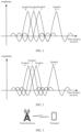
- FIG. 1 is a schematic diagram of a waveform of Nyquist signaling.
- a Nyquist signaling rate is an ultimate transmission rate of intersymbol interference-free transmission.
- the Nyquist signaling rate is equal to twice a bandwidth of a baseband signal; and for digital band-pass transmission, the Nyquist signaling rate is equal to a bandwidth of a band-pass signal.
- FIG. 2 is a schematic diagram of a waveform of FTN.
- a time-domain pulse interval may be compressed to increase symbol density, so that a transmission rate and spectral efficiency are improved, thereby implementing FTN.
- BPSK binary phase-shift keying
- a multi-carrier may be modulated through spectrally efficient frequency-division multiplexing (spectrally efficient frequency-division multiplexing, SEFDM) to ensure that a subcarrier width remains unchanged and a subcarrier spacing is compressed, thereby implementing multi-carrier FTN.
- SEFDM spectrally efficient frequency-division multiplexing
- intersymbol interference is introduced into FTN, and consequently, it is relatively difficult to demodulate an FTN signal.
- a Shannon channel capacity formula may be shown in Formula 1, and a free space path loss may be shown in Formula 2.
- C is the channel capacity
- B is a channel bandwidth
- n 0 is a noise power spectral density
- P r receive power
- P t transmit power
- C is a speed of light
- d is a propagation distance
- f c is a carrier frequency. If the receive power and the noise power spectral density are determinate, according to Formula 1 and Formula 2, a relationship between C and B may be further represented as Formula 3.
- C ⁇ B ⁇ log 2 P r n 0 B B ⁇ 0 P r n 0 ln 2 B ⁇ ⁇
- Table 1 frequency band LTE or NR Terahertz parameter carrier frequency is 3.5 GHz (gigahertz) receive power is 23 dBm (decibel-milliwatt) carrier frequency is 3000 GHz receive power is 23 dBm noise power spectral density is -102 dBm/MHz (decibel-milliwatt/megahertz) noise power spectral density is -72 dBm/GHz bandwidth 10 MHz 100 MHz Infinite 1 GHz 10 GHz Infinite channel capacity 59 Mbit/s (megabit/second) 280 Mbit/s 857 Mbit/s 266 Mbit/s 289 Mbit/s 292 Mbit/s gain none 375% 1353% None 8.65% 9.77%
- embodiments of the application provide the following technical solutions, to improve spectral efficiency of an ultra-high frequency band.
- the technical solutions in embodiments of the application may be applied to various communication systems, for example, a wireless fidelity (wireless fidelity, Wi-Fi) system, a vehicle-to-everything (vehicle-to-everything, V2X) communication system, a device-to-device (device-to-device, D2D) communication system, an Internet of Vehicles communication system, a 4th generation (4th generation, 4G) mobile communication system such as an LTE system, a 5th generation (5th generation, 5G) mobile communication system such as an NR system, and a future communication system such as a sixth generation (6th generation, 6G).
- a wireless fidelity wireless fidelity, Wi-Fi
- V2X vehicle-to-everything
- D2D device-to-device
- an Internet of Vehicles communication system a 4th generation (4th generation, 4G) mobile communication system such as an LTE system
- 5th generation (5th generation, 5G) mobile communication system such as an NR system
- the network architecture and the service scenario described in embodiments of the application are intended to describe the technical solutions in embodiments of the application more clearly, and do not constitute a limitation on the technical solutions provided in embodiments of the application.
- a person of ordinary skill in the art may know that, with evolution of the network architecture and emergence of new service scenarios, the technical solutions provided in embodiments of the application are also applicable to similar technical problems.
- FIG. 3 is a schematic diagram of an architecture of a communication system to which a communication method according to embodiments of the application is applicable.
- the communication system includes a terminal and a network device.
- the terminal is a terminal that accesses a network and that has a wireless receiving/sending function, or a chip or a chip system that can be disposed in the terminal.
- the terminal may also be referred to as user equipment (user equipment, UE), an access terminal, a subscriber unit (subscriber unit), a subscriber station, a mobile station (mobile station, MS), a remote station, a remote terminal, a mobile device, a user terminal, a terminal, a wireless communication device, a user agent, or a user apparatus.
- the terminal in the embodiment of the application may be a mobile phone (mobile phone), a cellular phone (cellular phone), a smartphone (smartphone), a tablet computer (Pad), a wireless data card, a personal digital assistant computer (personal digital assistant, PDA), a wireless modem (modem), a handset (handset), a laptop computer (laptop computer), a machine type communication (machine type communication, MTC) terminal, a computer with a wireless receiving/sending function, a virtual reality (virtual reality, VR) terminal, an augmented reality (augmented reality, AR) terminal, a wireless terminal in industrial control (industrial control), a wireless terminal in self driving (self driving), a wireless terminal in telemedicine or telehealth services (remote medical), a wireless terminal in a smart grid (smart grid), a wireless terminal in transportation safety (transportation safety), a wireless terminal in a smart city (smart city), a wireless terminal in a smart home (smart home), an in-vehicle terminal, an RSU with
- the terminal in the application may alternatively be an in-vehicle module, an in-vehicle assembly, an in-vehicle part, an in-vehicle chip, or an in-vehicle unit that is built in a vehicle as one or more parts or units.
- the network device for example, an access network device, is a device that is located on a network side of the communication system and that has a wireless receiving/sending function, or a chip or a chip system that can be disposed in the device.
- the network device may include an access network device in a next-generation mobile communication system such as 6G, for example, a gNB in 6G or a core network element in 6G.
- the network device may be named in other manners, which all fall within the protection scope of embodiments of the application. This is not limited in the application.
- the network device may alternatively include a gNB in 5G such as an NR system, or one antenna panel or a group of antenna panels (including a plurality of antenna panels) of a gNB in 5G; or may be a network node that forms a gNB, a transmission point (transmission and reception point, TRP, or transmission point, TP), or a transmission measurement function (transmission measurement function, TMF), for example, a baseband unit (BBU), a CU, a DU, a road side unit (road side unit, RSU) with a base station function, or a wired access gateway.
- a baseband unit BBU
- CU CU
- a DU road side unit
- RSU road side unit with a base station function
- wired access gateway a wired access gateway.
- the network device may alternatively include an access point (access point, AP), a wireless relay node, or a wireless backhaul node in a wireless fidelity (wireless fidelity, Wi-Fi) system, various forms of macro base stations, micro base stations (also referred to as small cells), relay stations, access points, wearable devices, in-vehicle devices, or the like.
- access point access point
- AP access point
- wireless relay node wireless backhaul node
- wireless backhaul node in a wireless fidelity (wireless fidelity, Wi-Fi) system
- various forms of macro base stations such as macro base stations, micro base stations (also referred to as small cells), relay stations, access points, wearable devices, in-vehicle devices, or the like.
- FIG. 4 is a first schematic flowchart of a communication method according to an embodiment of the application.
- the communication method is applicable to communication between a first device and a second device.
- the first device may be the terminal or the network device in the communication system shown in FIG. 3
- the second device may be the terminal or the network device in the communication system shown in FIG. 3 .
- the communication method includes S401, S402, and S403.
- the first device generates a first signal.
- the first signal is a signal obtained by performing deceleration modulation on a symbol.
- the first signal may be a single-carrier signal or a multi-carrier signal.
- Each symbol may be a modulation symbol corresponding to any one of the following adjustment manners: ⁇ /2-BPSK, on-off keying (on-off keying, OOK), amplitude-shift keying (amplitude-shift keying, ASK), quaternary phase-shift keying (quadrature phase-shift keying, QPSK), quadrature amplitude modulation (quadrature amplitude modulation, QAM), and the like, which is not limited; or may be a modulation symbol corresponding to any other possible modulation scheme.
- the deceleration modulation described above means increasing a time interval between symbols in a signal in a modulation process, that is, a time interval between two symbols that undergo deceleration modulation is greater than a time interval between the two symbols that do not undergo deceleration modulation, so that a transmission rate of the signal can be reduced.
- a signal transmission rate before deceleration modulation is a Nyquist signaling rate
- a signal transmission rate after deceleration modulation is less than the Nyquist signaling rate, and may also be referred to as a transmission rate of slower-than-Nyquist signaling (slower-than-Nyquist signaling, STN).
- a signal transmission rate after deceleration modulation is a Nyquist signaling rate or a slower-than-Nyquist signaling rate.
- a signal transmission rate before deceleration modulation is a slower-than-Nyquist signaling rate (denoted as an initial transmission rate of slower-than-Nyquist signaling)
- a signal transmission rate after deceleration modulation may be less than the initial transmission rate.
- the first signal is a single-carrier signal.
- the first signal may be a single-carrier signal obtained by performing deceleration modulation on a symbol based on single-carrier quadrature amplitude modulation (single-carrier quadrature amplitude modulation, SC-QAM).
- SC-QAM may be implemented based on a pulse shaping filter, that is, the first signal is also a signal obtained by performing deceleration modulation on the symbol based on the pulse shaping filter.
- s(t) is the first signal
- g(t) is an impulse response function of the pulse shaping filter
- a n is an n th symbol
- n is an integer ranging from - CP to N -1
- CP may be an integer
- CP is an index of a cyclic prefix.
- ⁇ n mod N means that a n takes the modulus of N .
- ⁇ may be defined as a deceleration factor (or any other possible name), and has a value greater than 1.
- the first device may flexibly adjust a symbol transmission rate of deceleration modulation by adjusting a value of ⁇ .
- deceleration modulation is represented by increasing a symbol time interval by two times; and if ⁇ is set to 3, deceleration modulation is represented by increasing the symbol time interval by three times, and so on.
- t is a time variable
- T is a time interval between two adjacent symbols (referred to as a time interval for short below).
- the pulse shaping filter is an ideal low-pass filter.
- the ideal low-pass filter may meet a Nyquist signaling rate, that is, a product of a time interval and a bandwidth of the ideal low-pass filter is 1/2.
- a waveform of the impulse response function of the ideal low-pass filter in time domain is a square wave.
- the bandwidth of the ideal low-pass filter and a frequency response of the ideal low-pass filter may meet a relationship shown in Formula 6.
- G ⁇ ⁇ 1 , ⁇ ⁇ 1 / 2 T 0 , ⁇ > 1 / 2 T
- f is a frequency of the ideal low-pass filter
- -B ⁇ f ⁇ B is the bandwidth of the ideal low-pass filter
- the pulse shaping filter is a square root raised cosine filter.
- the square root raised cosine filter usually cannot meet a Nyquist signaling rate, but can meet a slower-than-Nyquist signaling rate.
- a transmission rate of the square root raised cosine filter is 1/(1+ ⁇ ) of the Nyquist signaling rate, that is, a product of a time interval and a bandwidth of the square root raised cosine filter is (1+ ⁇ ) / 2, where ⁇ is a roll-off factor, and 0 ⁇ ⁇ ⁇ 1.
- An impulse response function of the square root raised cosine filter may be shown in Formula 7.
- g t sin ⁇ t 1 ⁇ ⁇ T + 4 ⁇ t T cos ⁇ t 1 + ⁇ T ⁇ t T 1 ⁇ 4 ⁇ t T 2
- f is a frequency of the square root raised cosine filter, -B ⁇ f ⁇ B, and B is the bandwidth of the square root raised cosine filter.
- the pulse shaping filter is a bandwidth-limited filter.
- the bandwidth-limited filter means that a bandwidth of the filter is a determinate value.
- the bandwidth-limited filter usually cannot meet a Nyquist signaling rate, but can meet a slower-than-Nyquist signaling rate, that is, a product of a time interval and the bandwidth of the bandwidth-limited filter is greater than 1/2.
- g ( t ) is an impulse response function of the bandwidth-limited filter, for example, a Gaussian function, and ⁇ is maximum intersymbol interference allowed by a system. It can be learned from Formula 9 that, for any two symbols modulated by the bandwidth-limited filter, a time interval between the two symbols can make intersymbol interference between the two symbols less than or equal to the maximum intersymbol interference allowed by the system, thereby avoiding affecting communication reliability due to an excessively high bit error rate.
- FIG. 5 is a schematic flowchart of SC-QAM.
- the first device may add a cyclic prefix to the first symbol sequence to obtain a second symbol sequence (the second symbol sequence includes the first symbol sequence and the cyclic prefix).
- the cyclic prefix may be at least some symbols in the first symbol sequence. For example, there are N symbols in the first symbol sequence, which are represented as [ a 0 ,a 1 ,..., a N -1 ], where N is an integer greater than 1.
- the cyclic prefix may be represented as [ a N-CP , a N-CP +1 ,.., a N -1 ].
- the second symbol sequence may be represented as [ a N-CP ,a N_CP +1 ,..., a N- 1 , a 0 , a 1 ,..., a N -1 ] .
- the first device may perform upsampling processing on the second symbol sequence to obtain a third symbol sequence that is more consecutive in time domain. Upsampling processing may be performing interpolation on the second symbol sequence, for example, inserting "0" between adjacent symbols. Therefore, upsampling processing is also referred to as interpolation processing.
- the second symbol sequence is represented as [ a N-CP ,a N-CP +1 ,..., a N- 1 , a 0 , a 1 ,..., a N -1 ] .
- the third symbol sequence obtained through upsampling processing may be represented as [ a N-CP ,0, a N-CP +1 ,0,..., a N- 1 ,0, a 0 ,0, a 1 ,0,..., a N -1 ] .
- the first device may perform shaping filtering on the third symbol sequence based on the pulse shaping filter, to increase a time interval between adjacent symbols in the third symbol sequence, so as to obtain the first signal shown in Formula 4.
- Case B The first signal is a multi-carrier signal.
- the first signal may be a multi-carrier signal obtained by performing deceleration modulation on a symbol based on multi-carrier orthogonal frequency-division multiplexing (orthogonal frequency-division multiplexing, OFDM) or single-carrier frequency-division multiple access (single-carrier frequency-division multiple access, SC-FDMA).
- SC-FDMA may be implemented based on extended Fourier transform (extended discrete Fourier transform), that is, the first signal is also a signal obtained by performing deceleration modulation on the symbol based on the extended Fourier transform.
- s(t) is the first signal
- K is a quantity of rows (that is, a quantity of subcarriers) in a matrix of the extended Fourier transform
- N is a quantity of columns in the matrix of the extended Fourier transform
- a n is an n th symbol
- e - j 2 ⁇ kf ( n ) is an element in the matrix of the extended Fourier transform
- ⁇ f is a subcarrier spacing
- f ( n ) is a variable (for a specific implementation principle, refer to the following related description)
- T cp is duration corresponding to a cyclic prefix in the first signal
- T sym is duration corresponding to an original signal in the first signal.
- a ratio of K to N may be considered as a deceleration factor of the multi-carrier signal, and the first device may flexibly adjust a symbol transmission rate of deceleration modulation by adjusting a value of the deceleration factor. For example, if the ratio of K to N is set to 2, deceleration modulation is represented by increasing a symbol time interval by two times; and if the ratio of K to N is set to 3, deceleration modulation is represented by increasing the symbol time interval by three times, and so on.
- the element in the matrix of the extended Fourier transform may be further represented as [ e - j 2 ⁇ kf ( n ) ] 0 ⁇ k ⁇ K -1,0 ⁇ n ⁇ N -1 .
- the first signal may be considered as a signal obtained by replicating, in frequency domain, the integer multiple of a sequence obtained by performing N- dimensional discrete Fourier transform (discrete fourier transform, DFT) on the symbol. Every two symbols in the first signal are equally spaced, and no intersymbol interference exists. For example, as shown in (a) in FIG. 6 , a symbol 0, a symbol 1, and a symbol 2 are equally spaced, and no intersymbol interference exists.
- the deceleration factor is a non-integer
- f(n) n / N in Formula 10
- the element in the matrix of the extended Fourier transform may be further represented as [ e - j 2 ⁇ kf ( n ) ] 0 ⁇ k ⁇ K -1,0 ⁇ n ⁇ N -1 .
- the first signal may be considered as a signal obtained by evenly mapping symbols to corresponding subcarriers. In this case, symbols in the first signal are equally spaced, but intersymbol interference may exist. As shown in (b) in FIG. 6 , a symbol 0, a symbol 1, and a symbol 2 are equally spaced, but intersymbol interference exists.
- the deceleration factor is a non-integer
- f ( n ) [ nK / N ] ' / K in formula 10, where [ ] ' is rounding (which is, for example, rounding up or rounding down, and is not limited in the application), and the element in the matrix of the extended Fourier transform may be further represented as [ e - j 2 ⁇ kf ( n ) ] 0 ⁇ k ⁇ K -1,0 ⁇ n ⁇ N -1 .
- the first signal may be considered as a signal obtained by unevenly mapping symbols to corresponding subcarriers. In this case, symbols in the first signal are not equally spaced, but no intersymbol interference exists. As shown in (c) in FIG. 6 , a symbol 0, a symbol 1, and a symbol 2 are not equally spaced, but no intersymbol interference exists.
- FIG. 7 is a schematic flowchart of SC-FDMA.
- the first device may perform extended Fourier transform on the first symbol sequence to obtain a fourth symbol sequence in frequency domain. For example, there are N symbols in the first symbol sequence, which are represented as [ a 0 , a 1 ,..., a N -1 ], where N is an integer greater than 1.
- the fourth symbol sequence may include K symbols, which are represented as [ b 0 ,b 1 ,..., b K- 1 ] .
- the first device may perform upsampling on the fourth symbol sequence to obtain a fifth symbol sequence. Upsampling processing may be performing interpolation on the fourth symbol sequence, for example, respectively inserting N FFT ⁇ K 2 "0" on two sides of the fourth symbol sequence.
- N FFT may be a quantity of points in fast Fourier transform, and usually has a value of an integer power of 2.
- the fourth symbol sequence is represented as [ b 0 , b 1 ,..., b K -1 ].
- the fifth symbol sequence obtained through upsampling processing may be represented as [0 ,..., 0, b 0 ,b 1 ,...,b K- 1 ,0,...,0] .
- the first device may perform inverse Fourier transform (inverse discrete Fourier transform, IDFT) on the fifth symbol sequence to obtain a sixth symbol sequence, which may be represented as [ c 0 , c 1 ,..., c N FFT -1 ].
- the first device may add a cyclic prefix to the sixth symbol sequence to obtain the first signal shown in Formula 10.
- the cyclic prefix may be at least some symbols in the sixth symbol sequence.
- the sixth symbol sequence is represented as [ c 0 , c 1 ,..., c N FFT -1 ].
- the cyclic prefix may be represented as [ C N FFT - N CP , c N FFT - N CP +1 ,..., c N FFT -1 ].
- the first signal may be represented in a sequence form, for example, represented as [ c N FFT - N CP , c N FFT - N CP +1 ,..., c N FFT -1 , c 0, c 1 ,..., c N FFT -1 ].
- S402 The first device sends the first signal.
- the second device receives the first signal.
- the first device may sequentially perform digital-to-analog conversion, up-conversion, and power amplification on the first signal, and then send the first signal.
- S403 The second device demodulates the first signal.
- the second device demodulates the first signal to obtain the symbol.
- FIG. 8 is a schematic flowchart of demodulation.
- the second device may perform band-pass filtering, downconversion, and analog-to-digital conversion on the first signal to obtain the first signal that is a digital signal.
- the second device may continue to perform matched filtering and downsampling on the first signal to obtain a symbol sequence that includes a cyclic prefix.
- the second device removes the cyclic prefix from the symbol sequence, and then performs equalization processing, for example, minimum mean square error equalization (optionally, maximal ratio combining processing may be further included) to obtain the symbol.
- equalization processing for example, minimum mean square error equalization (optionally, maximal ratio combining processing may be further included) to obtain the symbol.
- the second device may perform downsampling by using a slower-than-Nyquist signaling rate, or may perform downsampling by using a Nyquist signaling rate. This is not limited in the application.
- the first signal may alternatively be a signal obtained by performing deceleration and spectrum shifting modulation on the symbol based on the pulse shaping filter.
- deceleration modulation for example, unipolar deceleration modulation
- the first signal usually causes the first signal to have an impulse function (which is reflected as a peak characteristic on a spectrum).
- the symbol is a modulation symbol corresponding to OOK or unipolar ASK
- an impulse response function of the pulse shaping filter is g(t)
- a power spectral density function of the first signal may be shown in Formula 12.
- P s ( f ) is a power spectral density of the first signal
- f s is an element transmission rate of the first signal
- f s 1 / ⁇ T , that is, f s is negatively correlated with a symbol interval of the first signal
- a is a constant, and may be 1 to a positive infinity
- ⁇ ( f ) and ⁇ ( f -af s ) are impulse functions. It can be learned that a quantity of impulse functions is related to a value of f s . For example, a smaller f s indicates a larger deceleration amplitude of the first signal and a larger quantity of impulse functions of the first signal. For example, as shown in (a) in FIG.
- the signal has no impulse function, that is, a signal power spectral density shown in (a) in FIG. 8 has no peak.
- the signal has a small quantity of impulse functions, that is, a signal power spectral density shown in (b) in FIG. 8 has a small quantity of peaks.
- the signal has a small quantity of impulse functions, that is, a signal power spectral density shown in (b) in FIG. 8 has a small quantity of peaks.
- the signal has a large quantity of impulse functions, that is, a signal power spectral density shown in (c) in FIG. 8 has a large quantity of peaks.
- T g is pulse duration of the pulse shaping filter, and in the power spectral density function, a zero-crossing point interval of a side lobe of the first signal is a reciprocal of T g ; and 1 / 2 T g is a spectrum shifting amount, which may be further represented as Formula 13.
- g t ⁇ ⁇ nT cos ⁇ t ⁇ ⁇ nT / T g 1 2 g t ⁇ ⁇ nT e j ⁇ t ⁇ ⁇ nT / T g + 1 2 g t ⁇ ⁇ nT e ⁇ j ⁇ t ⁇ ⁇ nT / T g
- T g may be far greater than T , that is, a spectrum shifting amount of the first signal is relatively small, and is close to the zero-crossing point interval of the side lobe of the first signal.
- the first signal is shifted leftwards and rightwards by a half of the zero-crossing point interval, so that a side lobe of the first signal after spectrum shifting can be coherently superposed with the impulse function, to be suppressed or eliminated.
- the impulse function may be eliminated through spectrum shifting; or if the ratio of T g to T sym is a non-integer, the impulse function may be suppressed through spectrum shifting. For example, as shown in (d) in FIG. 8 , a signal is modulated through OOK and meets a slower-than-Nyquist signaling rate. If the ratio of T g to T sym is a non-integer, after spectrum shifting is performed on the signal, an impulse function on a side lobe of the signal is suppressed, that is, a height of a peak on the side lobe is decreased.
- a signal is modulated through OOK and meets a slower-than-Nyquist signaling rate. If the ratio of T g to T sym is an integer, after spectrum shifting is performed on the signal, an impulse function on a side lobe of the signal is eliminated, that is, there is no peak on the side lobe. In addition, because the spectrum shifting amount of the first signal is relatively small, a bandwidth increase of the first signal after spectrum shifting is very small, to ensure spectral efficiency.
- the spectrum shifting amount described above is merely an example, and constitutes no limitation.
- the first device may perform modulation by using a larger or smaller spectrum shifting amount. This is not limited in the embodiment of the application.
- a multi-carrier signal different signals correspond to different subcarriers, to implement frequency division multiplexing of different signals, so that a multiple access manner is more flexible and communication efficiency is higher.
- a first signal and a second signal are used as examples.
- the first device may perform extended Fourier transform on some symbols (denoted as a first symbol and represented as [ a 0,0 , a 1,0 ,...,a N- 1,0 ]) , map a transformed first symbol (represented as [ b 0,0 , b 1,0 ,..., b K -1,0 ]) to a first subcarrier, and perform upsampling and IDFT (for specific implementation, reference may be made to the foregoing related descriptions of the multi-carrier signal, and details are not described again), to obtain the first signal.
- some symbols denoted as a first symbol and represented as [ a 0,0 , a 1,0 ,...,a N- 1,0 ]
- map a transformed first symbol represented as [ b 0,0 , b 1,0 ,..., b K -1,0 ]
- upsampling and IDFT for specific implementation, reference may be made to the foregoing related descriptions of the multi-carrier signal, and details are not described again
- the first device may perform the extended Fourier transform on some other symbols (denoted as a second symbol and represented as [ a 0,1 , a 1,1 ,,..., a N -1,1 ]), map a transformed second symbol (represented as [ b 0,1 ,b 1,1+ ...,b K- 1,1 ]) to a second subcarrier, and perform upsampling and IDFT (for specific implementation, reference may be to the foregoing related descriptions of the multi-carrier signal, and details are not described again), to obtain the second signal.
- the first subcarrier is different from the second subcarrier.
- phase rotation amounts of different signals are different, that is, time division multiplexing of different signals is implemented by using sparseness of slower-than-Nyquist signaling in time domain, so that a multiple access manner is more flexible and communication efficiency is higher.
- a first signal and a second signal are used as examples.
- the first signal may be a signal obtained by performing deceleration modulation and phase rotation (for example, a phase rotation amount is ⁇ 1 ) modulation on some symbols (denoted as a first symbol) based on a matrix of extended Fourier transform
- the second signal may be a signal obtained by performing deceleration modulation and phase rotation (for example, a phase rotation amount is ⁇ 2 ) modulation on some other symbols (denoted as a second symbol) based on the matrix of the extended Fourier transform, where ⁇ 1 is different from ⁇ 2 .
- phase rotation amounts are different, the first signal and the second signal may be mapped to a same subcarrier.
- the first device may perform the extended Fourier transform on the first symbol (represented as [ a 0,0 , a 1,0 ,..., a N -1,0 ]), and perform phase rotation on a transformed first symbol (represented as [ b 0,0 ,b 1,0 ,..., b K- 1,0 ]) based on ⁇ 1 , to obtain a rotated first symbol (represented as [ c 0,0 , c 1,0 ,..., c K -1,0 ]).
- the first device maps the rotated first symbol to a third subcarrier, and performs upsampling and IDFT (for specific implementation, reference may be made to the foregoing related descriptions of the multi-carrier signal, and details are not described again), to obtain the first signal.
- the first device may perform the extended Fourier transform on the second symbol (represented as [ a 0,1 , a 1,1 ,...,a N- 1,1 ]), and perform phase rotation on a transformed second symbol (represented as [ b 0,1, b 1,1 ,..., b K -1,1 ]) based on ⁇ 2 , to obtain a rotated second symbol (represented as [ c 0,1 , c 1 ,1 ,..., c K -1,1 ]).
- the first device maps the rotated second symbol to the third subcarrier, and performs upsampling and IDFT (for specific implementation, reference may be made to the foregoing related descriptions of the multi-carrier signal, and details are not described again), to obtain the second signal.
- the first signal is used as an example.
- the first signal may be an m th signal in M signals, and a phase rotation amount of the first signal may meet a relationship shown in Formula 14: diag 1 , e ⁇ j 2 ⁇ m / MN , ... , e ⁇ j 2 ⁇ m K ⁇ 1 / MN
- K is the quantity of rows in the matrix of the extended Fourier transform
- N is the quantity of columns in the matrix of the extended Fourier transform.
- the first signal may include a plurality of pilot blocks (also referred to as a reference signal block, for example, a demodulation reference signal (demodulated reference signal, DMRS) block), phases of the plurality of pilot blocks are obtained through phase rotation, and phases of any two of the plurality of pilot blocks after rotation are different.
- a reference signal block for example, a demodulation reference signal (demodulated reference signal, DMRS) block
- DMRS demodulated reference signal
- the plurality of pilot blocks may be P pilot blocks, and a phase rotation amount of a p th pilot block in the P pilot blocks may meet a relationship shown in Formula 15. e ⁇ j ⁇ p p + 1 / P , 0 ⁇ p ⁇ P ⁇ 1 , and 1 ⁇ ⁇ ⁇ P ⁇ 1
- phases of the P pilot blocks after rotation are relatively randomly distributed on a complex number plane.
- multipath interference between the P pilot blocks may also be relatively randomly distributed on a unit circle to suppress each other, to reduce multipath interference between pilot blocks.
- the phases of the P pilot blocks after rotation may be relatively evenly distributed on the unit circle of the complex number plane. For example, as shown in FIG.
- a phase rotation amount of a pilot block 1 is e - j ⁇ 0 ⁇ 1/4
- a phase rotation amount of a pilot block 2 is e - j ⁇ 1 ⁇ 2/4
- a phase rotation amount of a pilot block 3 is e -j ⁇ 2 ⁇ 3/4
- a phase rotation amount of a pilot block 4 is e - j ⁇ 3 ⁇ 4/4 .
- multipath interference between the P pilot blocks may also be relatively evenly distributed on the unit circle to be superposed and canceled, to further reduce multipath interference between pilot blocks.
- Formula 15 is merely an example of determining a phase rotation amount of a pilot block, and constitutes no limitation.
- the first device may alternatively determine the phase rotation amount of the pilot block in any other possible manner, for example, randomly determining the phase rotation amount of the pilot block.
- FIG. 12 shows signal features of a signal 1 (a signal that undergoes 1/4 times of deceleration modulation, as shown by a dashed line) and a signal 2 (a signal that does not undergo 1/deceleration modulation, as shown by a solid line) in a non-line-of-sight (non-line-of-sight, NLOS) channel in an ultra-high frequency band.
- a signal 1 a signal that undergoes 1/4 times of deceleration modulation, as shown by a dashed line
- a signal 2 a signal that does not undergo 1/deceleration modulation, as shown by a solid line
- NLOS non-line-of-sight
- the signal 1 has a smaller signal-to-noise ratio, better transmission performance, and higher spectral efficiency; and if it is ensured that the signal 1 and the signal 2 have a same signal-to-noise ratio, the signal 1 has a smaller block error rate, better transmission performance, and higher spectral efficiency.
- Example 2 A signal pattern of a signal a is shown in (a) in FIG. 13 , where the signal a is a broadband signal and uses Nyquist signaling, and every eight symbols are used for equalization.
- a signal pattern of a signal b is shown in (b) in FIG. 13 , where the signal b is a narrowband signal and uses Nyquist signaling, and every four symbols are used for equalization.
- a signal pattern of a signal c is shown in (c) in FIG. 13 , where the signal c is a narrowband signal and uses Nyquist signaling, and every three symbols are used for equalization.
- a signal pattern of a signal d is shown in (d) in FIG.
- FIG. 13 where the signal d is a broadband signal and uses burst transmission, and every eight symbols are used for equalization.
- a signal pattern of a signal e is shown in (e) in FIG. 13 , where the signal e is a broadband signal and uses slower-than-Nyquist signaling with deceleration modulation, and every eight symbols are used for equalization.
- signal features of the signal a to the channel e may be shown in FIG. 14 . It can be learned from FIG.
- the signal e In a case of different bandwidths, that is, a broadband signal and a narrowband signal, if it is ensured that the signal b, the signal c, and the signal e have a same block error rate, the signal e also has a smaller signal-to-noise ratio, better transmission performance, and higher spectral efficiency; and if it is ensured that the signal b, the signal c, and the signal e have a same signal-to-noise ratio, the signal e also has a smaller block error rate, better transmission performance, and higher spectral efficiency.
- FIG. 15 is a first schematic diagram of a structure of a communication apparatus according to an embodiment of the application.
- the communication apparatus 1500 includes a transceiver module 1501 and a processing module 1502.
- FIG. 15 shows only main components of the communication apparatus.
- the communication apparatus 1500 may be used in the communication system shown in FIG. 3 , and performs a function of the first device in the method shown in FIG. 4 .
- the processing module 1502 is configured to generate a first signal, and the transceiver module 1501 is configured to send the first signal.
- the first signal is a signal obtained by performing deceleration modulation on a symbol, and a time interval between two symbols that undergo deceleration modulation is greater than a time interval between the two symbols that do not undergo deceleration modulation.
- the first signal may be a signal obtained by performing deceleration modulation on the symbol based on a pulse shaping filter.
- s(t) is the first signal
- g(t) is an impulse response function of the pulse shaping filter
- a n is an n th symbol
- n is an integer ranging from - CP to N -1
- CP is an index of a cyclic prefix
- CP may be an integer
- a value of ⁇ is greater than 1
- t is a time variable
- T is a time interval between two adjacent symbols.
- the first signal may be a signal obtained by performing deceleration and spectrum shifting modulation on the symbol based on the pulse shaping filter.
- s(t) is the first signal
- g(t) is an impulse response function of the pulse shaping filter
- a n is an n th symbol
- n is an integer ranging from - CP to N -1
- CP is an index of a cyclic prefix
- CP may be an integer
- a value of ⁇ is greater than 1
- t is a time variable
- T is a time interval between two adjacent symbols
- T g is pulse duration of the pulse shaping filter.
- the first signal may be a signal obtained by performing deceleration modulation on the symbol based on extended Fourier transform, a quantity of rows in a matrix of the extended Fourier transform is greater than a quantity of columns in the matrix of the extended Fourier transform, the quantity of columns in the matrix of the extended Fourier transform is the same as a quantity of symbols, and the quantity of rows in the matrix of the extended Fourier transform is the same as a quantity of subcarriers.
- s ( t ) is the first signal
- K is the quantity of rows in the matrix of the extended Fourier transform
- N is the quantity of columns in the matrix of the extended Fourier transform
- a n is an n th symbol
- e - j 2 ⁇ kf ( n ) is an element in the matrix of the extended Fourier transform
- [ ] ' rounding
- ⁇ f is a subcarrier spacing
- T cp duration corresponding to a cyclic prefix in the first signal
- T sym is duration corresponding to an original signal in the first signal.
- the first signal may be a signal obtained by performing deceleration modulation and phase rotation modulation on the symbol based on the matrix of the extended Fourier transform, and phase rotation amounts of different signals are different.
- the first signal may be an m th signal in M signals, and a phase rotation amount of the first signal may meet the following relationship: diag 1 , e ⁇ j 2 ⁇ m / MN , ... , e ⁇ j 2 ⁇ m K ⁇ 1 / MN .
- K is the quantity of rows in the matrix of the extended Fourier transform
- N is the quantity of columns in the matrix of the extended Fourier transform
- the first signal may include a plurality of pilot blocks, phases of the plurality of pilot blocks are obtained through phase rotation, and phases of any two of the plurality of pilot blocks after rotation are different.
- the plurality of pilot blocks may be P pilot blocks, and a phase rotation amount of a p th pilot block in the P pilot blocks may meet the following relationship: e ⁇ j ⁇ p p + 1 / P , 0 ⁇ p ⁇ P ⁇ 1 , and 1 ⁇ ⁇ ⁇ P ⁇ 1 .
- the transceiver module 1501 may also include a sending module and a receiving module (not shown in FIG. 15 ).
- the sending module is configured to implement a sending function of the communication apparatus 1500
- the receiving module is configured to implement a receiving function of the communication apparatus 1500.
- the communication apparatus 1500 may further include a storage module (not shown in FIG. 15 ), and the storage module stores a program or instructions.
- the processing module executes the program or the instructions, the communication apparatus 1500 is enabled to perform a function of the first device in the method shown in FIG. 4 .
- the processing module in the communication apparatus 1500 may be implemented by a processor or a processor-related circuit component, and may be a processor or a processing unit; and the transceiver module may be implemented by a transceiver or a transceiver-related circuit component, and may be a transceiver or a transceiver unit.
- the communication apparatus 1500 may be a terminal or a network device, may be a chip (system) or another part or component that can be disposed in a terminal or a network device, or may be an apparatus including a terminal or a network device. This is not limited in the application.
- the communication apparatus 1500 may be used in the communication system shown in FIG. 3 , and performs a function of the second device in the method shown in FIG. 4 .
- the transceiver module 1501 is configured to receive a first signal, and the processing module 1502 is configured to demodulate the first signal.
- the first signal is a signal obtained by performing deceleration modulation on a symbol, and a time interval between two symbols that undergo deceleration modulation is greater than a time interval between the two symbols that do not undergo deceleration modulation.
- the first signal may be a signal obtained by performing deceleration modulation on the symbol based on a pulse shaping filter.
- s(t) is the first signal
- g(t) is an impulse response function of the pulse shaping filter
- a n is an n th symbol
- n is an integer ranging from - CP to N -1
- CP is an index of a cyclic prefix
- CP may be an integer
- a value of ⁇ is greater than 1
- t is a time variable
- T is a time interval between two adjacent symbols.
- the first signal may be a signal obtained by performing deceleration and spectrum shifting modulation on the symbol based on the pulse shaping filter.
- s(t) is the first signal
- g(t) is an impulse response function of the pulse shaping filter
- a n is an n th symbol
- n is an integer ranging from - CP to N -1
- CP is an index of a cyclic prefix
- CP may be an integer
- a value of ⁇ is greater than 1
- t is a time variable
- T is a time interval between two adjacent symbols
- T g is pulse duration of the pulse shaping filter.
- the first signal may be a signal obtained by performing deceleration modulation on the symbol based on extended Fourier transform, a quantity of rows in a matrix of the extended Fourier transform is greater than a quantity of columns in the matrix of the extended Fourier transform, the quantity of columns in the matrix of the extended Fourier transform is the same as a quantity of symbols, and the quantity of rows in the matrix of the extended Fourier transform is the same as a quantity of subcarriers.
- s ( t ) is the first signal
- K is the quantity of rows in the matrix of the extended Fourier transform
- N is the quantity of columns in the matrix of the extended Fourier transform
- a n is an n th symbol
- e -j 2 ⁇ kf ( n ) is an element in the matrix of the extended Fourier transform
- [ ] ' is rounding
- ⁇ f is a subcarrier spacing
- T cp is duration corresponding to a cyclic prefix in the first signal
- T sym is duration corresponding to an original signal in the first signal.
- the first signal may be a signal obtained by performing deceleration modulation and phase rotation modulation on the symbol based on the matrix of the extended Fourier transform, and phase rotation amounts of different signals are different.
- the first signal may be an m th signal in M signals, and a phase rotation amount of the first signal may meet the following relationship: diag 1 , e ⁇ j 2 ⁇ m / MN , ... , e ⁇ j 2 ⁇ m K ⁇ 1 / MN .
- K is the quantity of rows in the matrix of the extended Fourier transform
- N is the quantity of columns in the matrix of the extended Fourier transform
- the first signal may include a plurality of pilot blocks, phases of the plurality of pilot blocks are obtained through phase rotation, and phases of any two of the plurality of pilot blocks after rotation are different.
- the plurality of pilot blocks may be P pilot blocks, and a phase rotation amount of a p th pilot block in the P pilot blocks may meet the following relationship: e ⁇ j ⁇ p p + 1 / P , 0 ⁇ p ⁇ P ⁇ 1 , and 1 ⁇ ⁇ ⁇ P ⁇ 1 .
- the transceiver module 1501 may also include a sending module and a receiving module (not shown in FIG. 15 ).
- the sending module is configured to implement a sending function of the communication apparatus 1500
- the receiving module is configured to implement a receiving function of the communication apparatus 1500.
- the communication apparatus 1500 may further include a storage module (not shown in FIG. 15 ), and the storage module stores a program or instructions.
- the processing module executes the program or the instructions, the communication apparatus 1500 is enabled to perform a function of the second device in the method shown in FIG. 4 .
- the processing module in the communication apparatus 1500 may be implemented by a processor or a processor-related circuit component, and may be a processor or a processing unit; and the transceiver module may be implemented by a transceiver or a transceiver-related circuit component, and may be a transceiver or a transceiver unit.
- the communication apparatus 1500 may be a terminal or a network device, may be a chip (system) or another part or component that can be disposed in a terminal or a network device, or may be an apparatus including a terminal or a network device. This is not limited in the application.
- FIG. 16 is a second schematic diagram of a structure of a communication apparatus according to an embodiment of the application.
- the communication apparatus may be a terminal device or a network device, or may be a chip (system) or another part of component that can be disposed in a terminal device or a network device.
- the communication apparatus 1600 may include a processor 1601.
- the communication apparatus 1600 may further include a memory 1602 and/or a transceiver 1603.
- the processor 1601 is coupled to the memory 1602 and the transceiver 1603, for example, may be connected by using a communication bus.
- the processor 1601 is a control center of the communication apparatus 1600, and may be a processor, may be a general name of a plurality of processing elements, or may be referred to as a logic circuit.
- the processor 1601 is one or more central processing units (central processing units, CPUs), or may be an application-specific integrated circuit (application-specific integrated circuit, ASIC), or one or more integrated circuits configured to implement embodiments of the application, for example, one or more microprocessors (digital signal processors, DSPs) or one or more field programmable gate arrays (field-programmable gate arrays, FPGAs).
- the processor 1601 may perform various functions of the communication apparatus 1600 by running or executing a software program stored in the memory 1602 and invoking data stored in the memory 1602.
- the processor 1601 may include one or more CPUs, for example, a CPU 0 and a CPU 1 shown in FIG. 16 .
- the communication apparatus 1600 may alternatively include a plurality of processors, for example, the processor 1601 and a processor 1604 shown in FIG. 16 .
- Each of the processors may be a single-core (single-CPU) processor or may be a multi-core (multi-CPU) processor.
- the processor herein may be one or more devices, circuits, and/or processing cores configured to process data (for example, computer program instructions).
- the memory 1602 is configured to store a software program for performing the solutions in the application, and the processor 1601 controls execution of the software program, so that the method shown in FIG. 4 is performed.
- the memory 1602 may be a read-only memory (read-only memory, ROM) or another type of static storage device that can store static information and instructions, or a random access memory (random access memory, RAM) or another type of dynamic storage device that can store information and instructions; or may be an electrically erasable programmable read-only memory (electrically erasable programmable read-only memory, EEPROM), a compact disc read-only memory (compact disc read-only memory, CD-ROM) or another optical disk storage, an optical disc storage (including a compact disc, a laser disc, an optical disc, a digital versatile disc, a Blu-ray disc, or the like), a magnetic disk storage medium or another magnetic storage device, or any other medium that can be configured to carry or store expected program code in a form of instructions or a data structure and that can be accessed by a computer.
- ROM read-only memory
- RAM random access memory
- EEPROM electrically erasable programmable read-only memory
- CD-ROM compact disc read-
- the memory 1602 may be integrated with the processor 1601, or may exist independently, and is coupled to the processor 1601 by using an interface circuit or an input/output interface (not shown in FIG. 16 ) of the communication apparatus 1600. This is not specifically limited in the embodiment of the application.
- the transceiver 1603 is configured to communicate with another communication apparatus.
- the communication apparatus 1600 is a terminal, and the transceiver 1603 may be configured to communicate with a network device or communicate with another terminal device.
- the communication apparatus 1600 is a network device, and the transceiver 1603 may be configured to communicate with a terminal or communicate with another network device.
- the transceiver 1603 may include a receiver and a transmitter (not separately shown in FIG. 16 ).
- the receiver is configured to implement a receiving function
- the transmitter is configured to implement a sending function.
- the transceiver 1603 may be integrated with the processor 1601, or may exist independently, and is coupled to the processor 1601 by using an interface circuit (not shown in FIG. 16 ) of the communication apparatus 1600. This is not specifically limited in the embodiment of the application.
- the structure of the communication apparatus 1600 shown in FIG. 16 does not constitute a limitation on the communication apparatus.
- An actual communication apparatus may include more or fewer parts than those shown in the figure, or combine some parts, or have different part arrangements.
- FIG. 17 is a third schematic diagram of a structure of a communication apparatus according to an embodiment of the application.
- the communication apparatus may be a terminal device or a network device, or may be a chip (system) or another part of component that can be disposed in a terminal device or a network device.
- the communication apparatus 1700 may include a logic circuit 1701 and an input/output interface 1702.
- the input/output interface 1702 is configured to receive code instructions and transmit the code instructions to the logic circuit 1701.
- the logic circuit 1701 is configured to run the code instructions to perform the method described above.
- An embodiment of the application provides a communication system.
- the communication system includes one or more of the foregoing terminals and one or more of the foregoing network devices.
- the processor in embodiments of the application may be a CPU, or the processor may be another general-purpose processor, a DSP, an ASIC, a field programmable gate array FPGA or another programmable logic device, a discrete gate or transistor logic device, a discrete hardware component, or the like.
- the general-purpose processor may be a microprocessor, or the processor may be any conventional processor or the like.
- the memory in embodiments of the application may be a volatile memory or a nonvolatile memory, or may include both a volatile memory and a nonvolatile memory.
- the nonvolatile memory may be a ROM, a programmable read-only memory (programmable ROM, PROM), an erasable programmable read-only memory (erasable PROM, EPROM), an EEPROM, or a flash memory.
- the volatile memory may be a RAM, and is used as an external cache.
- RAMs are available, for example, a static random access memory (static RAM, SRAM), a dynamic random access memory (DRAM), a synchronous dynamic random access memory (synchronous DRAM, SDRAM), a double data rate synchronous dynamic random access memory (double data rate SDRAM, DDR SDRAM), an enhanced synchronous dynamic random access memory (enhanced SDRAM, ESDRAM), a synchlink dynamic random access memory (synchlink DRAM, SLDRAM), and a direct rambus random access memory (direct rambus RAM, DR RAM).
- static random access memory static random access memory
- DRAM dynamic random access memory
- SDRAM synchronous dynamic random access memory
- double data rate SDRAM double data rate SDRAM
- DDR SDRAM double data rate SDRAM
- ESDRAM enhanced synchronous dynamic random access memory
- synchlink dynamic random access memory synchlink dynamic random access memory
- SLDRAM direct rambus random access memory
- direct rambus RAM direct rambus RAM
- All or some of the foregoing embodiments may be implemented by using software, hardware (for example, a circuit), firmware, or any other combination.
- the foregoing embodiments may be entirely or partially implemented in a form of a computer program product.
- the computer program product includes one or more computer instructions or computer programs. When the computer instructions or the computer programs or the instructions are loaded or executed on a computer, all or some of the procedures or functions according to embodiments of the application are generated.
- the computer may be a general-purpose computer, a dedicated computer, a computer network, or another programmable apparatus.
- the computer instructions may be stored in a computer-readable storage medium, or may be transmitted from one computer-readable storage medium to another computer-readable storage medium.
- the computer instructions may be transmitted from one website, computer, server, or data center to another website, computer, server, or data center in a wired (for example, infrared, radio, or microwave) manner.
- the computer-readable storage medium may be any available medium accessible to a computer, or a data storage device, such as a server or a data center, integrating one or more available media.
- the available medium may be a magnetic medium (for example, a floppy disk, a hard disk, or a magnetic tape), an optical medium (for example, a DVD), or a semiconductor medium.
- the semiconductor medium may be a solid-state drive.
- At least one means one or more, and "a plurality of” means two or more.
- At least one of the following items or a similar expression thereof means any combination of these items, including a singular item or any combination of plural items.
- at least one of a, b, or c may indicate a, b, c, a-b, a-c, b-c, or a-b-c, where a, b, and c may be singular or plural.
- sequence numbers of the foregoing processes do not mean execution sequences.
- the execution sequences of the processes should be determined by functions and internal logic of the processes, and shall not constitute any limitation on implementation processes of embodiments of the application.
- the disclosed system, apparatus, and method may be implemented in other manners.
- the apparatus embodiments described above are merely examples.
- division into the units is merely logical function division, and there may be another division manner in actual implementation.
- a plurality of units or components may be combined or integrated into another system, or some features may be ignored or not performed.
- the displayed or discussed mutual couplings or direct couplings or communication connections may be implemented by using some interfaces.
- the indirect couplings or communication connections between the apparatuses or the units may be implemented in an electrical form, a mechanical form, or another form.
- the units described as separate parts may or may not be physically separate, and parts displayed as units may or may not be physical units, that is, may be located in one place, or may be distributed on a plurality of network units. Some or all of the units may be selected based on actual requirements to achieve the objectives of the solutions of embodiments.
- the function When the function is implemented in a form of a software functional unit and sold or used as an independent product, the function may be stored in a computer-readable storage medium.
- the computer software product is stored in a storage medium and includes several instructions for instructing a computer device (which may be a personal computer, a server, a network device, or the like) to perform all or some of the steps of the methods in embodiments of the application.
- the foregoing storage medium includes any medium that can store program code, such as a USB flash drive, a removable hard disk, a ROM, a RAM, a magnetic disk, or an optical disc.
Landscapes
- Engineering & Computer Science (AREA)
- Computer Networks & Wireless Communication (AREA)
- Signal Processing (AREA)
- Physics & Mathematics (AREA)
- Spectroscopy & Molecular Physics (AREA)
- Power Engineering (AREA)
- Digital Transmission Methods That Use Modulated Carrier Waves (AREA)
- Transmitters (AREA)
- Mobile Radio Communication Systems (AREA)
Applications Claiming Priority (2)
| Application Number | Priority Date | Filing Date | Title |
|---|---|---|---|
| CN202111417858.4A CN116170270A (zh) | 2021-11-25 | 2021-11-25 | 通信方法及装置 |
| PCT/CN2022/134193 WO2023093821A1 (fr) | 2021-11-25 | 2022-11-24 | Procédé et appareil de communication |
Publications (2)
| Publication Number | Publication Date |
|---|---|
| EP4407941A1 true EP4407941A1 (fr) | 2024-07-31 |
| EP4407941A4 EP4407941A4 (fr) | 2025-01-22 |
Family
ID=86411895
Family Applications (1)
| Application Number | Title | Priority Date | Filing Date |
|---|---|---|---|
| EP22897904.3A Pending EP4407941A4 (fr) | 2021-11-25 | 2022-11-24 | Procédé et appareil de communication |
Country Status (4)
| Country | Link |
|---|---|
| US (1) | US20240323073A1 (fr) |
| EP (1) | EP4407941A4 (fr) |
| CN (1) | CN116170270A (fr) |
| WO (1) | WO2023093821A1 (fr) |
Families Citing this family (3)
| Publication number | Priority date | Publication date | Assignee | Title |
|---|---|---|---|---|
| WO2021004607A1 (fr) * | 2019-07-05 | 2021-01-14 | Telefonaktiebolaget Lm Ericsson (Publ) | Signal de réveil, et émetteur et récepteur correspondants |
| CN117278372B (zh) * | 2023-11-15 | 2024-06-25 | 荣耀终端有限公司 | 信号传输方法和通信设备 |
| CN120254860B (zh) * | 2025-06-03 | 2025-10-10 | 南方科技大学 | 超声测距方法、超声测距系统、存储介质及程序产品 |
Family Cites Families (9)
| Publication number | Priority date | Publication date | Assignee | Title |
|---|---|---|---|---|
| US6343101B1 (en) * | 1998-01-16 | 2002-01-29 | Ess Technology, Inc. | Frame-based sign inversion method and system for spectral shaping for pulse-coded-modulation modems |
| US6611567B1 (en) * | 1999-01-29 | 2003-08-26 | Agere Systems, Inc. | Method and apparatus for pulse shaping |
| WO2011052575A1 (fr) * | 2009-10-26 | 2011-05-05 | 住友電気工業株式会社 | Dispositif de communication sans fil |
| US8861588B2 (en) * | 2011-04-04 | 2014-10-14 | The United States Of America As Represented By The Secretary Of The Army | Apparatus and method for sampling and reconstruction of wide bandwidth signals below Nyquist rate |
| CN102571034B (zh) * | 2011-12-30 | 2015-04-22 | 北京邮电大学 | 基于随机循环矩阵的模拟压缩感知采样方法及系统 |
| US10038528B2 (en) * | 2014-12-19 | 2018-07-31 | Qualcomm Incorporated | Common reference signal design based on semi-uniform pilot spacing and orthogonal cover code |
| WO2017137068A1 (fr) * | 2016-02-09 | 2017-08-17 | Telefonaktiebolaget Lm Ericsson (Publ) | Procédé et dispositif pour former un signal sans fil |
| US10367600B2 (en) * | 2017-08-09 | 2019-07-30 | Ciena Corporation | Forward error correction with contrast coding |
| US11177995B2 (en) * | 2020-02-05 | 2021-11-16 | Huawei Technologies Co., Ltd. | Methods and apparatus for communicating a single carrier waveform |
-
2021
- 2021-11-25 CN CN202111417858.4A patent/CN116170270A/zh active Pending
-
2022
- 2022-11-24 WO PCT/CN2022/134193 patent/WO2023093821A1/fr not_active Ceased
- 2022-11-24 EP EP22897904.3A patent/EP4407941A4/fr active Pending
-
2024
- 2024-05-27 US US18/675,101 patent/US20240323073A1/en active Pending
Also Published As
| Publication number | Publication date |
|---|---|
| EP4407941A4 (fr) | 2025-01-22 |
| US20240323073A1 (en) | 2024-09-26 |
| CN116170270A (zh) | 2023-05-26 |
| WO2023093821A1 (fr) | 2023-06-01 |
Similar Documents
| Publication | Publication Date | Title |
|---|---|---|
| EP4407941A1 (fr) | Procédé et appareil de communication | |
| US11184131B2 (en) | Method and apparatus for transmitting reference signal | |
| JP6952785B2 (ja) | 情報送信方法および装置 | |
| WO2020238573A1 (fr) | Procédé et appareil de traitement de signaux | |
| EP4376369B1 (fr) | Procédé de traitement de signal basé sur une séquence et appareil de traitement de signal | |
| EP3913876A1 (fr) | Procédé et dispositif de transmission de données | |
| EP4436083A1 (fr) | Procédé et appareil de communication | |
| EP3937444B1 (fr) | Procédé et dispositif de compression de données | |
| WO2018059488A1 (fr) | Procédé et dispositif d'émission d'un signal de référence | |
| EP3595223B1 (fr) | Procédé et dispositif d'envoi d'un signal de référence de démodulation, et procédé et dispositif de démodulation | |
| US20250192943A1 (en) | Sequence-based signal processing method and apparatus | |
| EP4329361A1 (fr) | Procédé de transmission de symboles et appareil de communication | |
| WO2022082792A1 (fr) | Procédé et appareil de transmission de signal et de détection de signal | |
| EP4287545A1 (fr) | Procédé et dispositif de détermination d'un motif ptrs | |
| US10999108B2 (en) | Wireless communication method, apparatus, and system | |
| US20240414041A1 (en) | Signal transmission method and communication apparatus | |
| WO2022042618A1 (fr) | Procédé de transmission de signaux et appareil de communication | |
| EP4373044A1 (fr) | Procédé et appareil pour émettre un signal de référence de suivi de phase | |
| EP3907954B1 (fr) | Procédé et dispositif d'émission et de réception de signal | |
| CN116781468A (zh) | 一种通信方法及装置 | |
| CN117319157A (zh) | 数据处理方法和数据处理装置 | |
| US20260019311A1 (en) | Communication method and apparatus | |
| US20240171437A1 (en) | Signal transmission method and apparatus | |
| US20240380550A1 (en) | Data processing method and apparatus, and related device | |
| US20250294568A1 (en) | Method and apparatus for transmitting and receiving downlink channel and signal integrated with sensing |
Legal Events
| Date | Code | Title | Description |
|---|---|---|---|
| STAA | Information on the status of an ep patent application or granted ep patent |
Free format text: STATUS: THE INTERNATIONAL PUBLICATION HAS BEEN MADE |
|
| PUAI | Public reference made under article 153(3) epc to a published international application that has entered the european phase |
Free format text: ORIGINAL CODE: 0009012 |
|
| STAA | Information on the status of an ep patent application or granted ep patent |
Free format text: STATUS: REQUEST FOR EXAMINATION WAS MADE |
|
| 17P | Request for examination filed |
Effective date: 20240425 |
|
| AK | Designated contracting states |
Kind code of ref document: A1 Designated state(s): AL AT BE BG CH CY CZ DE DK EE ES FI FR GB GR HR HU IE IS IT LI LT LU LV MC ME MK MT NL NO PL PT RO RS SE SI SK SM TR |
|
| A4 | Supplementary search report drawn up and despatched |
Effective date: 20250103 |
|
| RIC1 | Information provided on ipc code assigned before grant |
Ipc: H04L 27/26 20060101ALI20241219BHEP Ipc: H04L 27/34 20060101AFI20241219BHEP |
|
| DAV | Request for validation of the european patent (deleted) | ||
| DAX | Request for extension of the european patent (deleted) |