EP4409966B1 - Indication du support du réseau de diverses fonctionnalités de liaison latérale (sl) - Google Patents
Indication du support du réseau de diverses fonctionnalités de liaison latérale (sl) Download PDFInfo
- Publication number
- EP4409966B1 EP4409966B1 EP22773611.3A EP22773611A EP4409966B1 EP 4409966 B1 EP4409966 B1 EP 4409966B1 EP 22773611 A EP22773611 A EP 22773611A EP 4409966 B1 EP4409966 B1 EP 4409966B1
- Authority
- EP
- European Patent Office
- Prior art keywords
- discovery
- relay
- ran node
- ues
- indication
- Prior art date
- Legal status (The legal status is an assumption and is not a legal conclusion. Google has not performed a legal analysis and makes no representation as to the accuracy of the status listed.)
- Active
Links
Images





Classifications
-
- H—ELECTRICITY
- H04—ELECTRIC COMMUNICATION TECHNIQUE
- H04W—WIRELESS COMMUNICATION NETWORKS
- H04W72/00—Local resource management
- H04W72/20—Control channels or signalling for resource management
- H04W72/25—Control channels or signalling for resource management between terminals via a wireless link, e.g. sidelink
-
- H—ELECTRICITY
- H04—ELECTRIC COMMUNICATION TECHNIQUE
- H04W—WIRELESS COMMUNICATION NETWORKS
- H04W48/00—Access restriction; Network selection; Access point selection
- H04W48/16—Discovering, processing access restriction or access information
-
- H—ELECTRICITY
- H04—ELECTRIC COMMUNICATION TECHNIQUE
- H04W—WIRELESS COMMUNICATION NETWORKS
- H04W8/00—Network data management
- H04W8/005—Discovery of network devices, e.g. terminals
-
- H—ELECTRICITY
- H04—ELECTRIC COMMUNICATION TECHNIQUE
- H04W—WIRELESS COMMUNICATION NETWORKS
- H04W48/00—Access restriction; Network selection; Access point selection
- H04W48/08—Access restriction or access information delivery, e.g. discovery data delivery
- H04W48/12—Access restriction or access information delivery, e.g. discovery data delivery using downlink control channel
-
- H—ELECTRICITY
- H04—ELECTRIC COMMUNICATION TECHNIQUE
- H04W—WIRELESS COMMUNICATION NETWORKS
- H04W88/00—Devices specially adapted for wireless communication networks, e.g. terminals, base stations or access point devices
- H04W88/02—Terminal devices
- H04W88/04—Terminal devices adapted for relaying to or from another terminal or user
-
- H—ELECTRICITY
- H04—ELECTRIC COMMUNICATION TECHNIQUE
- H04W—WIRELESS COMMUNICATION NETWORKS
- H04W92/00—Interfaces specially adapted for wireless communication networks
- H04W92/16—Interfaces between hierarchically similar devices
- H04W92/18—Interfaces between hierarchically similar devices between terminal devices
Definitions
- the present disclosure generally relates to wireless communication networks, and more specifically to user equipment (UE) that can communicate with other UEs directly rather than (or in addition to) indirect communication via a radio access network (RAN).
- UE user equipment
- RAN radio access network
- NR New Radio
- 3GPP Third-Generation Partnership Project
- eMBB enhanced mobile broadband
- MTC machine type communications
- URLLC ultra-reliable low latency communications
- D2D side-link device-to-device
- FIG. 1 illustrates an exemplary high-level view of the 5G network architecture, consisting of a Next Generation RAN (NG-RAN) 199 and a 5G Core (5GC) 198.
- NG-RAN 199 can include a set of gNodeB's (gNBs) connected to the 5GC via one or more NG interfaces, such as gNBs 100, 150 connected via interfaces 102, 152, respectively.
- the gNBs can be connected to each other via one or more Xn interfaces, such as Xn interface 140 between gNBs 100 and 150.
- each of the gNBs can support frequency division duplexing (FDD), time division duplexing (TDD), or a combination thereof.
- FDD frequency division duplexing
- TDD time division duplexing
- NG-RAN 199 is layered into a Radio Network Layer (RNL) and a Transport Network Layer (TNL).
- RNL Radio Network Layer
- TNL Transport Network Layer
- the NG-RAN architecture i.e., the NG-RAN logical nodes and interfaces between them, is defined as part of the RNL.
- NG, Xn, F1 For each NG-RAN interface (NG, Xn, F1) the related TNL protocol and the functionality are specified.
- the TNL provides services for user plane transport and signaling transport.
- the NG RAN logical nodes shown in Figure 1 include a central (or centralized) unit (CU or gNB-CU) and one or more distributed (or decentralized) units (DU or gNB-DU).
- gNB 100 includes gNB-CU 110 and gNB-DUs 120 and 130.
- CUs e . g ., gNB-CU 110
- CUs are logical nodes that host higher-layer protocols and perform various gNB functions such controlling the operation of DUs.
- Each DU is a logical node that hosts lower-layer protocols and can include, depending on the functional split, various subsets of the gNB functions.
- each of the CUs and DUs can include various circuitry needed to perform their respective functions, including processing circuitry, transceiver circuitry ( e . g ., for communication), and power supply circuitry.
- a gNB-CU connects to gNB-DUs over respective F1 logical interfaces, such as interfaces 122 and 132 shown in Figure 1 .
- the gNB-CU and connected gNB-DUs are only visible to other gNBs and the 5GC as a gNB. In other words, the F1 interface is not visible beyond gNB-CU.
- SL Sidelink
- D2D device-to-device
- ProSe proximity-based services
- 3GPP Rel-16 specifies the NR SL interface.
- NR Rel-16 SL targets advanced V2X services, which can be categorized into four use case groups: vehicles platooning, extended sensors, advanced driving, and remote driving.
- the advanced V2X services require a new SL in order to meet the stringent requirements in terms of latency and reliability.
- the NR SL is designed to provide higher system capacity and better coverage, and to allow for extension to support the future development of even more advanced V2X services and other related services.
- Broadcast, groupcast, and unicast transmissions are desirable for the services targeted by NR SL.
- groupcast or multicast
- the intended receiver of a message consists of only a subset of the possible recipients in proximity to the transmitter, whereas a unicast message is intended for only one recipient in proximity to the transmitter.
- groupcast or multicast
- the platooning service there are certain messages that are only of interest of the members of the platoon, for which groupcast can be used.
- Unicast is a natural fit for use cases involving only a pair of vehicles.
- 3GPP TR 23.752 (v2.0.0) section 6.7 describes Layer 2 (L2)-based U2N relay functionality, which includes forwarding functionality that can relay any type of traffic over the PC5 interface between two UEs.
- L2 U2N Relay UE supports connectivity to the 5GS (i.e., NG-RAN and 5GC) for other UEs that have successfully established a PC5 link to the L2 U2N Relay UE.
- a UE connected to a L2N relay will be seen by the network as a regular UE., as if it was directly connected to the network. This gives the network control of the connection and services, but requires the definition of several new mechanisms not present or needed in the L3 architecture.
- the MAC layer provides mapping between LCHs and PHY transport channels, LCH prioritization, multiplexing into or demultiplexing from transport blocks (TBs), hybrid ARQ (HARQ) error correction, and dynamic scheduling (on gNB side).
- the PHY layer provides transport channel services to the MAC layer and handles transfer over the NR radio interface, e.g., via modulation, coding, antenna mapping, and beam forming.
- DCI on PDCCH can include UL grants that indicate which UE is scheduled to transmit data on PUCCH in that slot, as well as which RBs will carry that data.
- a UE first detects and decodes DCI and, if the DCI includes an uplink grant for the UE, transmits the corresponding PUSCH on the resources indicated by the UL grant.
- DCI formats 0_0 and 0_1 are used to convey UL grants for PUSCH, while Other DCI formats (2_0, 2_1, 2_2 and 2_3) are used for other purposes including transmission of slot format information, reserved resource, transmit power control information, etc.
- the UE determines the Transport Block Size (TBS) for the PDSCH according to the procedure defined in 3GPP TS 38.214 V15.0.0 clause 5.1.3.2. Similar techniques can be used by the UE for PUSCH transmission scheduled by DCI (e.g., formats 0_0 or 0_1).
- DCI e.g., formats 0_0 or 0_1).
- UCI Uplink Control Information
- UEs transmit UCI (Uplink Control Information) UEs on the physical UL control channel (PUCCH).
- UCI can include HARQ feedback, CSI (Channel State Information) feedback, and SR (Scheduling Requests).
- CSI Channel State Information
- SR Service Requests
- NR supports two types of pre-configured resource assignments, both of which are similar to existing LTE semi-persistent scheduling (SPS) with some enhancements such as support for transport block (TB) repetitions.
- SPS semi-persistent scheduling
- UL data transmission with configured grant is only based on RRC (re)configuration without any L1 signaling.
- Type 2 is similar to the LTE SPS feature.
- UL data transmission with configured grant is based on both RRC configuration and layer-1 (L1) signaling for activation/deactivation of the grant.
- L1 layer-1
- a gNB needs to explicitly activate the configured resources on PDCCH and the UE confirms reception of the activation/deactivation grant using a MAC control element.
- a vehicle-to-everything (V2X) UE can support unicast communication via the uplink/downlink radio interface (also referred to as "Uu") to a 3GPP RAN, such as the LTE Evolved-UTRAN (E-UTRAN) or the NG-RAN.
- a V2X UE can also support SL unicast over the PC5 interface.
- Figure 5 shows an exemplary arrangement of interfaces between two V2X UEs and a RAN.
- the V2X UEs can communicate with a ProSe (PROximity-based SErvices) network function (NF) via respective PC3 interfaces.
- ProSe PROximity-based SErvices
- NF network function
- Figure 6 shows three exemplary network coverage scenarios for two UEs (610, 620) and a gNB (630) serving a cell (640).
- both UEs are in the coverage of the cell, such that they both can communicate with the gNB via respective Uu interfaces and directly with each other via the PC5 interface.
- the partial coverage scenario (center) only one of the UEs (i.e., 610) is in coverage of the cell, but the out-of-coverage UE (i.e., 620) can still communicate with the gNB indirectly via the PC5 interface with the in-coverage UE.
- both UEs can only communicate with each other via the PC5 interface.
- the term “SL standalone” refers to direct communication between two SL-capable UEs (e.g., via PC5) in which source and destination are the UEs themselves.
- the term “SL relay” refers to indirect communication between a network node and a remote UE via a first interface (e.g., Uu) between the network node an intermediate (or relay) UE and a second interface (e.g., PC5) between the relay UE and the remote UE. In this case the relay UE is neither the source nor the destination.
- an "out-of-coverage UE” is one that cannot establish a direct connection to the network and must communicate via either SL standalone or SL relay.
- a “peer UE” refers to a UE that can communicate with the out-of-coverage UE via SL standalone or SL relay (in which case the peer UE is also a relay UE).
- UEs that are in coverage can be configured (e.g., by a gNB) via RRC signaling and/or system information.
- Out-of-coverage UEs rely on a (pre-)configuration available in their SIMs. These pre-configurations are generally static but can be updated by the network when a UE is in coverage.
- NR SL radio resources are organized in REs, RBs, slots, and BWPs in a similar manner as UL/DL radio resources.
- SL supports transmission using 7-14 OFDM symbols, but any particular carrier is configured with only one transmission length at any time.
- SL radio resources also utilize sub-channels, which are collections of adjacent REs spanning an integer number of RBs in one transmission length (e.g., one slot).
- the sub-channel is the smallest unit that can be allocated for a normal SL transmission.
- Sub-channel size is (pre)configured.
- SL resources are also organized as resource pools, which are collections of sub-channels adjacent in frequency but not necessarily in time. A resource pool is (pre)configured.
- the Physical Sidelink Broadcast Channel (PSBCH) is transmitted along with the S-PSS/S-SSS as a synchronization signal/PSBCH block (SSB).
- the SSB has the same numerology as PSCCH/PSSCH on that carrier, and an SSB should be transmitted within the bandwidth of the configured BWP.
- the PSBCH conveys information related to synchronization, such as the direct frame number (DFN), indication of the slot and symbol level time resources for sidelink transmissions, in-coverage indicator, etc.
- the SSB is transmitted periodically every 160 ms.
- reference signals such as DMRS, PT-RS, CSI-RS, etc. that are supported on NR DL/UL are also supported on NR SL.
- PT-RS is only applicable for transmission in frequency range 2 (FR2) spectrum.
- NR SL supports two-part SCI.
- a first part of the SCI is sent on the PSCCH and can be read by all UEs.
- the second part of the SCI is sent on PSSCH and includes scheduling and control information such as an 8-bit source identity (ID), a 16-bit destination ID, new data indication (NDI), redundancy version (RV), and HARQ process ID.
- ID 8-bit source identity
- NDI new data indication
- RV redundancy version
- HARQ process ID HARQ process ID
- NR SL resource allocation mode 2 Two resource allocation modes are supported for NR SL transmissions between UEs.
- the resource allocation is performed by UE itself, e.g., autonomously based on sensing the carrier/resource pool for availability.
- the UE determines available resources by decoding sidelink control information (SCI) received from other UEs and/or energy sensing and selects a set of idle/available resources to use for its SL transmission. This can be done in a similar manner as described above in relation to DCI.
- SCI sidelink control information
- this transmitter UE When traffic arrives at a transmitter UE, this transmitter UE autonomously selects resources for the PSCCH and the PSSCH. To further minimize the latency of the feedback HARQ ACK/NACK transmissions and subsequent retransmissions, a transmitter UE may also reserve retransmission resources for PSCCH/PSSCH. To further enhance the probability of successful single-shot TB decoding and reduce retransmissions, a transmitter UE may repeat the TB transmission along with the initial TB transmission. This mechanism is also known as blind retransmission. As a result, when traffic arrives at a transmitter UE, then this transmitter UE should select resources for the following:
- a resource selection procedure based on channel sensing is used.
- the channel sensing involves measuring RSRP on different sub-channels and requires knowledge of the different UEs' power levels of DMRS on the PSSCH or on the PSCCH, depending on the configuration. This information is known only after receiving SCI from (all) other UEs.
- Resource reservation allows a UE to predict the utilization of the radio resources in the future. For example, a UE can obtain information about potential future transmissions by listening to the current transmissions of another UE. This information can be used by the UE to avoid collisions when selecting its own resources. As a more specific example, a UE predicts the future utilization of the radio resources by reading received booking messages and then schedules its transmissions to avoid using the same resources.
- NR SL resource allocation mode 1 all SL transmissions between UEs are scheduled by the network (e.g., a serving gNB) using a configured grant or a dynamic grant.
- a gNB can configure Mode 1 or Mode 2 for an in-coverage UE, but an out-of-coverage UE can only use Mode 2.
- Dynamic grants in Mode 1 are based on data being available for SL transmission, which triggers a buffer status report (BSR) by the UE having the data to send. If the UE already has an UL grant with enough resources, it will send the BSR to the gNB using these resources. Otherwise, it will trigger a SL scheduling request (SR) and send BSR on resources indicated by the UL grant in the responsive DCI from the gNB. After receiving the BSR, the gNB performs resource allocation and provides a SL grant to UE via downlink control information (DCI).
- DCI downlink control information
- a gNB may allocate a SL radio network temporary identifier (SL-RNTI) to the transmitter UE. If this sidelink resource request is granted by a gNB, then a gNB indicates the resource allocation for the PSCCH and the PSSCH in the downlink control information (DCI) conveyed by PDCCH with CRC scrambled with the SL-RNTI.
- DCI downlink control information
- a transmitter UE can obtain the grant only if the scrambled CRC of DCI can be successfully solved by the assigned SL-RNTI.
- a transmitter UE then indicates the time-frequency resources and the transmission scheme of the allocated PSSCH in the PSCCH, and launches the PSCCH and the PSSCH on the allocated resources for sidelink transmissions, and inserts a CRC in the SCI without any scrambling.
- a grant is obtained from a gNB, a transmitter UE can only transmit a single TB. As a result, this kind of grant is suitable for traffic with a loose latency requirement
- SR/BSR scheme for SL follows similar principles as the SR/BSR scheme for UL/DL (e.g., Uu interface).
- NR SL also supports configuration of multiple dedicated SL SRs. Each SR configuration can be mapped to one or more logical channels, so that the UE uses the specific SR configuration depending on the logical channel (as indicated by a logical channel ID, or LCID) associated with the data available in the SL buffer.
- the UE may also use SL BSR to indicate the amount of data available in the SL buffer.
- the UE will first send a SL SR and the network (e.g., gNB) will provide an UL grant for transmitting the BSR.
- the network e.g., gNB
- the network e.g., serving gNB
- RRC radio resource control
- Configured SL grants typically allocate resources having a periodic, semi-persistent pattern.
- Two types of configured SL grants are available, i.e., types 1 and 2.
- the network can activate/deactivate the RRC-configured grant using DCI signaling.
- the network may select the resources used for transmission but may give the transmitting SL UE some freedom to select some of the transmission parameters, possibly with some restrictions.
- a SL receiver UE In both dynamic and configured SL grant, a SL receiver UE cannot receive the DCI that is addressed to the transmitter UE. Thus, the receiver UE must perform blind decoding to identify the presence of PSCCH and find the resources for the PSSCH through the SCI.
- NR SL U2N relay uses two different architectures: a L3 architecture similar to LTE, and a newly defined architecture in which PC5 relaying occurs within Layer 2 (L2), over the RLC sublayer.
- L3-based U2N relay functionality is also referred to as ProSe 5G U2N Relay, and can be used for both public safety and commercial services.
- a UE connected to a L2 U2N relay is expected to be seen by the network as a regular UE, as if it was directly connected to the network. This gives the network control of the connection and services, but requires the definition of several new mechanisms not present or needed in the L3 architecture.
- FIG. 7 illustrates an exemplary user plane (UP) SL protocol stack for a protocol data unit (PDU) Session, including a L2 UE-to-Network Relay UE.
- the PDU layer carries data between the remote UE and the user plane function (UPF) in the 5GC, as part of the PDU session.
- the PDCP layer is terminated at the remote UE and the gNB, and the L2 relay function is below PDCP.
- the Adaptation Relay layer within the relay UE can differentiate between signaling radio bearers (SRBs) and data radio bearers (DRBs) for a particular remote UE.
- SRBs signaling radio bearers
- DRBs data radio bearers
- the Adaptation Relay layer is also responsible for mapping PC5 traffic to one or more DRBs of the Uu.
- 3GPP RAN WG2 is responsible for the definition of the Adaptation Relay layer.
- FIG 8 illustrates an exemplary control plane (CP) SL protocol stack for non-access stratum (NAS) messages, including a L2 UE-to-Network Relay UE.
- the NAS connection is between the remote UE and the AMF (for NAS-MM) and a session management function (SMF, for NAS-SM) in the 5GC.
- the NAS messages are transparently transferred between the remote UE and 5G-AN via the relay UE.
- the relay UE forwards SRB messages without any modification.
- the relay UE uses the same protocol stack for forwarding both CP messages and UP PDUs, as illustrated in Figures 7-8 .
- Figures 9-10 show an exemplary architecture model and an exemplary protocol stack, respectively, for L3 ProSe 5G U2N Relay, as further described in 3GPP TR 23.752 (v2.0.0).
- the ProSe 5G U2N Relay shall relay UL and DL unicast traffic between the Remote UE and the network (e.g., NG-RAN).
- One-to-one Direct Communication is used between Remote UEs and ProSe 5G U2N Relays for unicast traffic as specified in solutions for Key Issue #2 in 3GPP TR 23.752 (v2.0.0).
- the ProSe U2N Relay provides generic function that can relay any IP traffic. Hop-by-hop security is supported in the PC5 link and Uu link. If there are requirements beyond hop-by-hop security for protection of Remote UE's traffic, IP layer security should be applied.
- the host 1716 may be under the ownership or control of a service provider other than an operator or provider of the access network 1704 and/or the telecommunication network 1702, and may be operated by the service provider or on behalf of the service provider.
- the host 1716 may host a variety of applications to provide one or more service. Examples of such applications include live and pre-recorded audio/video content, data collection services such as retrieving and compiling data on various ambient conditions detected by a plurality of UEs, analytics functionality, social media, functions for controlling or otherwise interacting with remote devices, functions for an alarm and surveillance center, or any other such function performed by a server.
- the hub 1714 may be a data collector that acts as temporary storage for UE data and, in some embodiments, may perform analysis or other processing of the data.
- the hub 1714 may be a content source. For example, for a UE that is a VR headset, display, loudspeaker or other media delivery device, the hub 1714 may retrieve VR assets, video, audio, or other media or data related to sensory information via a network node, which the hub 1714 then provides to the UE either directly, after performing local processing, and/or after adding additional local content.
- the hub 1714 acts as a proxy server or orchestrator for the UEs, in particular in if one or more of the UEs are low energy IoT devices.
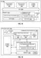
- the UE 1800 includes processing circuitry 1802 that is operatively coupled via a bus 1804 to an input/output interface 1806, a power source 1808, a memory 1810, a communication interface 1812, and/or any other component, or any combination thereof.
- Certain UEs may utilize all or a subset of the components shown in Figure 18 .
- the level of integration between the components may vary from one UE to another UE. Further, certain UEs may contain multiple instances of a component, such as multiple processors, memories, transceivers, transmitters, receivers, etc.
- the input/output interface 1806 may be configured to provide an interface or interfaces to an input device, output device, or one or more input and/or output devices.
- Examples of an output device include a speaker, a sound card, a video card, a display, a monitor, a printer, an actuator, an emitter, a smartcard, another output device, or any combination thereof.
- An input device may allow a user to capture information into the UE 1800.
- communication functions of the communication interface 1812 may include cellular communication, Wi-Fi communication, LPWAN communication, data communication, voice communication, multimedia communication, short-range communications such as Bluetooth, near-field communication, location-based communication such as the use of the global positioning system (GPS) to determine a location, another like communication function, or any combination thereof.
- GPS global positioning system
- Communications may be implemented in according to one or more communication protocols and/or standards, such as IEEE 802.11, Code Division Multiplexing Access (CDMA), Wideband Code Division Multiple Access (WCDMA), GSM, LTE, New Radio (NR), UMTS, WiMax, Ethernet, transmission control protocol/internet protocol (TCP/IP), synchronous optical networking (SONET), Asynchronous Transfer Mode (ATM), QUIC, Hypertext Transfer Protocol (HTTP), and so forth.
- CDMA Code Division Multiplexing Access
- WCDMA Wideband Code Division Multiple Access
- WCDMA Wideband Code Division Multiple Access
- GSM Global System for Mobile communications
- LTE Long Term Evolution
- NR New Radio
- UMTS Worldwide Interoperability for Microwave Access
- WiMax Ethernet
- TCP/IP transmission control protocol/internet protocol
- SONET synchronous optical networking
- ATM Asynchronous Transfer Mode
- QUIC Hypertext Transfer Protocol
- HTTP Hypertext Transfer Protocol
- a UE may provide an output of data captured by its sensors, through its communication interface 1812, via a wireless connection to a network node.
- Data captured by sensors of a UE can be communicated through a wireless connection to a network node via another UE.
- the output may be periodic (e.g., once every 15 minutes if it reports the sensed temperature), random (e.g., to even out the load from reporting from several sensors), in response to a triggering event (e.g., an alert is sent when moisture is detected), in response to a request (e.g., a user initiated request), or a continuous stream (e.g., a live video feed of a patient).
- a UE comprises an actuator, a motor, or a switch, related to a communication interface configured to receive wireless input from a network node via a wireless connection.
- the states of the actuator, the motor, or the switch may change.
- the UE may comprise a motor that adjusts the control surfaces or rotors of a drone in flight according to the received input or to a robotic arm performing a medical procedure according to the received input.
- a UE when in the form of an Internet of Things (IoT) device, may be a device for use in one or more application domains, these domains comprising, but not limited to, city wearable technology, extended industrial application and healthcare.
- IoT device are a device which is or which is embedded in: a connected refrigerator or freezer, a TV, a connected lighting device, an electricity meter, a robot vacuum cleaner, a voice controlled smart speaker, a home security camera, a motion detector, a thermostat, a smoke detector, a door/window sensor, a flood/moisture sensor, an electrical door lock, a connected doorbell, an air conditioning system like a heat pump, an autonomous vehicle, a surveillance system, a weather monitoring device, a vehicle parking monitoring device, an electric vehicle charging station, a smart watch, a fitness tracker, a head-mounted display for Augmented Reality (AR) or Virtual Reality (VR), a wearable for tactile augmentation or sensory enhancement, a water sprinkler, an animal- or item-
- AR Augmented
- a UE may represent a machine or other device that performs monitoring and/or measurements, and transmits the results of such monitoring and/or measurements to another UE and/or a network node.
- the UE may in this case be an M2M device, which may in a 3GPP context be referred to as an MTC device.
- the UE may implement the 3GPP NB-IoT standard.
- a UE may represent a vehicle, such as a car, a bus, a truck, a ship and an airplane, or other equipment that is capable of monitoring and/or reporting on its operational status or other functions associated with its operation.
- a first UE might be or be integrated in a drone and provide the drone's speed information (obtained through a speed sensor) to a second UE that is a remote controller operating the drone.
- the first UE may adjust the throttle on the drone (e.g., by controlling an actuator) to increase or decrease the drone's speed.
- the first and/or the second UE can also include more than one of the functionalities described above.
- a UE might comprise the sensor and the actuator, and handle communication of data for both the speed sensor and the actuators.
- Base stations may be categorized based on the amount of coverage they provide (or, stated differently, their transmit power level) and so, depending on the provided amount of coverage, may be referred to as femto base stations, pico base stations, micro base stations, or macro base stations.
- a base station may be a relay node or a relay donor node controlling a relay.
- a network node may also include one or more (or all) parts of a distributed radio base station such as centralized digital units and/or remote radio units (RRUs), sometimes referred to as Remote Radio Heads (RRHs). Such remote radio units may or may not be integrated with an antenna as an antenna integrated radio.
- RRUs remote radio units
- RRHs Remote Radio Heads
- Such remote radio units may or may not be integrated with an antenna as an antenna integrated radio.
- Parts of a distributed radio base station may also be referred to as nodes in a distributed antenna system (DAS).
- DAS distributed antenna system
- the network node 1900 includes a processing circuitry 1902, a memory 1904, a communication interface 1906, and a power source 1908.
- the network node 1900 may be composed of multiple physically separate components (e.g., a NodeB component and a RNC component, or a BTS component and a BSC component, etc.), which may each have their own respective components.
- the network node 1900 comprises multiple separate components (e.g., BTS and BSC components)
- one or more of the separate components may be shared among several network nodes.
- a single RNC may control multiple NodeBs.
- each unique NodeB and RNC pair may in some instances be considered a single separate network node.
- the network node 1900 may be configured to support multiple radio access technologies (RATs).
- RATs radio access technologies
- some components may be duplicated (e.g., separate memory 1904 for different RATs) and some components may be reused (e.g., a same antenna 1910 may be shared by different RATs).
- the network node 1900 may also include multiple sets of the various illustrated components for different wireless technologies integrated into network node 1900, for example GSM, WCDMA, LTE, NR, WiFi, Zigbee, Z-wave, LoRaWAN, Radio Frequency Identification (RFID) or Bluetooth wireless technologies. These wireless technologies may be integrated into the same or different chip or set of chips and other components within network node 1900.
- RFID Radio Frequency Identification
- the processing circuitry 1902 may comprise a combination of one or more of a microprocessor, controller, microcontroller, central processing unit, digital signal processor, application-specific integrated circuit, field programmable gate array, or any other suitable computing device, resource, or combination of hardware, software and/or encoded logic operable to provide, either alone or in conjunction with other network node 1900 components, such as the memory 1904, to provide network node 1900 functionality.
- the memory 1904 may comprise any form of volatile or non-volatile computer-readable memory including, without limitation, persistent storage, solid-state memory, remotely mounted memory, magnetic media, optical media, random access memory (RAM), read-only memory (ROM), mass storage media (for example, a hard disk), removable storage media (for example, a flash drive, a Compact Disk (CD) or a Digital Video Disk (DVD)), and/or any other volatile or non-volatile, non-transitory device-readable and/or computer-executable memory devices that store information, data, and/or instructions that may be used by the processing circuitry 1902.
- volatile or non-volatile computer-readable memory including, without limitation, persistent storage, solid-state memory, remotely mounted memory, magnetic media, optical media, random access memory (RAM), read-only memory (ROM), mass storage media (for example, a hard disk), removable storage media (for example, a flash drive, a Compact Disk (CD) or a Digital Video Disk (DVD)), and/or any other volatile or non-
- the memory 1904 may store any suitable instructions, data, or information, including a computer program, software, an application including one or more of logic, rules, code, tables, and/or other instructions (collectively denoted computer program product 1904a) capable of being executed by the processing circuitry 1902 and utilized by the network node 1900.
- the memory 1904 may be used to store any calculations made by the processing circuitry 1902 and/or any data received via the communication interface 1906.
- the processing circuitry 1902 and memory 1904 is integrated.
- the network node 1900 does not include separate radio front-end circuitry 1918, instead, the processing circuitry 1902 includes radio front-end circuitry and is connected to the antenna 1910.
- the processing circuitry 1902 includes radio front-end circuitry and is connected to the antenna 1910.
- all or some of the RF transceiver circuitry 1912 is part of the communication interface 1906.
- the communication interface 1906 includes one or more ports or terminals 1916, the radio front-end circuitry 1918, and the RF transceiver circuitry 1912, as part of a radio unit (not shown), and the communication interface 1906 communicates with the baseband processing circuitry 1914, which is part of a digital unit (not shown).
- the antenna 1910 may include one or more antennas, or antenna arrays, configured to send and/or receive wireless signals.
- the antenna 1910 may be coupled to the radio front-end circuitry 1918 and may be any type of antenna capable of transmitting and receiving data and/or signals wirelessly.
- the antenna 1910 is separate from the network node 1900 and connectable to the network node 1900 through an interface or port.
- the power source 1908 provides power to the various components of network node 1900 in a form suitable for the respective components (e.g., at a voltage and current level needed for each respective component).
- the power source 1908 may further comprise, or be coupled to, power management circuitry to supply the components of the network node 1900 with power for performing the functionality described herein.
- the network node 1900 may be connectable to an external power source (e.g., the power grid, an electricity outlet) via an input circuitry or interface such as an electrical cable, whereby the external power source supplies power to power circuitry of the power source 1908.
- the power source 1908 may comprise a source of power in the form of a battery or battery pack which is connected to, or integrated in, power circuitry. The battery may provide backup power should the external power source fail.
- Embodiments of the network node 1900 may include additional components beyond those shown in Figure 19 for providing certain aspects of the network node's functionality, including any of the functionality described herein and/or any functionality necessary to support the subject matter described herein.
- the network node 1900 may include user interface equipment to allow input of information into the network node 1900 and to allow output of information from the network node 1900. This may allow a user to perform diagnostic, maintenance, repair, and other administrative functions for the network node 1900.
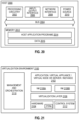
- FIG 20 is a block diagram of a host 2000, which may be an embodiment of the host 1716 of Figure 17 , in accordance with various aspects described herein.
- the host 2000 may be or comprise various combinations hardware and/or software, including a standalone server, a blade server, a cloud-implemented server, a distributed server, a virtual machine, container, or processing resources in a server farm.
- the host 2000 may provide one or more services to one or more UEs.
- the host 2000 includes processing circuitry 2002 that is operatively coupled via a bus 2004 to an input/output interface 2006, a network interface 2008, a power source 2010, and a memory 2012.
- Other components may be included in other embodiments. Features of these components may be substantially similar to those described with respect to the devices of previous figures, such as Figures 18 and 19 , such that the descriptions thereof are generally applicable to the corresponding components of host 2000.
- the memory 2012 may include one or more computer programs including one or more host application programs 2014 and data 2016, which may include user data, e.g., data generated by a UE for the host 2000 or data generated by the host 2000 for a UE.
- Embodiments of the host 2000 may utilize only a subset or all of the components shown.
- the host application programs 2014 may be implemented in a container-based architecture and may provide support for video codecs (e.g., Versatile Video Coding (VVC), High Efficiency Video Coding (HEVC), Advanced Video Coding (AVC), MPEG, VP9) and audio codecs (e.g., FLAC, Advanced Audio Coding (AAC), MPEG, G.711), including transcoding for multiple different classes, types, or implementations of UEs (e.g., handsets, desktop computers, wearable display systems, heads-up display systems).
- the host application programs 2014 may also provide for user authentication and licensing checks and may periodically report health, routes, and content availability to a central node, such as a device in or on the edge of a core network.
- the host 2000 may select and/or indicate a different host for over-the-top services for a UE.
- the host application programs 2014 may support various protocols, such as the HTTP Live Streaming (HLS) protocol, Real-Time Messaging Protocol (RTMP), Real-Time Streaming Protocol (RTSP), Dynamic Adaptive Streaming over HTTP (MPEG-DASH), etc.
- HTTP Live Streaming HLS
- RTMP Real-Time Messaging Protocol
- RTSP Real-Time Streaming Protocol
- MPEG-DASH Dynamic Adaptive Streaming over HTTP
- FIG. 21 is a block diagram illustrating a virtualization environment 2100 in which functions implemented by some embodiments may be virtualized.
- virtualizing means creating virtual versions of apparatuses or devices which may include virtualizing hardware platforms, storage devices and networking resources.
- virtualization can be applied to any device described herein, or components thereof, and relates to an implementation in which at least a portion of the functionality is implemented as one or more virtual components.
- Some or all of the functions described herein may be implemented as virtual components executed by one or more virtual machines (VMs) implemented in one or more virtual environments 2100 hosted by one or more of hardware nodes, such as a hardware computing device that operates as a network node, UE, core network node, or host.
- VMs virtual machines
- the virtual node does not require radio connectivity (e.g., a core network node or host)
- the node may be entirely virtualized.
- Applications 2102 (which may alternatively be called software instances, virtual appliances, network functions, virtual nodes, virtual network functions, etc.) are run in the virtualization environment 2100 to implement some of the features, functions, and/or benefits of some of the embodiments disclosed herein.
- Hardware 2104 includes processing circuitry, memory that stores software and/or instructions (collectively denoted computer program product 2104a) executable by hardware processing circuitry, and/or other hardware devices as described herein, such as a network interface, input/output interface, and so forth.
- Software may be executed by the processing circuitry to instantiate one or more virtualization layers 2106 (also referred to as hypervisors or virtual machine monitors (VMMs)), provide VMs 2108a and 2108b (one or more of which may be generally referred to as VMs 2108), and/or perform any of the functions, features and/or benefits described in relation with some embodiments described herein.
- the virtualization layer 2106 may present a virtual operating platform that appears like networking hardware to the VMs 2108.
- the VMs 2108 comprise virtual processing, virtual memory, virtual networking or interface and virtual storage, and may be run by a corresponding virtualization layer 2106.
- a virtualization layer 2106 Different embodiments of the instance of a virtual appliance 2102 may be implemented on one or more of VMs 2108, and the implementations may be made in different ways.
- Virtualization of the hardware is in some contexts referred to as network function virtualization (NFV).
- NFV network function virtualization
- NFV may be used to consolidate many network equipment types onto industry standard high volume server hardware, physical switches, and physical storage, which can be located in data centers, and customer premise equipment.
- a VM 2108 may be a software implementation of a physical machine that runs programs as if they were executing on a physical, non-virtualized machine.
- Each of the VMs 2108, and that part of hardware 2104 that executes that VM be it hardware dedicated to that VM and/or hardware shared by that VM with others of the VMs, forms separate virtual network elements.
- a virtual network function is responsible for handling specific network functions that run in one or more VMs 2108 on top of the hardware 2104 and corresponds to the application 2102.
- Hardware 2104 may be implemented in a standalone network node with generic or specific components. Hardware 2104 may implement some functions via virtualization. Alternatively, hardware 2104 may be part of a larger cluster of hardware (e.g., such as in a data center or CPE) where many hardware nodes work together and are managed via management and orchestration 2110, which, among others, oversees lifecycle management of applications 2102.
- hardware 2104 is coupled to one or more radio units that each include one or more transmitters and one or more receivers that may be coupled to one or more antennas. Radio units may communicate directly with other hardware nodes via one or more appropriate network interfaces and may be used in combination with the virtual components to provide a virtual node with radio capabilities, such as a radio access node or a base station.
- some signaling can be provided with the use of a control system 2112 which may alternatively be used for communication between hardware nodes and radio units.
- Figure 22 shows a communication diagram of a host 2202 communicating via a network node 2204 with a UE 2206 over a partially wireless connection in accordance with some embodiments.
- host 2202 Like host 2000, embodiments of host 2202 include hardware, such as a communication interface, processing circuitry, and memory.
- the host 2202 also includes software, which is stored in or accessible by the host 2202 and executable by the processing circuitry.
- the software includes a host application that may be operable to provide a service to a remote user, such as the UE 2206 connecting via an over-the-top (OTT) connection 2250 extending between the UE 2206 and host 2202.
- OTT over-the-top
- a host application may provide user data which is transmitted using the OTT connection 2250.
- the network node 2204 includes hardware enabling it to communicate with the host 2202 and UE 2206.
- the connection 2260 may be direct or pass through a core network (like core network 1706 of Figure 17 ) and/or one or more other intermediate networks, such as one or more public, private, or hosted networks.
- a core network like core network 1706 of Figure 17
- an intermediate network may be a backbone network or the Internet.
- the UE 2206 includes hardware and software, which is stored in or accessible by UE 2206 and executable by the UE's processing circuitry.
- the software includes a client application, such as a web browser or operator-specific "app" that may be operable to provide a service to a human or non-human user via UE 2206 with the support of the host 2202.
- a client application such as a web browser or operator-specific "app" that may be operable to provide a service to a human or non-human user via UE 2206 with the support of the host 2202.
- an executing host application may communicate with the executing client application via the OTT connection 2250 terminating at the UE 2206 and host 2202.
- the UE's client application may receive request data from the host's host application and provide user data in response to the request data.
- the OTT connection 2250 may transfer both the request data and the user data.
- the UE's client application may interact with the user to generate the user data that it provides to the host application through the OTT
- the OTT connection 2250 may extend via a connection 2260 between the host 2202 and the network node 2204 and via a wireless connection 2270 between the network node 2204 and the UE 2206 to provide the connection between the host 2202 and the UE 2206.
- the connection 2260 and wireless connection 2270, over which the OTT connection 2250 may be provided, have been drawn abstractly to illustrate the communication between the host 2202 and the UE 2206 via the network node 2204, without explicit reference to any intermediary devices and the precise routing of messages via these devices.
- the host 2202 provides user data, which may be performed by executing a host application.
- the user data is associated with a particular human user interacting with the UE 2206.
- the user data is associated with a UE 2206 that shares data with the host 2202 without explicit human interaction.
- the host 2202 initiates a transmission carrying the user data towards the UE 2206.
- the host 2202 may initiate the transmission responsive to a request transmitted by the UE 2206.
- the request may be caused by human interaction with the UE 2206 or by operation of the client application executing on the UE 2206.
- the transmission may pass via the network node 2204, in accordance with the teachings of the embodiments described throughout this disclosure. Accordingly, in step 2212, the network node 2204 transmits to the UE 2206 the user data that was carried in the transmission that the host 2202 initiated, in accordance with the teachings of the embodiments described throughout this disclosure. In step 2214, the UE 2206 receives the user data carried in the transmission, which may be performed by a client application executed on the UE 2206 associated with the host application executed by the host 2202.
- the UE 2206 executes a client application which provides user data to the host 2202.
- the user data may be provided in reaction or response to the data received from the host 2202.
- the UE 2206 may provide user data, which may be performed by executing the client application.
- the client application may further consider user input received from the user via an input/output interface of the UE 2206. Regardless of the specific manner in which the user data was provided, the UE 2206 initiates, in step 2218, transmission of the user data towards the host 2202 via the network node 2204.
- the term unit can have conventional meaning in the field of electronics, electrical devices and/or electronic devices and can include, for example, electrical and/or electronic circuitry, devices, modules, processors, memories, logic solid state and/or discrete devices, computer programs or instructions for carrying out respective tasks, procedures, computations, outputs, and/or displaying functions, and so on, as such as those that are described herein.
- Program code stored in memory includes program instructions for executing one or more telecommunications and/or data communications protocols as well as instructions for carrying out one or more of the techniques described herein.
- the processing circuitry may be used to cause the respective functional unit to perform corresponding functions according one or more embodiments of the present disclosure.
Landscapes
- Engineering & Computer Science (AREA)
- Computer Networks & Wireless Communication (AREA)
- Signal Processing (AREA)
- Computer Security & Cryptography (AREA)
- Databases & Information Systems (AREA)
- Mobile Radio Communication Systems (AREA)
Claims (22)
- Procédé pour un premier équipement utilisateur, UE, configuré pour un fonctionnement en liaison latérale, SL, dans une cellule d'un réseau d'accès radio, RAN, le procédé comprenant :
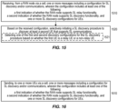
la réception (1510), en provenance d'un nœud RAN via la cellule, d'un ou plusieurs messages comprenant une configuration pour la découverte et/ou les communications SL, dans lequel la configuration comprend :une première indication indiquant si le nœud RAN prend en charge une fonctionnalité de relais SL ; unedeuxième indication indiquant si le nœud RAN prend en charge une fonctionnalité de découverte SL, dans lequel la deuxième indication comprend des premier et deuxième champs distincts, lorsqu'il est présent, le premier champ indique que le nœud RAN prend en charge la découverte de relais, correspondant aux fonctionnalités de découverte SL pour le relais SL ; etlorsqu'il est présent, le deuxième champ indique que le nœud RAN prend en charge la découverte sans relais, correspondant aux fonctionnalités de découverte SL pour des fins SL, mais pas pour le relais SL, ainsi qu'une ou plusieurs configurations de découverte SL pour les UE ; et,sur la base de la configuration, le lancement sélectif (1520) d'une procédure de découverte SL pour découvrir au moins un deuxième UE prenant en charge les communications SL. - Procédé selon la revendication 1, dans lequel l'absence de la première indication indique que le nœud RAN ne prend pas en charge la fonctionnalité de relais SL.
- Procédé selon la revendication 2, dans lequel, lorsqu'elle est présente, la première indication peut avoir une première valeur indiquant que le nœud RAN prend en charge le relais SL de couche 2.
- Procédé selon la revendication 3, dans lequel, lorsqu'elle est présente, la première indication peut également avoir l'une des valeurs suivantes : une deuxième valeur indiquant que le nœud RAN prend en charge le relais SL de couche 3, et une troisième valeur indiquant que le nœud RAN prend en charge les relais SL de couche 2 et 3.
- Procédé selon l'une quelconque des revendications 1 à 4, dans lequel les éléments suivants indiquent que le nœud RAN prend en charge la découverte sans relais, mais fournit des configurations de découverte SL à des UE :la deuxième indication étant présente et ayant un contenu indiquant que le nœud RAN prend en charge la découverte sans relais ; etl'absence de configurations de découverte SL à partir des un ou plusieurs messages.
- Procédé selon l'une quelconque des revendications 1 à 5, dans lequel :lorsqu'elles sont présentes dans les un ou plusieurs messages, les configurations de découverte SL comprennent une première configuration pour des UE relais et une deuxième configuration pour des UE non relais ; etle lancement sélectif (1520) de la procédure de découverte SL comprend la sélection (1521) de l'une des première et deuxième configurations pour la procédure de découverte SL, selon que le premier UE est un UE relais ou non relais.
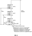
- Procédé selon la revendication 6, dans lequel chacune des première et deuxième configurations de découverte SL comprend un ou plusieurs des éléments suivants :une indication d'un ou plusieurs modèles de découverte pris en charge ;une fréquence à laquelle l'UE peut envoyer un message de découverte selon les modèles de découverte pris en charge ;un ou plusieurs seuils de qualité de canal radio pour le déclenchement de procédures de découverte ;un ou plusieurs seuils de qualité de canal radio pour la découverte d'un autre UE pendant une procédure de découverte ;des pools de ressources de découverte ; etdes bandes de fréquences ou porteuses sur lesquelles la découverte est prise en charge.
- Procédé selon l'une quelconque des revendications 1 à 7, dans lequel les un ou plusieurs messages sont reçus sous l'une des formes suivantes : un ou plusieurs blocs d'informations système, SIB, diffusés dans la cellule, ou un seul message de contrôle de ressources radio, RRC, en monodiffusion.
- Procédé permettant à un nœud de réseau d'accès radio, RAN, de configurer des équipements utilisateurs, UE, pour le fonctionnement en liaison latérale (SL), le procédé comprenant :
l'envoi (1610), à un ou plusieurs UE via une cellule, d'un ou plusieurs messages comprenant une configuration pour la découverte et/ou les communications SL, dans lequel la configuration comprend :une première indication indiquant si le nœud RAN prend en charge une fonctionnalité de relais SL ;une deuxième indication indiquant si le nœud RAN prend en charge une fonctionnalité de découverte SL, dans lequel le deuxième indication comprend des premier et deuxième champs distincts, lorsqu'il est présent, le premier champ indique que le nœud RAN prend en charge la découverte de relais, correspondant aux fonctionnalités de découverte SL pour le relais SL ; et, lorsqu'il est présent, le deuxième champ indique que le nœud RAN prend en charge la découverte sans relais, correspondant aux fonctionnalités de découverte SL pour des fins SL, mais pas pour le relais SL, et une ou plusieurs configurations de découverte SL pour des UE. - Procédé selon la revendication 9, dans lequel l'absence de la première indication indique que le nœud RAN ne prend pas en charge la fonctionnalité de relais SL.
- Procédé selon la revendication 10, dans lequel, lorsqu'elle est présente, la première indication peut avoir une première valeur indiquant que le nœud RAN prend en charge le relais SL de couche 2.
- Procédé selon la revendication 11, dans lequel, lorsqu'elle est présente, la première indication peut également avoir l'une des valeurs suivantes :une deuxième valeur indiquant que le nœud RAN prend en charge le relais SL de couche 3, etune troisième valeur indiquant que le nœud RAN prend en charge les relais SL de couche 2 et 3.
- Procédé selon l'une quelconque des revendications 9 à 12, dans lequel les éléments suivants indiquent que le nœud RAN prend en charge la découverte sans relais, mais fournit des configurations de découverte SL à des UE :la deuxième indication étant présente et ayant un contenu indiquant que le nœud RAN prend en charge la découverte sans relais ; etl'absence de configurations de découverte SL à partir des un ou plusieurs messages.
- Procédé selon l'une quelconque des revendications 9 à 13, dans lequel, lorsqu'elles sont présentes dans les un ou plusieurs messages, les une ou plusieurs configurations de découverte SL comprennent une première configuration de découverte pour des UE relais et une deuxième configuration de découverte pour des UE non relais.
- Procédé selon la revendication 14, dans lequel chacune des première et deuxième configurations de découverte SL comprend un ou plusieurs des éléments suivantsune indication d'un ou plusieurs modèles de découverte pris en charge ;la fréquence à laquelle l'UE peut envoyer un message de découverte selon les modèles de découverte pris en charge ;un ou plusieurs seuils de qualité de canal radio pour le déclenchement des procédures de découverte ;un ou plusieurs seuils de qualité de canal radio pour la découverte d'un autre UE pendant une procédure de découverte ; des pools de ressources de découverte ; etdes bandes de fréquences ou porteuses sur lesquelles la découverte est prise en charge.
- Procédé selon l'une quelconque des revendications 9 à 15, dans lequel les un ou plusieurs messages sont envoyés sous l'une des formes suivantes : un ou plusieurs blocs d'informations système, SIB, diffusés dans la cellule ; ou un ou plusieurs messages de contrôle de ressources radio, RRC, en monodiffusion aux un ou plusieurs UE respectifs.
- Premier équipement utilisateur, UE, (210, 610, 620, 1712, 1800, 2206) configuré pour fonctionner en liaison latérale, SL, dans une cellule d'un réseau d'accès radio, RAN, (199, 1704), le premier UE étant en outre configuré pour :
recevoir, d'un nœud RAN (100, 150, 220, 630, 1710, 1900, 2102, 2204) via la cellule, un ou plusieurs messages comprenant une configuration pour la découverte et/ou les communications SL, dans lequel la configuration comprend :une première indication indiquant si le nœud RAN prend en charge la fonctionnalité de relais SL ;une deuxième indication indiquant si le nœud RAN prend en charge une fonctionnalité de découverte SL, dans lequel la deuxième indication comprend des premier et deuxième champs distincts, lorsqu'il est présent, le premier champ indique que le nœud RAN prend en charge la découverte de relais, correspondant aux fonctionnalités de découverte SL pour le relais SL, et, lorsqu'il est présent, le deuxième champ indique que le nœud RAN prend en charge la découverte sans relais, correspondant aux fonctionnalités de découverte SL pour les communications SL, mais pas pour le relais SL, et une ou plusieurs configurations de découverte SL pour les UE ; et,sur la base de la configuration, lancer sélectivement une procédure de découverte SL pour découvrir au moins un deuxième UE prenant en charge les communications SL. - Premier UE selon la revendication 17, étant en outre configuré pour effectuer des opérations correspondant à l'un quelconque des procédés des revendications 2 à 8.
- Produit de programme informatique (1814) comprenant des instructions exécutables par ordinateur qui, lorsqu'elles sont exécutées par un circuit de traitement (1802) d'un premier équipement utilisateur, UE, (210, 610, 620, 1712, 1800, 2206) configuré pour un fonctionnement en liaison latérale, SL, dans une cellule d'un réseau d'accès radio, RAN, (199, 1704), configurent le premier UE pour effectuer des opérations correspondant à l'un quelconque des procédés selon les revendications 1 à 8.
- Nœud de réseau d'accès radio, RAN, (100, 150, 220, 630, 1710, 1900, 2102, 2204) conçu pour configurer des équipements utilisateurs, UE, (210, 610, 620, 1712, 1800, 2206) pour un fonctionnement en liaison latérale, SL, le nœud RAN étant également conçu pour :
envoyer, via une cellule, à un ou plusieurs UE, un ou plusieurs messages comprenant une configuration pour la découverte et/ou les communications SL, dans lequel la configuration comprend :une première indication indiquant si le nœud RAN prend en charge la fonctionnalité de relais SL ;une deuxième indication indiquant si le nœud RAN prend en charge la fonctionnalité de découverte SL, dans lequel la deuxième indication comprend des premier et deuxième champs distincts, lorsqu'il est présent, le premier champ indique que le nœud RAN prend en charge la découverte de relais, correspondant aux fonctionnalités de découverte SL pour le relais SL, et, lorsqu'il est présent, le deuxième champ indique que le nœud RAN prend en charge la découverte sans relais, correspondant aux fonctionnalités de découverte SL pour des fins SL, mais pas pour le relais SL, etune ou plusieurs configurations de découverte SL pour les UE. - Nœud RAN selon la revendication 20, configuré en outre pour effectuer des opérations correspondant à l'un quelconque des procédés selon les revendications 10 à 16.
- Produit de programme informatique (1904a, 2104a) comprenant des instructions exécutables par ordinateur qui, lorsqu'elles sont exécutées par un circuit de traitement (1902, 2104) d'un nœud (100, 150, 220, 630, 1710, 1900, 2102, 2204) de réseau d'accès radio, RAN, conçu pour configurer des équipements utilisateurs, UE, (210, 610, 620, 1712, 1800, 2206) pour le fonctionnement en liaison latérale, SL, configurent le nœud RAN pour effectuer des opérations correspondant à l'un quelconque des procédés selon revendications 9 à 16.
Priority Applications (1)
| Application Number | Priority Date | Filing Date | Title |
|---|---|---|---|
| EP25183704.3A EP4633289A3 (fr) | 2021-09-30 | 2022-09-05 | Indication de prise en charge de réseau de diverses fonctionnalités de liaison latérale (sl) |
Applications Claiming Priority (2)
| Application Number | Priority Date | Filing Date | Title |
|---|---|---|---|
| US202163250833P | 2021-09-30 | 2021-09-30 | |
| PCT/EP2022/074628 WO2023052049A1 (fr) | 2021-09-30 | 2022-09-05 | Indication de prise en charge de réseau de diverses fonctionnalités de liaison latérale (sl) |
Related Child Applications (1)
| Application Number | Title | Priority Date | Filing Date |
|---|---|---|---|
| EP25183704.3A Division EP4633289A3 (fr) | 2021-09-30 | 2022-09-05 | Indication de prise en charge de réseau de diverses fonctionnalités de liaison latérale (sl) |
Publications (3)
| Publication Number | Publication Date |
|---|---|
| EP4409966A1 EP4409966A1 (fr) | 2024-08-07 |
| EP4409966B1 true EP4409966B1 (fr) | 2025-06-25 |
| EP4409966C0 EP4409966C0 (fr) | 2025-06-25 |
Family
ID=83400633
Family Applications (2)
| Application Number | Title | Priority Date | Filing Date |
|---|---|---|---|
| EP22773611.3A Active EP4409966B1 (fr) | 2021-09-30 | 2022-09-05 | Indication du support du réseau de diverses fonctionnalités de liaison latérale (sl) |
| EP25183704.3A Pending EP4633289A3 (fr) | 2021-09-30 | 2022-09-05 | Indication de prise en charge de réseau de diverses fonctionnalités de liaison latérale (sl) |
Family Applications After (1)
| Application Number | Title | Priority Date | Filing Date |
|---|---|---|---|
| EP25183704.3A Pending EP4633289A3 (fr) | 2021-09-30 | 2022-09-05 | Indication de prise en charge de réseau de diverses fonctionnalités de liaison latérale (sl) |
Country Status (4)
| Country | Link |
|---|---|
| US (1) | US20250133576A1 (fr) |
| EP (2) | EP4409966B1 (fr) |
| CN (2) | CN118044270A (fr) |
| WO (1) | WO2023052049A1 (fr) |
Families Citing this family (4)
| Publication number | Priority date | Publication date | Assignee | Title |
|---|---|---|---|---|
| WO2024211628A1 (fr) * | 2023-04-04 | 2024-10-10 | Ofinno, Llc | Extension de préfixe cyclique dans un fonctionnement de liaison latérale |
| CN119383545A (zh) * | 2023-07-26 | 2025-01-28 | 大唐移动通信设备有限公司 | 信息传输方法及装置 |
| CN119521174A (zh) * | 2023-08-11 | 2025-02-25 | 华为技术有限公司 | 通信方法和装置 |
| WO2025038014A1 (fr) * | 2023-08-15 | 2025-02-20 | Telefonaktiebolaget Lm Ericsson (Publ) | Déclenchement d'une procédure de recherche dans l'ido |
Family Cites Families (1)
| Publication number | Priority date | Publication date | Assignee | Title |
|---|---|---|---|---|
| WO2021097801A1 (fr) * | 2019-11-22 | 2021-05-27 | Mediatek Singapore Pte. Ltd. | Procédés et appareil de routage de paquet pour un relais de liaison latérale |
-
2022
- 2022-09-05 CN CN202280066272.4A patent/CN118044270A/zh active Pending
- 2022-09-05 WO PCT/EP2022/074628 patent/WO2023052049A1/fr not_active Ceased
- 2022-09-05 EP EP22773611.3A patent/EP4409966B1/fr active Active
- 2022-09-05 US US18/693,386 patent/US20250133576A1/en active Pending
- 2022-09-05 EP EP25183704.3A patent/EP4633289A3/fr active Pending
- 2022-09-05 CN CN202410686497.0A patent/CN118488528A/zh active Pending
Also Published As
| Publication number | Publication date |
|---|---|
| WO2023052049A1 (fr) | 2023-04-06 |
| US20250133576A1 (en) | 2025-04-24 |
| CN118044270A (zh) | 2024-05-14 |
| EP4633289A3 (fr) | 2025-12-24 |
| EP4409966A1 (fr) | 2024-08-07 |
| EP4633289A2 (fr) | 2025-10-15 |
| EP4409966C0 (fr) | 2025-06-25 |
| CN118488528A (zh) | 2024-08-13 |
Similar Documents
| Publication | Publication Date | Title |
|---|---|---|
| EP4409966B1 (fr) | Indication du support du réseau de diverses fonctionnalités de liaison latérale (sl) | |
| WO2023117873A1 (fr) | Identification de terminal pour communication à l'aide d'un dispositif terminal relais | |
| US20260121732A1 (en) | Beam Failure Detection and Recovery for Deactivated Secondary Cell Group (SCG) | |
| WO2023209668A1 (fr) | Signalisation et mécanismes pour scénarios de liaison latérale à sauts multiples de transmission de message de découverte d'ue relais | |
| WO2023166498A1 (fr) | Systèmes et procédés d'association implicite entre une transmission pusch à trp multiples et des états tci unifiés | |
| US20250185029A1 (en) | Sidelink Communication using Shared Channel Occupancy in Unlicensed Spectrum | |
| US20260106784A1 (en) | Demodulation Reference Signal (DMRS) Port Association for Simultaneous Multi-Panel Transmission User Equipment | |
| US20260059423A1 (en) | Power efficient transmission and scheduling of cooperative devices in the uplink | |
| US20250185121A1 (en) | Handling of Establishment Causes in Sidelink Relay Scenarios | |
| US20250392422A1 (en) | Modification of periodic multi-slot allocations | |
| EP4490871A1 (fr) | États de tci unifiés pour pdsch à multiples trp | |
| EP4548645A1 (fr) | Procédé et appareil pour permettre un relais pour un ue distant au moyen d'une liaison terrestre idéale | |
| US20240314789A1 (en) | Dynamically reconfigurable uplink resources | |
| KR20240006070A (ko) | Pucch 캐리어 스위칭을 위한 반정적 패턴 구성을 위한 장치 및 방법 | |
| TWI827287B (zh) | 基於混合arq考量之控制通道監控 | |
| EP4410045B1 (fr) | Détection contiguë étendue lors d'une réception discontinue de liaison latérale (sl-drx) | |
| WO2023148335A1 (fr) | Configurabilité améliorée pour planification semi-persistante et autorisations configurées | |
| WO2024172747A1 (fr) | Signalisation d'occasions de transmission d'autorisation configurées inutilisées | |
| EP4666774A1 (fr) | Génération de pdu mac pour de multiples occasions de transmission d'autorisations configurées | |
| WO2023217659A1 (fr) | Communication de liaison latérale entrelacée | |
| WO2024181902A1 (fr) | Mobilité double pour transmissions coopératives |
Legal Events
| Date | Code | Title | Description |
|---|---|---|---|
| STAA | Information on the status of an ep patent application or granted ep patent |
Free format text: STATUS: UNKNOWN |
|
| STAA | Information on the status of an ep patent application or granted ep patent |
Free format text: STATUS: THE INTERNATIONAL PUBLICATION HAS BEEN MADE |
|
| PUAI | Public reference made under article 153(3) epc to a published international application that has entered the european phase |
Free format text: ORIGINAL CODE: 0009012 |
|
| STAA | Information on the status of an ep patent application or granted ep patent |
Free format text: STATUS: REQUEST FOR EXAMINATION WAS MADE |
|
| 17P | Request for examination filed |
Effective date: 20240426 |
|
| AK | Designated contracting states |
Kind code of ref document: A1 Designated state(s): AL AT BE BG CH CY CZ DE DK EE ES FI FR GB GR HR HU IE IS IT LI LT LU LV MC MK MT NL NO PL PT RO RS SE SI SK SM TR |
|
| GRAP | Despatch of communication of intention to grant a patent |
Free format text: ORIGINAL CODE: EPIDOSNIGR1 |
|
| STAA | Information on the status of an ep patent application or granted ep patent |
Free format text: STATUS: GRANT OF PATENT IS INTENDED |
|
| RIC1 | Information provided on ipc code assigned before grant |
Ipc: H04W 92/18 20090101ALN20240903BHEP Ipc: H04W 88/04 20090101ALN20240903BHEP Ipc: H04W 48/12 20090101ALN20240903BHEP Ipc: H04W 8/00 20090101ALN20240903BHEP Ipc: H04W 48/16 20090101AFI20240903BHEP |
|
| DAV | Request for validation of the european patent (deleted) | ||
| DAX | Request for extension of the european patent (deleted) | ||
| INTG | Intention to grant announced |
Effective date: 20240913 |
|
| GRAJ | Information related to disapproval of communication of intention to grant by the applicant or resumption of examination proceedings by the epo deleted |
Free format text: ORIGINAL CODE: EPIDOSDIGR1 |
|
| STAA | Information on the status of an ep patent application or granted ep patent |
Free format text: STATUS: REQUEST FOR EXAMINATION WAS MADE |
|
| GRAP | Despatch of communication of intention to grant a patent |
Free format text: ORIGINAL CODE: EPIDOSNIGR1 |
|
| STAA | Information on the status of an ep patent application or granted ep patent |
Free format text: STATUS: GRANT OF PATENT IS INTENDED |
|
| INTC | Intention to grant announced (deleted) | ||
| RIC1 | Information provided on ipc code assigned before grant |
Ipc: H04W 92/18 20090101ALN20250113BHEP Ipc: H04W 88/04 20090101ALN20250113BHEP Ipc: H04W 48/12 20090101ALN20250113BHEP Ipc: H04W 8/00 20090101ALN20250113BHEP Ipc: H04W 48/16 20090101AFI20250113BHEP |
|
| INTG | Intention to grant announced |
Effective date: 20250127 |
|
| GRAS | Grant fee paid |
Free format text: ORIGINAL CODE: EPIDOSNIGR3 |
|
| GRAA | (expected) grant |
Free format text: ORIGINAL CODE: 0009210 |
|
| STAA | Information on the status of an ep patent application or granted ep patent |
Free format text: STATUS: THE PATENT HAS BEEN GRANTED |
|
| AK | Designated contracting states |
Kind code of ref document: B1 Designated state(s): AL AT BE BG CH CY CZ DE DK EE ES FI FR GB GR HR HU IE IS IT LI LT LU LV MC MK MT NL NO PL PT RO RS SE SI SK SM TR |
|
| REG | Reference to a national code |
Ref country code: GB Ref legal event code: FG4D |
|
| REG | Reference to a national code |
Ref country code: CH Ref legal event code: EP |
|
| REG | Reference to a national code |
Ref country code: CH Ref legal event code: EP |
|
| REG | Reference to a national code |
Ref country code: IE Ref legal event code: FG4D |
|
| REG | Reference to a national code |
Ref country code: DE Ref legal event code: R096 Ref document number: 602022016560 Country of ref document: DE |
|
| U01 | Request for unitary effect filed |
Effective date: 20250625 |
|
| U07 | Unitary effect registered |
Designated state(s): AT BE BG DE DK EE FI FR IT LT LU LV MT NL PT RO SE SI Effective date: 20250701 |
|
| PG25 | Lapsed in a contracting state [announced via postgrant information from national office to epo] |
Ref country code: NO Free format text: LAPSE BECAUSE OF FAILURE TO SUBMIT A TRANSLATION OF THE DESCRIPTION OR TO PAY THE FEE WITHIN THE PRESCRIBED TIME-LIMIT Effective date: 20250925 Ref country code: GR Free format text: LAPSE BECAUSE OF FAILURE TO SUBMIT A TRANSLATION OF THE DESCRIPTION OR TO PAY THE FEE WITHIN THE PRESCRIBED TIME-LIMIT Effective date: 20250926 |
|
| PG25 | Lapsed in a contracting state [announced via postgrant information from national office to epo] |
Ref country code: HR Free format text: LAPSE BECAUSE OF FAILURE TO SUBMIT A TRANSLATION OF THE DESCRIPTION OR TO PAY THE FEE WITHIN THE PRESCRIBED TIME-LIMIT Effective date: 20250625 |
|
| PG25 | Lapsed in a contracting state [announced via postgrant information from national office to epo] |
Ref country code: RS Free format text: LAPSE BECAUSE OF FAILURE TO SUBMIT A TRANSLATION OF THE DESCRIPTION OR TO PAY THE FEE WITHIN THE PRESCRIBED TIME-LIMIT Effective date: 20250925 |
|
| U20 | Renewal fee for the european patent with unitary effect paid |
Year of fee payment: 4 Effective date: 20250929 |
|
| PG25 | Lapsed in a contracting state [announced via postgrant information from national office to epo] |
Ref country code: IS Free format text: LAPSE BECAUSE OF FAILURE TO SUBMIT A TRANSLATION OF THE DESCRIPTION OR TO PAY THE FEE WITHIN THE PRESCRIBED TIME-LIMIT Effective date: 20251025 |
|
| PG25 | Lapsed in a contracting state [announced via postgrant information from national office to epo] |
Ref country code: SM Free format text: LAPSE BECAUSE OF FAILURE TO SUBMIT A TRANSLATION OF THE DESCRIPTION OR TO PAY THE FEE WITHIN THE PRESCRIBED TIME-LIMIT Effective date: 20250625 |
|
| PG25 | Lapsed in a contracting state [announced via postgrant information from national office to epo] |
Ref country code: CZ Free format text: LAPSE BECAUSE OF FAILURE TO SUBMIT A TRANSLATION OF THE DESCRIPTION OR TO PAY THE FEE WITHIN THE PRESCRIBED TIME-LIMIT Effective date: 20250625 |
|
| PG25 | Lapsed in a contracting state [announced via postgrant information from national office to epo] |
Ref country code: PL Free format text: LAPSE BECAUSE OF FAILURE TO SUBMIT A TRANSLATION OF THE DESCRIPTION OR TO PAY THE FEE WITHIN THE PRESCRIBED TIME-LIMIT Effective date: 20250625 |
|
| PG25 | Lapsed in a contracting state [announced via postgrant information from national office to epo] |
Ref country code: SK Free format text: LAPSE BECAUSE OF FAILURE TO SUBMIT A TRANSLATION OF THE DESCRIPTION OR TO PAY THE FEE WITHIN THE PRESCRIBED TIME-LIMIT Effective date: 20250625 |
|
| PG25 | Lapsed in a contracting state [announced via postgrant information from national office to epo] |
Ref country code: ES Free format text: LAPSE BECAUSE OF FAILURE TO SUBMIT A TRANSLATION OF THE DESCRIPTION OR TO PAY THE FEE WITHIN THE PRESCRIBED TIME-LIMIT Effective date: 20250625 |
|
| PLBE | No opposition filed within time limit |
Free format text: ORIGINAL CODE: 0009261 |
|
| STAA | Information on the status of an ep patent application or granted ep patent |
Free format text: STATUS: NO OPPOSITION FILED WITHIN TIME LIMIT |