EP4410084A1 - Dispositif d'actionnement autonome - Google Patents
Dispositif d'actionnement autonome Download PDFInfo
- Publication number
- EP4410084A1 EP4410084A1 EP22872214.6A EP22872214A EP4410084A1 EP 4410084 A1 EP4410084 A1 EP 4410084A1 EP 22872214 A EP22872214 A EP 22872214A EP 4410084 A1 EP4410084 A1 EP 4410084A1
- Authority
- EP
- European Patent Office
- Prior art keywords
- mounting
- seat
- operation device
- autonomous operation
- connecting assembly
- Prior art date
- Legal status (The legal status is an assumption and is not a legal conclusion. Google has not performed a legal analysis and makes no representation as to the accuracy of the status listed.)
- Pending
Links
Images




Classifications
-
- A—HUMAN NECESSITIES
- A01—AGRICULTURE; FORESTRY; ANIMAL HUSBANDRY; HUNTING; TRAPPING; FISHING
- A01D—HARVESTING; MOWING
- A01D34/00—Mowers; Mowing apparatus of harvesters
- A01D34/006—Control or measuring arrangements
- A01D34/008—Control or measuring arrangements for automated or remotely controlled operation
-
- A—HUMAN NECESSITIES
- A01—AGRICULTURE; FORESTRY; ANIMAL HUSBANDRY; HUNTING; TRAPPING; FISHING
- A01D—HARVESTING; MOWING
- A01D34/00—Mowers; Mowing apparatus of harvesters
- A01D34/01—Mowers; Mowing apparatus of harvesters characterised by features relating to the type of cutting apparatus
- A01D34/412—Mowers; Mowing apparatus of harvesters characterised by features relating to the type of cutting apparatus having rotating cutters
- A01D34/63—Mowers; Mowing apparatus of harvesters characterised by features relating to the type of cutting apparatus having rotating cutters having cutters rotating about a vertical axis
- A01D34/74—Cutting-height adjustment
-
- A—HUMAN NECESSITIES
- A01—AGRICULTURE; FORESTRY; ANIMAL HUSBANDRY; HUNTING; TRAPPING; FISHING
- A01D—HARVESTING; MOWING
- A01D69/00—Driving mechanisms or parts thereof for harvesters or mowers
- A01D69/06—Gearings
-
- A—HUMAN NECESSITIES
- A01—AGRICULTURE; FORESTRY; ANIMAL HUSBANDRY; HUNTING; TRAPPING; FISHING
- A01D—HARVESTING; MOWING
- A01D2101/00—Lawn-mowers
Definitions
- the disclosure relates to the field of outdoor operation devices, in particular to an autonomous operation device.
- An example of an autonomous operation device is a lawn mower with a main function of trimming a lawn. Grass on lawns is maintained at different heights in different national regulations or lawn requirements. In order to cut grass of different heights, the height of a cutting mechanism is adjusted by a work adjustment mechanism of the lawn mower. However, the work adjustment mechanism requires a long time to adjust to reach the appropriate height. For example, some countries specify heights of lawns to be around 40mm-80mm, while others specify heights of lawns to be around 20mm-60mm. This requires adjusting excess heights. In order to reduce unnecessary adjustments and meet customer requirements, existing cutting machines require multiple molds to meet different requirements. In this case, production costs are high.
- an embodiment of the present invention provides an autonomous operation device, comprising: a body; a cutting mechanism having a cutting body, wherein the cutting body is located at a bottom of the body; and a gear mounting mechanism connected to the body and the cutting mechanism to configure a height between the cutting body and a traveling surface of the autonomous operation device when the cutting mechanism is mounted to the body.
- the gear mounting mechanism comprises: a first seat connected to the cutting mechanism; and a connecting assembly extending along a length direction of the body, wherein two ends of the connecting assembly are associated with the first seat and the body separately, and a distance between at least one end of the connecting assembly and the traveling surface may be configured when the cutting mechanism is mounted.
- the body has an accommodating cavity with an opening facing downwards, a plurality of limit portions are disposed on an inner wall of the accommodating cavity, and the plurality of limit portions are arranged along a height direction of the body; and the gear mounting mechanism further comprises: a second seat disposed opposite the first seat and connected to the connecting assembly, wherein the second seat is provided with docking portions fitting with some of the limit portions.
- the limit portion is a shoulder
- the docking portion is a hook fitting with the shoulder
- the gear mounting mechanism further comprises: a second seat disposed opposite the first seat and connected to the connecting assembly and the body, wherein the second seat has second mounting portions, the other end of the connecting assembly fits with some of the second mounting portions, and a distance between the connecting assembly and the traveling surface during mounting is configured through the second mounting portions.
- the connecting assembly is hinged with the second mounting slot through a second connecting shaft.
- the second seat further has a second seat body, and the second mounting portion is detachably connected to the second seat body; the second seat body has a plurality of second mounting areas arranged along the height direction of the body, and the second mounting portion is mounted to any of the second mounting areas in an operable manner.
- the first seat has a first mounting portion
- the distance between the connecting assembly and the traveling surface during mounting is configured through the first mounting portion
- first mounting portion is a first mounting slot
- connecting assembly is hinged with the first mounting slot through a first connecting shaft
- the first seat further has a first seat body, and the first mounting portion is detachably connected to the first seat body; the first seat body has a plurality of first mounting areas arranged along the height direction of the body, and the first mounting portion is mounted to any of the first mounting areas in an operable manner.
- the connecting assembly comprises a plurality of groups of connecting rods arranged along the height direction of the body, and the connecting rods are hinged with the first seat and the second seat.
- the gear mounting mechanism further comprises a work adjustment mechanism connected to the connecting assembly, and the work adjustment mechanism is used for adjusting a work height between the connecting assembly and the traveling surface during the use of the autonomous operation device, wherein when the cutting mechanism is mounted, the distance between at least one end of the connecting assembly and the traveling surface is configured as a work height threshold.
- the connecting assembly has an annular adjustment portion, and a bearing surface extending along a circumferential direction and varying in height is configured on a circumferential surface of the annular adjustment portion; and the work adjustment mechanism comprises: an operation portion at least partially exposed outside the body; and an adjustment rod connected to the operation portion and fitting with the bearing surface.
- the adjustment rod is detachably connected to the operation portion.
- An embodiment of the present invention also provides an autonomous operation device, comprising: a body; a cutting mechanism having a cutting body, wherein the cutting body is located at a bottom of the body, and the cutting mechanism has multiple mounting states when mounted to the body; and a gear mounting mechanism connected to the body and cutting mechanism, wherein the gear mounting mechanism is used for changing the mounting state of the cutting mechanism, and in the different mounting states, there are different work height thresholds between the cutting mechanism and a traveling surface of the autonomous operation device when the autonomous operation device is used.
- the gear mounting mechanism in the embodiments of the disclosure is disposed to change the height of the cutting mechanism when a cutting structure is mounted, that is, to configure the work height threshold of the cutting mechanism on the autonomous operation device, so as to reduce unnecessary distance adjustments for customers, to meet use requirements of customers, and to be more convenient to use.
- a first embodiment of the disclosure relates to an autonomous operation device.
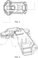
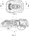
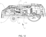
- the autonomous operation device includes: a body 1, a cutting mechanism 2, and a gear mounting mechanism 3.
- the body 1 has an accommodating cavity 4 with an opening facing downwards.
- the cutting mechanism 2 has a cutting body 21, and the cutting body 21 is located at a bottom of the body 1.
- the gear mounting mechanism 3 is connected to the cutting mechanism 2 to configure a height between the cutting body 21 and a traveling surface of the autonomous operation device when the cutting mechanism 2 is mounted to the body 1.
- the height of the cutting mechanism 2 is changed through the gear mounting mechanism 3, so that the height range of the cutting mechanism 2 has been quantified when the autonomous operation device works, and different heights of the autonomous operation device match lawns of different national regulations or height requirements.
- the cutting mechanism 2 has multiple mounting states when mounted to the body 1, and the gear mounting mechanism 3 is used for changing the mounting state of the cutting mechanism 2.
- the different mounting states there are different work height thresholds between the cutting mechanism 2 and the traveling surface of the autonomous operation device when the autonomous operation device is used.
- the work height threshold refers to a minimum or maximum height that the autonomous operation device can use to cut grass with the cutting mechanism in a working process.
- the gear mounting mechanism 3 is disposed to change the height of the cutting mechanism 2 when a cutting structure is mounted, so as to reduce unnecessary distance adjustments for customers, to meet use requirements of customers, and to be more convenient to use. There is no need to develop a plurality of different grinding tools to manufacture a large number of different components according to different cutting heights, so that autonomous operation devices used in different countries or on different lawns may use a large number of identical components, thereby reducing production costs.
- the gear mounting mechanism 3 includes: a first seat 31 and a connecting assembly 32.
- the first seat 31 is connected to the cutting mechanism 2, the connecting assembly 32 extends along a length direction of the body 1, and two ends of the connecting assembly 32 are associated with the first seat 31 and the body 1 separately.
- a distance between at least one end of the connecting assembly 32 and the traveling surface may be configured when the cutting mechanism 2 is mounted, that is, the work height threshold of the cutting mechanism 2 is configured.
- the cutting mechanism 2 has a mounting frame 22 connected to the first seat 31 and the cutting body 21 mounted on the mounting frame 22, and a motor is disposed in the first seat 31 to drive the cutting body 21 to operate.
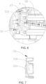
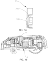
- the gear mounting mechanism 3 further includes a second seat 33, the second seat 33 is disposed opposite the first seat 31 and is connected to the connecting assembly 32, and the second seat 33 is provided with docking portions 331 fitting with some of the limit portions 10.
- FIGs. 6 and 7 show upper and lower limit portions 10 and one docking portion 331.
- the docking portion 331 of the second seat 33 is docked with the upper limit portion 10 to form a mounting state of the cutting mechanism.
- the second seat 33 of another model is used, and the docking portion 331 of the second seat 33 is docked with the lower limit portion 10 to form another mounting state of the cutting mechanism.
- there may be more than two such as three or four limit portions 10 and there may be more than one docking portion 331, which is changed according to a quantity of the limit portions 10; and a quantity of mounting states of the cutting mechanism is also changed with the quantity of the limit portions 10.
- the limit portion 10 is a shoulder, and the docking portion 331 is a hook fitting with the shoulder.
- the limit portion 10 is a groove, and the docking portion 331 is a protruding member; alternatively, the docking portion 331 on the second seat 33 is a shoulder, and the limit portion 10 is a hook, which can achieve the connection between the second seat 33 and the body 1.
- a top of the second seat 33 abuts against a top of the accommodating cavity 4.
- the docking portion 331 fits with the top of the accommodating cavity 4 to limit the second seat 33, so that the second seat 33 is positioned.
- the second seat 33 of different models fit with different limit portions 10.
- the small second seat 33 is selected with the second seat 33 docking with the upper shoulder, and the height of the connection of the connecting assembly 32 to the second seat 33 is raised so that the height of the cutting mechanism 2 is also raised.
- the large second seat 33 is selected with the second seat 33 docking with the lower shoulder, and the height of the connection of the connecting assembly 32 to the second seat 33 is lowered so that the height of the cutting mechanism 2 is also lowered.
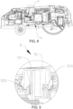
- the large second seat 33 is docked with the lower shoulder in FIGs.
- the model of the second seat 33 may be changed in different autonomous operation devices and then fits with the limit portions 10 at different heights of the body 1 to stably fix the second seat 33 into the same body 1, so that the mounting height of the cutting mechanism 2 is changed. Further, different autonomous operation devices can be produced by replacing only the second seat 33, and costs are reduced.
- the connecting assembly 32 includes a plurality of groups of connecting rods 321 arranged along the height direction of the body 1, and the connecting rods 321 are hinged with the first seat 31 and the second seat 33.
- the first seat 31 is provided with a first mounting slot, and a first connecting shaft 61 passes through the first mounting slot and is connected to the connecting rod 321.
- the second seat 33 is provided with a second mounting slot, and a second connecting shaft 62 passes through the second mounting slot and is connected to the connecting rod 321.
- the height of the second seat 33 may be changed only by the the second seat 33 of a different model .
- the position where the connecting rod 321 is connected to the second seat 33 of the different model remains unchanged. That is, in the second seat 33 of the different model, the distance from the joint between the connecting rod 321 and the second seat 33 to a bottom of the second seat 33 remains unchanged, while the distance from the joint between the connecting rod 321 and the second seat 33 to the top of the second seat 33 changes.
- the second seat 33 of the different model namely, different height, is mounted on the body 1, and the height of the connecting assembly 32 is changed, so that the height of the cutting mechanism 2 is also changed.
- the distance between the at least one end of the connecting assembly 32 and the traveling surface is configured as a work height threshold.
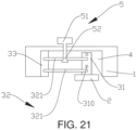
- the gear mounting mechanism 3 further includes a work adjustment mechanism 5 connected to the connecting assembly 32, and the work adjustment mechanism 5 is used for adjusting a work height between the connecting assembly 32 and the traveling surface during the use of the autonomous operation device.
- the work height threshold of each autonomous operation device has been fixed. A user can adjust the work height of the cutting mechanism 2 through the work adjustment mechanism 5 according to use requirements between maximum and minimum work heights to meet the use requirements.
- the autonomous operation device may not have the work adjustment mechanism 5, and the position at which the cutting mechanism 2 is mounted is the only work height of the autonomous operation device.
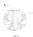
- the connecting assembly 32 has an annular adjustment portion 322, and a bearing surface 320 extending along a circumferential direction and varying in height is configured on a circumferential surface of the annular adjustment portion 322.
- the work adjustment mechanism 5 includes an operation portion 51 and an adjustment rod 52.
- the operation portion 51 is at least partially exposed outside the body 1, and the adjustment rod 52 is connected to the operation portion 51 and inserted into the accommodating cavity 4 to fit with the bearing surface 320.
- the operation portion 51 may be a component such as a knob or a shifter lever.
- the operation portion 51 is rotated to drive the adjustment rod 52 to rotate, and the adjustment rod 52 is rotated to different areas of the bearing surface 320.
- the bearing surface 320 varies in height
- the connecting assembly 32 is lowered to a height as the bottom of the adjustment rod 52 continues abutting against the bearing surface 320 , so that the height of the cutting mechanism 2 is lowered; and when the adjustment rod 52 is rotated towards a lower area of the bearing surface 320, the adjustment rod 52 pulls the connecting assembly 32 to raise, so that the height of the cutting mechanism 2 is raised.
- the connecting rods 321 are arranged in upper and lower rows, and the annular adjustment portions 322 are circular holes formed in the upper row of connecting rods 321, that is, the adjustment rods 52 are connected to the upper row of connecting rods 321.
- adjustment rod 52 is detachably connected to the operation portion 51.
- the length of the adjustment rod 52 is different at different heights between the cutting body 21 and the traveling surface. That is, in the autonomous operation device of the low cutting mechanism 2, when the height of the connecting assembly 32 is lowered, the longer adjustment rod 52 as shown in FIG. 17 may be selected and connected to the connecting assembly 32 and the operation portion 51; and when the connecting assembly 32 is relatively high, the shorter adjustment rod 52 as shown in FIG. 10 may be selected and connected to the connecting assembly 32 and the operation portion 51.
- the height of the cutting mechanism 2 of the autonomous operation device is adjusted through the work adjustment mechanism 5 in work demands, which may be referred to the application public document with the application No. CN202010143005.5 and entitled WORKING MECHANISM AND OPERATION DEVICE. Details are not repeated here.
- a second embodiment of the disclosure relates to an autonomous operation device.
- the second embodiment is roughly the same as the first embodiment, with the main difference being as follows:
- the second seat 33 of different models fit with the limit portions 10 at different heights on the body 1 to form different autonomous operation devices, thereby changing the height of the cutting mechanism 2 during mounting and enabling different autonomous operation devices to have different work height thresholds.
- the models of the second seat 33 remain unchanged, and the mounting positions of the second seat 33 on the body 1 remain unchanged.
- the gear mounting mechanism 3 further includes a second seat 33, which is disposed opposite the first seat 31 and is connected to the connecting assembly 32 and the body 1.
- the second seat 33 has second mounting portions 330, the other end of the connecting assembly 32 fits with some of the second mounting portions 330, and the connecting assembly 32 adjusts the distance between the connecting assembly 32 and the traveling surface during mounting through the second mounting portions 330.
- the second seat 33 has a plurality of second mounting portions 330 arranged along the height direction of the body 1, and the other end of the connecting assembly 32 fits with some of the second mounting portions 330.
- the second mounting portion 330 is a second mounting slot, and the connecting assembly 32 is hinged with the second mounting slot through a second connecting shaft 62.
- the second seat 33 further has a second seat body, and the second mounting portion 330 is detachably connected to the second seat body.
- the second seat body has a plurality of second mounting areas arranged along the height direction of the body 1, and the second mounting portion 330 is mounted to any of the second mounting areas in an operable manner.
- the second mounting areas may be slots with different heights.
- the second mounting portion 330 may be a block structure embedded into the slot. When the height of the second connecting shaft 62 is required to be adjusted, the second mounting portion 330 is embedded into the second mounting area of the corresponding height.
- the second mounting area may alternatively be provided with a hook to hook the second mounting portion 330 and position the second mounting portion 330.
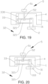
- the connecting assembly 32 has two groups of connecting rods 321 arranged up and down, and the second seat 33 has four rows of the second mounting slots arranged up and down.
- the two groups of connecting rods 321 are connected to the first row and third row of the second mounting slots separately.
- the two groups of connecting rods 321 are connected to the second row and fourth row of the second mounting slots separately. Understandably, in different embodiments, the number of rows of the second mounting slots may be correspondingly changed.
- a third embodiment of the disclosure relates to an autonomous operation device.
- the third embodiment is roughly the same as the second embodiment.
- the first seat 31 has a first mounting portion 310, and the distance between the connecting assembly 32 and the traveling surface during mounting is configured through the first mounting portion 310.
- the first seat 31 has a plurality of first mounting portions 310 arranged along the height direction of the body 1, and one end of the connecting assembly 32 fits with some of the first mounting portions 310.
- first mounting portion 310 is a first mounting slot
- the connecting assembly 32 is hinged with the first mounting slot through a first connecting shaft 61.
- the connecting assembly 32 has two groups of connecting rods 321 arranged up and down, and the first seat 31 has four rows of the first mounting slots arranged up and down.
- the two groups of connecting rods 321 are connected to the first row and third row of the first mounting slots separately.
- the two groups of connecting rods 321 are connected to the second row and fourth row of the first mounting slots separately. Understandably, in different embodiments, the number of rows of the first mounting slots may be correspondingly changed.
- the first seat 31 has a first seat body, and the first mounting portion 310 is detachably connected to the first seat body.
- the first seat body has a plurality of first mounting areas arranged along the height direction of the body, and the first mounting portion is mounted to any of the first mounting areas in an operable manner.
- the first mounting areas may be slots with different heights.
- the first mounting portion 310 may be a block structure embedded into the slot. When the height of the second connecting shaft 62 is required to be adjusted, the first mounting portion 310 is embedded into the first mounting area of the corresponding height.
- the first mounting area may alternatively be provided with a hook to hook the first mounting portion 310 and position the first mounting portion 310.
- the connecting assembly 32 may be directly connected to the body 1, that is, there is no second seat 33.
- this embodiment may be implemented in conjunction with the first embodiment.
- the relevant technical details mentioned in the first embodiment are still valid in this embodiment, and the technical effects that can be achieved in the first embodiment can also be achieved in this embodiment. In order to reduce repetition, details are not repeated here. Correspondingly, the relevant technical details mentioned in this embodiment may also be applied in the first embodiment.
Landscapes
- Life Sciences & Earth Sciences (AREA)
- Environmental Sciences (AREA)
- Harvester Elements (AREA)
Applications Claiming Priority (3)
| Application Number | Priority Date | Filing Date | Title |
|---|---|---|---|
| CN202111134264.2A CN115868309A (zh) | 2021-09-27 | 2021-09-27 | 自主作业设备 |
| CN202122345690.2U CN215683378U (zh) | 2021-09-27 | 2021-09-27 | 自主作业设备 |
| PCT/CN2022/121353 WO2023046171A1 (fr) | 2021-09-27 | 2022-09-26 | Dispositif d'actionnement autonome |
Publications (2)
| Publication Number | Publication Date |
|---|---|
| EP4410084A1 true EP4410084A1 (fr) | 2024-08-07 |
| EP4410084A4 EP4410084A4 (fr) | 2025-10-29 |
Family
ID=85720154
Family Applications (1)
| Application Number | Title | Priority Date | Filing Date |
|---|---|---|---|
| EP22872214.6A Pending EP4410084A4 (fr) | 2021-09-27 | 2022-09-26 | Dispositif d'actionnement autonome |
Country Status (3)
| Country | Link |
|---|---|
| US (1) | US20240397856A1 (fr) |
| EP (1) | EP4410084A4 (fr) |
| WO (1) | WO2023046171A1 (fr) |
Family Cites Families (6)
| Publication number | Priority date | Publication date | Assignee | Title |
|---|---|---|---|---|
| CN105325111B (zh) * | 2014-08-11 | 2018-06-01 | 苏州金莱克精密机械有限公司 | 割草机的无级调高装置 |
| US10524419B1 (en) * | 2017-05-25 | 2020-01-07 | Accelerator Industries, Inc. | Mower deck stabilizer |
| CN111466194B (zh) * | 2019-11-22 | 2026-04-24 | 上海山科机器人有限公司 | 切割机构及割草机 |
| CN113115628B (zh) * | 2020-01-10 | 2025-11-11 | 苏州宝时得电动工具有限公司 | 智能割草机 |
| CN212876737U (zh) * | 2020-06-18 | 2021-04-06 | 苏州宝时得电动工具有限公司 | 自动割草机 |
| CN215683378U (zh) * | 2021-09-27 | 2022-02-01 | 上海山科机器人有限公司 | 自主作业设备 |
-
2022
- 2022-09-26 EP EP22872214.6A patent/EP4410084A4/fr active Pending
- 2022-09-26 WO PCT/CN2022/121353 patent/WO2023046171A1/fr not_active Ceased
- 2022-09-26 US US18/694,987 patent/US20240397856A1/en active Pending
Also Published As
| Publication number | Publication date |
|---|---|
| EP4410084A4 (fr) | 2025-10-29 |
| WO2023046171A1 (fr) | 2023-03-30 |
| US20240397856A1 (en) | 2024-12-05 |
Similar Documents
| Publication | Publication Date | Title |
|---|---|---|
| CN212696649U (zh) | 调高机构、工作机构及作业设备 | |
| EP3195762B1 (fr) | Système de support automatique pour appuie-tête | |
| CN205669244U (zh) | 一种排水沟盖板 | |
| DE112014003752T5 (de) | Drehflügler mit integrierten Lichtleiterstützelementen | |
| CN110463436A (zh) | 割草机 | |
| EP4410084A1 (fr) | Dispositif d'actionnement autonome | |
| CN102615656B (zh) | 剃须机及其套件和使用方法 | |
| EP2491781A1 (fr) | Tondeuse | |
| US20230157206A1 (en) | Trimmer head and trimmer thereof | |
| EP3834598B1 (fr) | Dispositif de réglage de la hauteur de lame de coupe pour tondeuse à gazon robotisée | |
| CN114659198B (zh) | 一种空调器及其控制方法 | |
| KR102518967B1 (ko) | 예초기 헤드 | |
| CN215683378U (zh) | 自主作业设备 | |
| CN111887001B (zh) | 割草机 | |
| US20070181266A1 (en) | Blind fixing core | |
| CN115868309A (zh) | 自主作业设备 | |
| CN212910812U (zh) | 自行走设备 | |
| CN222827692U (zh) | 高度调节机构及割草机 | |
| GB2495577A (en) | Lawnmower having cutting height adjustment | |
| CN115735529A (zh) | 一种割草机 | |
| CN213960792U (zh) | 刀盘辅助调高组件以及割草机 | |
| DE202014005416U1 (de) | Rasenmäher | |
| CN224037955U (zh) | 浮动抬升机构及割草机 | |
| CN215530025U (zh) | 一种单边自动放线打草头 | |
| KR20210098168A (ko) | 높이 조절용 브라켓 |
Legal Events
| Date | Code | Title | Description |
|---|---|---|---|
| STAA | Information on the status of an ep patent application or granted ep patent |
Free format text: STATUS: THE INTERNATIONAL PUBLICATION HAS BEEN MADE |
|
| PUAI | Public reference made under article 153(3) epc to a published international application that has entered the european phase |
Free format text: ORIGINAL CODE: 0009012 |
|
| STAA | Information on the status of an ep patent application or granted ep patent |
Free format text: STATUS: REQUEST FOR EXAMINATION WAS MADE |
|
| 17P | Request for examination filed |
Effective date: 20240426 |
|
| AK | Designated contracting states |
Kind code of ref document: A1 Designated state(s): AL AT BE BG CH CY CZ DE DK EE ES FI FR GB GR HR HU IE IS IT LI LT LU LV MC MK MT NL NO PL PT RO RS SE SI SK SM TR |
|
| A4 | Supplementary search report drawn up and despatched |
Effective date: 20250925 |
|
| RIC1 | Information provided on ipc code assigned before grant |
Ipc: A01D 34/74 20060101AFI20250919BHEP |