EP4410509A1 - Rasoir - Google Patents
Rasoir Download PDFInfo
- Publication number
- EP4410509A1 EP4410509A1 EP23164610.0A EP23164610A EP4410509A1 EP 4410509 A1 EP4410509 A1 EP 4410509A1 EP 23164610 A EP23164610 A EP 23164610A EP 4410509 A1 EP4410509 A1 EP 4410509A1
- Authority
- EP
- European Patent Office
- Prior art keywords
- base
- comb teeth
- blade
- cutting edge
- slot
- Prior art date
- Legal status (The legal status is an assumption and is not a legal conclusion. Google has not performed a legal analysis and makes no representation as to the accuracy of the status listed.)
- Pending
Links
Images



Classifications
-
- B—PERFORMING OPERATIONS; TRANSPORTING
- B26—HAND CUTTING TOOLS; CUTTING; SEVERING
- B26B—HAND-HELD CUTTING TOOLS NOT OTHERWISE PROVIDED FOR
- B26B21/00—Razors of the open or knife type; Safety razors or other shaving implements of the planing type; Hair-trimming devices involving a razor-blade; Equipment therefor
- B26B21/08—Razors of the open or knife type; Safety razors or other shaving implements of the planing type; Hair-trimming devices involving a razor-blade; Equipment therefor involving changeable blades
- B26B21/14—Safety razors with one or more blades arranged transversely to the handle
- B26B21/18—Safety razors with one or more blades arranged transversely to the handle involving blades with two cutting edges
-
- B—PERFORMING OPERATIONS; TRANSPORTING
- B26—HAND CUTTING TOOLS; CUTTING; SEVERING
- B26B—HAND-HELD CUTTING TOOLS NOT OTHERWISE PROVIDED FOR
- B26B21/00—Razors of the open or knife type; Safety razors or other shaving implements of the planing type; Hair-trimming devices involving a razor-blade; Equipment therefor
- B26B21/08—Razors of the open or knife type; Safety razors or other shaving implements of the planing type; Hair-trimming devices involving a razor-blade; Equipment therefor involving changeable blades
- B26B21/14—Safety razors with one or more blades arranged transversely to the handle
- B26B21/18—Safety razors with one or more blades arranged transversely to the handle involving blades with two cutting edges
- B26B21/185—Safety razors with one or more blades arranged transversely to the handle involving blades with two cutting edges with adjustable guard clearance; with variable angle of rake
-
- B—PERFORMING OPERATIONS; TRANSPORTING
- B26—HAND CUTTING TOOLS; CUTTING; SEVERING
- B26B—HAND-HELD CUTTING TOOLS NOT OTHERWISE PROVIDED FOR
- B26B21/00—Razors of the open or knife type; Safety razors or other shaving implements of the planing type; Hair-trimming devices involving a razor-blade; Equipment therefor
- B26B21/40—Details or accessories
- B26B21/4062—Actuating members, e.g. switches or control knobs; Adjustments
-
- B—PERFORMING OPERATIONS; TRANSPORTING
- B26—HAND CUTTING TOOLS; CUTTING; SEVERING
- B26B—HAND-HELD CUTTING TOOLS NOT OTHERWISE PROVIDED FOR
- B26B21/00—Razors of the open or knife type; Safety razors or other shaving implements of the planing type; Hair-trimming devices involving a razor-blade; Equipment therefor
- B26B21/40—Details or accessories
- B26B21/52—Handles, e.g. tiltable, flexible
- B26B21/521—Connection details, e.g. connection to razor heads
Definitions
- the following application relates to the field of personal care products, in particular to a razor.
- Razors are commonly used household goods, which generally include safety shaver, electric razor and manual razor.
- a razor is easy to use with good shaving effect, and convenient to carry, so it is of great significance for daily life.
- An aspect relates to a razor which is able to adapt to various forms of beards, able to groom and guide, and obtain better shaving effect by easy operation.
- the invention is as defined in the dependent claim1. Some embodiments are defined in the dependent claim1.
- the first guide slot and the second guide slot of the shaving head achieve different depths by providing the first comb teeth and the second comb teeth corresponding to the first cutting edge and the second cutting edge with different lengths, in which the first guide slot with a depth adapted to thick, long and messy beards might effectively comb these beards so that the first cutting edge is able to shave them to a shorter state; the second guide slot with a depth adapted to a user's face is able to fit the user's face tightly so that the second cutting edge can shave shorter or initially shaved beards cleanly. Therefore, the first guide slot and the second guide slot might cooperate to comb and guide various forms of hairs for shaving cleanly by the cutting edges, and they have simple structures which are convenient to operate and strongly versatile.
- the first cutting edge extends beyond the root of the first comb teeth by a greater length than the second cutting edge extends beyond the root of the second comb teeth.
- the invention is as defined in the claims 2 to 5.
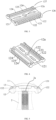
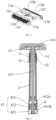
- a razor according to a first embodiment of the present application includes a shaving head 1 and a handle 2, which are attached to each other.
- the shaving head 1 includes a cover body11, a base12 and a blade13.
- the cover body11 includes a cover plate 111 and a connector 112 arranged on one side of the cover plate 111.
- the base 12 is provided with a connecting hole 12a.
- the connector 112 of the cover body 11 passes through the connecting hole 12a such that the cover plate 111 is arranged on the base 12, and the base 12 has at least a first side 12f and a second side 12g that are not covered by the cover body 11.
- the part of the base 12 covered by the cover plate 111 is defined as a holding area that a blade slot 12h is formed between the cover plate 111 and the holding area.
- the blade slot 12h receives the blade 13 which has a first cutting edge 131 facing the first side 12f and a second cutting edge 132 facing the second side 12g.
- the first cutting edge 131 and the second cutting edge 132 are both exposed outside the blade slot 12h but do not extend beyond the first side 12f or second side 12g of the base 12.
- the base 12 includes a carrying plate 121, first comb teeth 122 and second comb teeth 124.
- the first comb teeth 122 and the second comb teeth 124 are vertically arranged on the a first side face 126 and the second side face 127 of the carrying plate 121 and at the same time perpendicular to the first cutting edge 131 and the second cutting edge 132 of the blade 13, respectively.
- the first comb teeth 122, the second comb teeth 124 and the first side face 126 and the second side face 127 of the carrying plate 121 together form the first side 12f and the second side 12g of the base 12.
- Every two adjacent comb teeth of the first comb teeth 122 defines a first guide slot 123 and every two adjacent comb teeth of the second comb teeth 124 defines a second guide slot 125.
- the distance between the two adjacent comb teeth defines the width of the guide slot and the length of the comb teeth defines the depth of the guide slot, in which the depth of the first guide slot 123 is greater than the depth of the second guide slot 125.
- the length of the first cutting edge 131 beyond the root of the first comb teeth 122 is greater than the length of the second cutting edge 132 beyond the root of the second comb teeth 124, i.e., the length of the first cutting edge 131 exposed in the first guide slot 123 is greater than the length of the second cutting edge 132 exposed in the second guide slot 125.
- the first comb teeth 122 with a longer length can form deeper first guide slots 123 so that longer and denser beards can be combed during the shaving process; and because the first cutting edge 131 is exposed in the first guide slots 123 for a longer length, its edge is more exposed so that it can have a faster and more intense shaving effect; thus using the side of shaving head 1 with the first comb teeth 122 and the first cutting edge 131 in conjunction can shave longer and denser beards faster and get neatly combed shorter beards.
- the second comb teeth 124 with a shorter length is more suitable for combing beards of shorter length, and can make the ends of the second guide slots 125 closer to a user's face, so that the distance between the second cutting edge 132 located on the other side of the shaving head land the user's face is shorter in the shaving process, allowing for an effective shaving of short beards; Further, the second cutting edge 132 is exposed in the second guide slots 125 for a shorter length and its edge is less exposed so that a more delicate and soft shaving effect can be obtained. Thus, the user can choose different sides of the shaving head 1 for different results depending on his shaving needs.
- the spacing between the two adjacent first comb teeth 122 is greater than the spacing between the two adjacent second comb teeth 124, i.e. the width of the first guide slots 123 is greater than the width of the second guide slots 125. This allows the first guide slots 123 to easily accommodate more beards and is more suitable for users having longer thicker beards.
- the first guide slot 123 has a slot depth range of 1.5mm to 2.0mm, which may be specifically 1.5mm, 1.6mm, 1.7mm, 1.8mm, 1.9mm, 2.0mm, etc., in one embodiment is 1.7mm. It will be appreciated that the slot depth range allows the first guide slot 123 to accommodate coarse, messy and longer beards, which is able to provide effective combing and guiding of the coarse or messy or longer beards for an initial shaving of the first cutting edge 131.
- the slot depth range of the second guide slot 125 is from 0.3 mm to 0.6 mm, for example, it may be 0.3 mm, 0.4 mm, 0.5 mm, 0.6 mm, etc., in one embodiment is 0.48 mm. It will be appreciated that the slot depth range allows the second guide slot 125 to guide the shorter beards and fit the user's face tightly, facilitating the second cutting edge132 to shave the shorter beards for effectively.
- first comb teeth 122 and the second comb teeth 124 have a convex arc structure with a rounded transitional surface, which can effectively avoid scratching the user's facial skin when combing and guiding bears, improving the comfort and safety during use.
- the guide slots may have different configurations depending on the design of the comb teeth or the carrying plate.
- the first and the second side faces of the carrying plate 121 are both perpendicular to their respective adjacent faces on the carrying plate, and the first comb teeth 122 and the second comb teeth 124 are arranged perpendicular to the first side face 126 and the second side face 127 respectively, such that the first guide slots 123 and the second guide slots 125 formed therein are parallel to the direction from the cover plate to the base.
- FIG. 4 shows a schematic view of the base in some other embodiments, in which the second side face 127 of the carrying plate 121 is a slope surface, and the end close to the cover body 11 is closer to the second cutting edge 132 than the end away from the cover body 11, so that the second guide slot 125 forms an angle with the direction from the cover plate to the base.
- the first comb teeth 122 and the second comb teeth 124 are provided with beard guide sticks 12i on the surfaces of the sides thereof facing the guide slots.
- One end of the beard guide stick is attached to the surface of the comb tooth, the other end with a vector toward the inside of the guide slot and a vector toward the side of the base away from the blade extends towards both the inside of the guide slot and the side of the base away from the blade.
- the beard guide sticks 12i are able to further comb the beards in the guide slots, so as to obtain better results.
- Fig. 5 which shows a further embodiment of the shaving head 1, in which the cover body 11 has a convex arc structure curved toward the base 12, so that its edge is rounded with the outer edge of the first comb teeth 122 or the second comb teeth 124 of the base 12, respectively, to effectively avoid scratching the skin in the process of shaving hair, and improve the comfort of using the razor.
- the angle ⁇ formed between the tangent line between the edge of the cover body 11 near the side of the first cutting edge 131 and the outer edge of the first comb teeth 122 and the extension line of the first cutting edge 131 is 20° to 30°, for example, it may be 20°, 22°, 24°, 26°, 28°, 30°, etc.
- the angular fit between the cover body 11, the first comb teeth 122 and the first cutting edge 131 enables the cutting angle of the blade 13 to fit more closely to the face and improve the comfort of the shaving process while ensuring combing and guiding of thick, long and messy beards.
- the handle 2 is attached to the base 12 of the shaving head 1. Specifically, in this embodiment, one end of the handle 2 is provided with a mounting hole 2a matching the connector 112 of the cover body 11. Passing through the connecting hole 12a of the base 12, the connector 112 of the cover body 11 is inserted into the mounting hole 2a of the handle 2, so that the handle 2 is removably attached to the base 12.
- the shaving head 1 has an integrated cover body 11 and base 12, with a blade slot 12h retained between them to receive the blade 13.
- the handle 2 may either be integrally formed with the base 12 or may be attached to the base 12 in a detachable form.
- This embodiment is a further embodiment of the razor described in the first embodiment.
- the razor further includes a blade adjustment unit 3 and an open-close unit for the cover body 4 for the cover body on the basis of the first embodiment, and accordingly the structures of the shaving head 1 and the handle 2 are improved.
- Fig.7 is a schematic structural view of a base in this embodiment.
- the base 12 with a connecting hole 12a is further provided with a through-hole 12b and a through-hole 12c along the first side 12f and the second side 12g, respectively.
- the first through-hole 12b and the second through-hole 12c are at least partially covered by the first cutting edge 131 or the second cutting edge 132 of the blade 13, respectively.
- One end of the handle 2 is snapped in the connecting hole 12a.
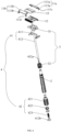
- FIG. 8 shows a partial cross-sectional view of the blade adjustment unit 3 and the open-close unit for the cover body 4 installed with the base 12 and the handle 2.
- the blade adjustment unit 3 includes an adjustment frame 31 and an auxiliary adjusting mechanism 32.
- the adjustment frame 31 includes a bed 311, a first contact block 312 and a second contact block 313.
- the bed 311 is movably sleeved on an end of the handle 2 near the base 12 and the bed 311 has a first surface 315 facing the base 12.
- the first contact block 312 and the second contact block 313 are arranged on the first surface 315 of the bed 311, passing through the first through-hole 12b or the second through-hole 12c of the base 12 and against the inside of the first cutting edge 131 or the second cutting edge 132 of the blade 13, respectively.
- the auxiliary adjusting mechanism 32 is used to provide auxiliary adjustment of the position of the adjustment frame 31 on the handle 2.
- the auxiliary adjusting mechanism 32 is an adjusting knob 421 sleeved on the handle 2 and against the side of the adjustment frame 31 away from the base 12.
- a matching first drive thread pair 5 is provided between the knob 421 and the handle 2, turning the adjusting knob 421 along the matching first drive thread pair 5 allows the adjusting knob 421 to be moved up and down along the handle 2.
- the heights of the first contact block 312 and the second contact block 313 through the base 12 are able to adjust so that the distances of the abutted first cutting edge 131 and the second cutting edge 132 to the base 12 are able to adjust and thus the intensity of cutting edges are changed.
- the adjustment frame 31 is pushed towards the base 12 and the heights of the first contact block 312 and the second contact block 313 through the base 12 increase, causing the first cutting edge 131 and the second cutting edge 132 to be pushed up away from the base 12; and as the distances between the contact blocks and the cover body 11 become smaller, the blade 13 subjected to both forces at the same time decreases its deformation degree which makes its intensity increase, therefore suitable for people with thicker and harder beards.
- the adjustment frame 31 will follow the auxiliary adjusting mechanism 32 under the elastic force of the blade 13, so that the heights of the first contact block 312 and the second contact block 313 through the base 12 decrease, and the distances between the first cutting edge 131 and the second cutting edge132 to the base 12 also decrease accordingly; and as the distances between the contact blocks and the cover body 11 become larger, the deformation degree of the blade 13 also increases, resulting in a less intense and softer blade, suitable for people with finer and softer beards and more sensitive skin.
- the auxiliary adjusting mechanism 32 is provided to enable the user to adjust the position of the adjustment frame 31 more conveniently and to indirectly achieve adjustment of the distances between the cutting edges and the base 12, as well as its degree of intensity. Therefore, except for the adjusting knob 421 used in this embodiment, in some other embodiments, the auxiliary adjusting mechanism 32 might also achieve the same auxiliary adjustment in other ways. While in some other embodiments, the blade adjustment unit 3 may also include only a contact block, and a user may directly adjust the position of the contact block on the handle 2, thus realizing the adjustment of the cutting edges.
- the adjustment frame 31 includes a plurality of first contact blocks 312 and the second contact blocks 313, which are spaced on the first surface 315 of the bed 311, respectively. Accordingly, the base 12 is also spaced with a corresponding quantity of first through-holes 12b and the second through-holes 12c. The plurality of the first contact blocks 312 and the second contact blocks 313 provide a more even adjustment effect for the blade 13, while the spaced through-holes provide a stronger strength for the base 12.
- the adjusting frame 31 further includes at least one limit block 314, which is arranged on the first surface 315 of the bed 311 with a height less than the heights of the first contact block 312 and the second contact block 313, and the difference between the heights of the first contact block 312 or second contact block 313 and the limit block 314 is less than the height of the blade slot 12h.
- the limit block 314 abuts against the base 12 when the adjustment frame 31 with the limit block 314 moves towards the base 12, so as to prevent the first contact block 312 or second contact block 313 passing through the through-holes for a length too much to damage to the blade 13.
- the limit block 314 is arranged between the first contact block 312 and the second contact block 313 and attached to both. It can provide further support for the first contact block 312 and the second contact block 313, in addition to play a limiting role.
- a plurality of limit blocks 314 might also be provided accordingly, so that each first block 312 and second block 313 can obtain sufficient support, and the adjustment frame 31 has a better overall strength.
- the handle 2 in order to prevent the blade adjustment unit 3 from moving too far away the base 12 and disengaging the first contact block 312 and the second contact block 313 from the base 12, the handle 2 is further provided with a first limit part 21 for limiting the blade adjustment unit 3.
- the first limit part 21 is a bump arranged on the outside of the handle 2, with a distance from the base 12 less than the overall length of the blade adjustment unit 3.
- the first limit part 21 defines the maximum distance that the blade adjustment unit 3 can move away from the base 12, thus avoiding the situation where the first contact block 312 and the second contact block 313 are detached from the base 12 due to excessive movement.
- the open-close unit for the cover body 4 includes a drive member 41 and a control assembly 42.
- Fig. 10 shows a schematic structural view of the open-close unit for the cover body 4 in which the cover body 11 is open.
- the drive member 41 includes a connecting rod 412 and a hinge joint 411, one end of the connecting rod 412 attached to the hinge joint 411 and the other end of the connecting rod 412 passing through the connecting hole 12a in the base 12 and penetrating the handle 2.
- the hinge joint 411 is unable to pass through the connecting hole 12a, as when the connecting rod 412 moves from the base 12 toward the handle 2, the hinge joint 411 is stuck on the side of the base 12 away from the handle 2.
- the cover body 11 is arranged in a form with divided parts, which includes a first sub-cover 11a and a second sub-cover 11b arranged side by side, the first sub-cover 11a including a first sub-cover plate 111a and a first connecting arm 113a, the second sub-cover 11b including a second sub-cover plate 111b and a second connecting arm 113b, the first connecting arm 113a and the second connecting arm 113b respectively arranged on the sides of the first sub-cover plate 111a and the second sub-cover plate 111b near the base 12.
- the first connecting arm 113a and the second connecting arm 113b are respectively rotatably attached to the hinge joint 411, both of which rotate around the hinge joint 411 in opposite directions to bring the first and the second sub-cover plates 111a and 111b together, or separate the sub-cover plate 111a and the second sub-cover plate 111b from each other.
- the base 12 is provided with a first limit element12d and a second limit
- the first limit element 12d and the second limit element 12e of the base 12 are hooks arranged respectively on opposite sides of the carrying plate 121 and protruding towards each other.
- the end of the first connecting arm 113a of the first sub-cover 11a away from the first sub-cover plate 111a is bent to form a first limit hook 113c; and the end of the second connecting arm 113b of the second sub-cover 11b away from the second sub-cover plate 111b is bent to form a second limit hook 113d.
- the first limit hook 113c and the second limit hook 113d extend in opposite directions after respectively attached to the hinge joint 411.
- the first limit hook 113c and the second limit hook 113d are oriented in opposite directions and are hooked by the first limit element 12d and the second limit element 12e respectively, after the first sub-cover 11a and the second sub-cover 11b are assembled to the base 12.
- the hinge joint 411 of the drive member 41 is attached to the bending parts of the first limit hook 113c and the second limit hook 113d, respectively.
- the connection part of the first connecting arm 113a and the second connecting arm 113b with the hinge joint 411 will follow the movement of the drive member 41 and move away from the base 12, and at the same time, the first connecting arm 113a and the second connecting arm 113b are unable to leave the base 12 as a whole due to the hooking of the first limit element 12d or second limit element 12e, but able to only rotate around the first limit element 12d or second limit element 12e and drive the first sub-cover 11a and the second sub-cover 11b to rotate around the hinge joint 411 in opposite directions and move away from each other to separate the first sub-cover plate 111a and the second sub-cover plate 111b to open the cover body.
- connection points of the first connecting arm 113a and the second connecting arm 113b with the hinge joint 411 will follow the drive member 41 to move closer to the base 12, while the two connecting arms are only able to rotate around the first limit element 12d or the second limit element 12e due to the hooking of the first limit element 12d or second limit element 12e and drive the first sub-cover 11a and the second sub-cover 11b to rotate around the hinge joint 411 in opposite directions different from previous directions and move towards each other to bring the first sub-cover plate 111a and the second sub-cover plate 111b together to close the cover body.
- the limit elements serve to limit the way in which the connecting arms are unable to move to detach from the base 12 as a whole and thus limit its movement.
- the connecting arm may be hinged to both the limit elements of the base 12 and the connecting part of the drive member 41, which may also achieve the above effect.
- the cover body 11 may be a single unit without being divided into a first sub-cover 11a and a second sub-cover 11b, which includes a cover plate and an connecting arm, in which the connecting arm is arranged on the side of the cover plate near the base and is pivotally attached to an articulated portion of the drive member.
- the base is provided with a limit element for restraining the connecting arm.
- the control assembly 42 includes a knob 421 and an internal rotating block 422, in which the knob 421 is attached to the end of the handle 2 away from the base 12 and is rotatable about the handle 2.
- the internal rotating block 422 is snapped on the connecting rod 412 of the drive member 41 and is arranged inside the knob 421.
- the inner side of the knob 421 and the outer side of the internal rotation block 422 are provided with a matching second drive thread pair 6. With the cooperation of the second drive thread pair 6, the internal rotating block 422 is able to move up and down within the knob 421 by simply turning the knob 421, thus driving the connecting rod 412 to move relative to the handle 2 and realize the opening and closing of the cover body 11.
- the knob 421 is attached to the end of the handle 2 by means of a snap spring. In other embodiments, the knob 421 may also be otherwise attached to the handle 2 as long as it is rotatable around the handle 2 and will not detach from the handle 2. In some embodiments, the internal rotating block 422 is also snap-fitted within the knob 421 by means of a snap spring, which effectively prevents the internal rotating block 422 from detaching from the knob 421.
- control assembly 42 further includes a top tightening member 423
- the connecting rod 412 is provided with a first stuck element 412a and a second stuck element 412b, in which the internal rotating block 422 is arranged between the first stuck element 412a and the second stuck element 412b, and the top tightening member 423 is arranged between the internal rotating block 422 and the second stuck element 412b and fastens the internal rotating block 422 to the first stuck element 412a, thereby enabling the internal rotating block 422 to be stuck on the connecting rod 412.
- the top tightening member 423 might be an elastic part in compression state, which able to exert continuous pressure on the internal rotating block 422 and tighten it to the first stuck element 412a, so that the internal rotating block 422 needs to overcome more resistance to be rotated, which able to avoid a user to open the cover body 11 by mistake.
- the second stuck element 412b may be detachably arranged on the connecting rod 412 so that a user can conveniently disassemble, replace parts and reassemble the razor as a whole.
Landscapes
- Life Sciences & Earth Sciences (AREA)
- Forests & Forestry (AREA)
- Engineering & Computer Science (AREA)
- Mechanical Engineering (AREA)
- Dry Shavers And Clippers (AREA)
- Knives (AREA)
Applications Claiming Priority (1)
| Application Number | Priority Date | Filing Date | Title |
|---|---|---|---|
| CN202320151764.5U CN218965478U (zh) | 2023-02-03 | 2023-02-03 | 一种剃须刀 |
Publications (1)
| Publication Number | Publication Date |
|---|---|
| EP4410509A1 true EP4410509A1 (fr) | 2024-08-07 |
Family
ID=86007372
Family Applications (1)
| Application Number | Title | Priority Date | Filing Date |
|---|---|---|---|
| EP23164610.0A Pending EP4410509A1 (fr) | 2023-02-03 | 2023-03-28 | Rasoir |
Country Status (3)
| Country | Link |
|---|---|
| US (1) | US12447640B2 (fr) |
| EP (1) | EP4410509A1 (fr) |
| CN (1) | CN218965478U (fr) |
Citations (5)
| Publication number | Priority date | Publication date | Assignee | Title |
|---|---|---|---|---|
| FR423887A (fr) * | 1910-07-30 | 1911-04-28 | Luigi Brunacci | Rasoir de sureté |
| US1343900A (en) * | 1919-06-30 | 1920-06-22 | Brasier William Harry | Razor |
| US1934148A (en) * | 1930-10-16 | 1933-11-07 | William C Rogers | Safety razor |
| US1942911A (en) * | 1930-12-01 | 1934-01-09 | Ashworth Advertising Company I | Safety razor |
| US1999941A (en) * | 1932-08-13 | 1935-04-30 | Joseph E Mcwilliams | Safety razor |
Family Cites Families (10)
| Publication number | Priority date | Publication date | Assignee | Title |
|---|---|---|---|---|
| US2359198A (en) * | 1944-03-17 | 1944-09-26 | Orville C Bowers | Safety razor |
| US2710446A (en) * | 1952-06-02 | 1955-06-14 | Kamekichi Shibayama | Guard for safety razors |
| US2715768A (en) * | 1952-10-30 | 1955-08-23 | Hoberg Paul | Rotatable blade clamping safety razor |
| US2720695A (en) * | 1953-10-12 | 1955-10-18 | Sabiers Charles | Combined safety razor and hair trimmer |
| US2795847A (en) * | 1955-02-24 | 1957-06-18 | Arnade Kurt Conrad | Instrument for surgical shaving |
| WO2012028171A1 (fr) | 2010-08-30 | 2012-03-08 | Bic-Violex Sa | Capuchon de protection pour cartouche de rasoir |
| US10807256B2 (en) * | 2014-09-12 | 2020-10-20 | Rockwell Razors Corporation | Modular safety razor with adjustable blade angle |
| US9505142B2 (en) * | 2014-09-12 | 2016-11-29 | Rockwell Razors Corporation | Modular safety razor with adjustable blade angle |
| CN204183583U (zh) | 2014-10-31 | 2015-03-04 | 黄志坚 | 双面剃须刀 |
| CN216543425U (zh) | 2021-12-21 | 2022-05-17 | 广州威的科技有限公司 | 一种剃须刀片的安装结构及其剃须刀 |
-
2023
- 2023-02-03 CN CN202320151764.5U patent/CN218965478U/zh active Active
- 2023-03-28 EP EP23164610.0A patent/EP4410509A1/fr active Pending
- 2023-03-29 US US18/127,972 patent/US12447640B2/en active Active
Patent Citations (5)
| Publication number | Priority date | Publication date | Assignee | Title |
|---|---|---|---|---|
| FR423887A (fr) * | 1910-07-30 | 1911-04-28 | Luigi Brunacci | Rasoir de sureté |
| US1343900A (en) * | 1919-06-30 | 1920-06-22 | Brasier William Harry | Razor |
| US1934148A (en) * | 1930-10-16 | 1933-11-07 | William C Rogers | Safety razor |
| US1942911A (en) * | 1930-12-01 | 1934-01-09 | Ashworth Advertising Company I | Safety razor |
| US1999941A (en) * | 1932-08-13 | 1935-04-30 | Joseph E Mcwilliams | Safety razor |
Also Published As
| Publication number | Publication date |
|---|---|
| CN218965478U (zh) | 2023-05-05 |
| US12447640B2 (en) | 2025-10-21 |
| US20240261991A1 (en) | 2024-08-08 |
Similar Documents
| Publication | Publication Date | Title |
|---|---|---|
| RU2703947C1 (ru) | Гребенчатое приспособление, режущая головка и прибор для стрижки волос | |
| JP7564242B2 (ja) | 電気髭トリマー | |
| CN206011158U (zh) | 可释放附件梳及切割头 | |
| RU2651550C1 (ru) | Режущая головка и устройство для срезания волос | |
| EP2227359B1 (fr) | Dispositif de rasage comprenant un ensemble d'éléments de coupe agencé de manière pivotante | |
| US5054199A (en) | Hair cutter | |
| RU2700884C2 (ru) | Режущая головка и устройство для стрижки волос | |
| EP2095914A2 (fr) | Rasoir électrique | |
| KR100803865B1 (ko) | 이발기 | |
| CN115023324B (zh) | 电动胡须修剪器 | |
| JP2019171034A (ja) | 体毛除去装置 | |
| WO2021213531A1 (fr) | Cartouche de lame de rasoir à mouvement alternatif et son procédé de fabrication | |
| JPH08502911A (ja) | ひげそり補助剤を有する回転型ひげそり装置 | |
| WO2008068952A1 (fr) | Dispositif de coupe de cheveux | |
| KR200409341Y1 (ko) | 헤드무빙 전기면도기 | |
| EP4410509A1 (fr) | Rasoir | |
| JP5879531B2 (ja) | 電気かみそり | |
| JP2000005460A (ja) | 往復式電気かみそり | |
| WO2022250566A1 (fr) | Nécessaire de rasage | |
| JP2002273072A (ja) | 電気かみそり | |
| US20240316809A1 (en) | Razor with intermittent encapsulation of embedded blades | |
| KR200428926Y1 (ko) | 90° 헤드틸팅 면도기 | |
| KR200426464Y1 (ko) | 슬림형 전기면도기의 헤드틸팅장치 | |
| KR200381160Y1 (ko) | 휴대용 눈썹면도기 | |
| JP2519248Y2 (ja) | 電気かみそり |
Legal Events
| Date | Code | Title | Description |
|---|---|---|---|
| PUAI | Public reference made under article 153(3) epc to a published international application that has entered the european phase |
Free format text: ORIGINAL CODE: 0009012 |
|
| STAA | Information on the status of an ep patent application or granted ep patent |
Free format text: STATUS: REQUEST FOR EXAMINATION WAS MADE |
|
| 17P | Request for examination filed |
Effective date: 20231109 |
|
| AK | Designated contracting states |
Kind code of ref document: A1 Designated state(s): AL AT BE BG CH CY CZ DE DK EE ES FI FR GB GR HR HU IE IS IT LI LT LU LV MC ME MK MT NL NO PL PT RO RS SE SI SK SM TR |
|
| GRAP | Despatch of communication of intention to grant a patent |
Free format text: ORIGINAL CODE: EPIDOSNIGR1 |
|
| STAA | Information on the status of an ep patent application or granted ep patent |
Free format text: STATUS: GRANT OF PATENT IS INTENDED |
|
| INTG | Intention to grant announced |
Effective date: 20260302 |