EP4410532A1 - Panneaux composites et leurs procédés de fabrication - Google Patents
Panneaux composites et leurs procédés de fabrication Download PDFInfo
- Publication number
- EP4410532A1 EP4410532A1 EP24154428.7A EP24154428A EP4410532A1 EP 4410532 A1 EP4410532 A1 EP 4410532A1 EP 24154428 A EP24154428 A EP 24154428A EP 4410532 A1 EP4410532 A1 EP 4410532A1
- Authority
- EP
- European Patent Office
- Prior art keywords
- face
- composite
- cells
- composite panel
- cross
- Prior art date
- Legal status (The legal status is an assumption and is not a legal conclusion. Google has not performed a legal analysis and makes no representation as to the accuracy of the status listed.)
- Pending
Links
Images


Classifications
-
- B—PERFORMING OPERATIONS; TRANSPORTING
- B32—LAYERED PRODUCTS
- B32B—LAYERED PRODUCTS, i.e. PRODUCTS BUILT-UP OF STRATA OF FLAT OR NON-FLAT, e.g. CELLULAR OR HONEYCOMB, FORM
- B32B9/00—Layered products comprising a layer of a particular substance not covered by groups B32B11/00 - B32B29/00
- B32B9/04—Layered products comprising a layer of a particular substance not covered by groups B32B11/00 - B32B29/00 comprising such particular substance as the main or only constituent of a layer, which is next to another layer of the same or of a different material
-
- B—PERFORMING OPERATIONS; TRANSPORTING
- B32—LAYERED PRODUCTS
- B32B—LAYERED PRODUCTS, i.e. PRODUCTS BUILT-UP OF STRATA OF FLAT OR NON-FLAT, e.g. CELLULAR OR HONEYCOMB, FORM
- B32B3/00—Layered products comprising a layer with external or internal discontinuities or unevennesses, or a layer of non-planar shape; Layered products comprising a layer having particular features of form
- B32B3/10—Layered products comprising a layer with external or internal discontinuities or unevennesses, or a layer of non-planar shape; Layered products comprising a layer having particular features of form characterised by a discontinuous layer, i.e. formed of separate pieces of material
- B32B3/12—Layered products comprising a layer with external or internal discontinuities or unevennesses, or a layer of non-planar shape; Layered products comprising a layer having particular features of form characterised by a discontinuous layer, i.e. formed of separate pieces of material characterised by a layer of regularly- arranged cells, e.g. a honeycomb structure
-
- B—PERFORMING OPERATIONS; TRANSPORTING
- B32—LAYERED PRODUCTS
- B32B—LAYERED PRODUCTS, i.e. PRODUCTS BUILT-UP OF STRATA OF FLAT OR NON-FLAT, e.g. CELLULAR OR HONEYCOMB, FORM
- B32B33/00—Layered products characterised by particular properties or particular surface features, e.g. particular surface coatings; Layered products designed for particular purposes not covered by another single class
-
- B—PERFORMING OPERATIONS; TRANSPORTING
- B32—LAYERED PRODUCTS
- B32B—LAYERED PRODUCTS, i.e. PRODUCTS BUILT-UP OF STRATA OF FLAT OR NON-FLAT, e.g. CELLULAR OR HONEYCOMB, FORM
- B32B37/00—Methods or apparatus for laminating, e.g. by curing or by ultrasonic bonding
- B32B37/12—Methods or apparatus for laminating, e.g. by curing or by ultrasonic bonding characterised by using adhesives
-
- B—PERFORMING OPERATIONS; TRANSPORTING
- B32—LAYERED PRODUCTS
- B32B—LAYERED PRODUCTS, i.e. PRODUCTS BUILT-UP OF STRATA OF FLAT OR NON-FLAT, e.g. CELLULAR OR HONEYCOMB, FORM
- B32B5/00—Layered products characterised by the non- homogeneity or physical structure, i.e. comprising a fibrous, filamentary, particulate or foam layer; Layered products characterised by having a layer differing constitutionally or physically in different parts
- B32B5/14—Layered products characterised by the non- homogeneity or physical structure, i.e. comprising a fibrous, filamentary, particulate or foam layer; Layered products characterised by having a layer differing constitutionally or physically in different parts characterised by a layer differing constitutionally or physically in different parts, e.g. denser near its faces
-
- B—PERFORMING OPERATIONS; TRANSPORTING
- B32—LAYERED PRODUCTS
- B32B—LAYERED PRODUCTS, i.e. PRODUCTS BUILT-UP OF STRATA OF FLAT OR NON-FLAT, e.g. CELLULAR OR HONEYCOMB, FORM
- B32B9/00—Layered products comprising a layer of a particular substance not covered by groups B32B11/00 - B32B29/00
- B32B9/005—Layered products comprising a layer of a particular substance not covered by groups B32B11/00 - B32B29/00 comprising one layer of ceramic material, e.g. porcelain, ceramic tile
- B32B9/007—Layered products comprising a layer of a particular substance not covered by groups B32B11/00 - B32B29/00 comprising one layer of ceramic material, e.g. porcelain, ceramic tile comprising carbon, e.g. graphite, composite carbon
-
- B—PERFORMING OPERATIONS; TRANSPORTING
- B33—ADDITIVE MANUFACTURING TECHNOLOGY
- B33Y—ADDITIVE MANUFACTURING, i.e. MANUFACTURING OF THREE-DIMENSIONAL [3D] OBJECTS BY ADDITIVE DEPOSITION, ADDITIVE AGGLOMERATION OR ADDITIVE LAYERING, e.g. BY 3D PRINTING, STEREOLITHOGRAPHY OR SELECTIVE LASER SINTERING
- B33Y80/00—Products made by additive manufacturing
-
- B—PERFORMING OPERATIONS; TRANSPORTING
- B32—LAYERED PRODUCTS
- B32B—LAYERED PRODUCTS, i.e. PRODUCTS BUILT-UP OF STRATA OF FLAT OR NON-FLAT, e.g. CELLULAR OR HONEYCOMB, FORM
- B32B2250/00—Layers arrangement
- B32B2250/03—3 layers
-
- B—PERFORMING OPERATIONS; TRANSPORTING
- B32—LAYERED PRODUCTS
- B32B—LAYERED PRODUCTS, i.e. PRODUCTS BUILT-UP OF STRATA OF FLAT OR NON-FLAT, e.g. CELLULAR OR HONEYCOMB, FORM
- B32B2250/00—Layers arrangement
- B32B2250/40—Symmetrical or sandwich layers, e.g. ABA, ABCBA, ABCCBA
-
- B—PERFORMING OPERATIONS; TRANSPORTING
- B32—LAYERED PRODUCTS
- B32B—LAYERED PRODUCTS, i.e. PRODUCTS BUILT-UP OF STRATA OF FLAT OR NON-FLAT, e.g. CELLULAR OR HONEYCOMB, FORM
- B32B2260/00—Layered product comprising an impregnated, embedded, or bonded layer wherein the layer comprises an impregnation, embedding, or binder material
- B32B2260/02—Composition of the impregnated, bonded or embedded layer
- B32B2260/021—Fibrous or filamentary layer
-
- B—PERFORMING OPERATIONS; TRANSPORTING
- B32—LAYERED PRODUCTS
- B32B—LAYERED PRODUCTS, i.e. PRODUCTS BUILT-UP OF STRATA OF FLAT OR NON-FLAT, e.g. CELLULAR OR HONEYCOMB, FORM
- B32B2305/00—Condition, form or state of the layers or laminate
- B32B2305/02—Cellular or porous
- B32B2305/024—Honeycomb
-
- B—PERFORMING OPERATIONS; TRANSPORTING
- B32—LAYERED PRODUCTS
- B32B—LAYERED PRODUCTS, i.e. PRODUCTS BUILT-UP OF STRATA OF FLAT OR NON-FLAT, e.g. CELLULAR OR HONEYCOMB, FORM
- B32B2307/00—Properties of the layers or laminate
- B32B2307/10—Properties of the layers or laminate having particular acoustical properties
- B32B2307/102—Insulating
-
- B—PERFORMING OPERATIONS; TRANSPORTING
- B32—LAYERED PRODUCTS
- B32B—LAYERED PRODUCTS, i.e. PRODUCTS BUILT-UP OF STRATA OF FLAT OR NON-FLAT, e.g. CELLULAR OR HONEYCOMB, FORM
- B32B2307/00—Properties of the layers or laminate
- B32B2307/30—Properties of the layers or laminate having particular thermal properties
- B32B2307/306—Resistant to heat
- B32B2307/3065—Flame resistant or retardant, fire resistant or retardant
-
- B—PERFORMING OPERATIONS; TRANSPORTING
- B32—LAYERED PRODUCTS
- B32B—LAYERED PRODUCTS, i.e. PRODUCTS BUILT-UP OF STRATA OF FLAT OR NON-FLAT, e.g. CELLULAR OR HONEYCOMB, FORM
- B32B2315/00—Other materials containing non-metallic inorganic compounds not provided for in groups B32B2311/00 - B32B2313/04
- B32B2315/02—Ceramics
-
- B—PERFORMING OPERATIONS; TRANSPORTING
- B32—LAYERED PRODUCTS
- B32B—LAYERED PRODUCTS, i.e. PRODUCTS BUILT-UP OF STRATA OF FLAT OR NON-FLAT, e.g. CELLULAR OR HONEYCOMB, FORM
- B32B2607/00—Walls, panels
Definitions
- the present disclosure relates to composite panels, and more particularly, composite panels with core structures having a plurality of hollow cells.
- CMCs Reinforced ceramic matrix composites
- Such composites typically have high strength-to-weight ratio and maintain this attribute over a broad range of temperatures that exceeds metallic alloys. This renders them attractive in applications in which weight is a concern and high temperature structural attributes highly constrain the design of components and systems, such as in aeronautic and space vehicle applications.
- Their stability at high temperatures renders CMCs very suitable in applications in which components are in contact with a high-temperature gas, such as in a gas turbine engine and re-entry conditions of space vehicles in terrestrial and non-terrestrial environments.
- Noise suppression technology has a wide variety of industrial and residential applications. Noise suppression devices are often applied in heating ventilation and air conditioning (HVAC) systems, industrial machinery and complexes, transportation vehicles, and any machinery that may tend to produce unacceptably high levels of noise.
- HVAC heating ventilation and air conditioning
- first, second, and third may be used interchangeably to distinguish one component from another and are not intended to signify location or importance of the individual components.
- At least one of' in the context of, e.g., "at least one of A, B, and C” refers only A, only B, only C, or any combination of A, B, and C.
- turbomachine or “turbomachinery” refers to a machine including one or more compressors, a heat generating section (e.g., a combustion section), and one or more turbines that together generate a torque output.
- a heat generating section e.g., a combustion section
- turbines that together generate a torque output.
- gas turbine engine refers to an engine having a turbomachine as all or a portion of its power source.
- Example gas turbine engines include turbofan engines, turboprop engines, turbojet engines, turboshaft engines, etc., as well as hybrid-electric versions of one or more of these engines.
- ceramic matrix composite refers to a class of materials that include a reinforcing material (e.g., reinforcing fibers) surrounded by a ceramic matrix phase. Generally, the reinforcing fibers provide structural integrity to the ceramic matrix.
- matrix materials of CMCs can include, but are not limited to, non-oxide silicon-based materials (e.g., silicon carbide, silicon nitride, or mixtures thereof), oxide ceramics (e.g., silicon oxycarbides, silicon oxynitrides, aluminum oxide (Al 2 O 3 ), silicon dioxide (SiOz), aluminosilicates, or mixtures thereof), or mixtures thereof.
- ceramic particles e.g., oxides of Si, Al, Zr, Y, and combinations thereof
- inorganic fillers e.g., pyrophyllite, wollastonite, mica, talc, kyanite, and montmorillonite
- CMC matrix may also be included within the CMC matrix.
- reinforcing fibers of CMCs can include, but are not limited to, non-oxide silicon-based materials (e.g., silicon carbide, silicon nitride, or mixtures thereof), non-oxide carbon-based materials (e.g., carbon), oxide ceramics (e.g., silicon oxycarbides, silicon oxynitrides, aluminum oxide (Al 2 O 3 ), silicon dioxide (SiOz), aluminosilicates such as mullite, or mixtures thereof), or mixtures thereof.
- non-oxide silicon-based materials e.g., silicon carbide, silicon nitride, or mixtures thereof
- non-oxide carbon-based materials e.g., carbon
- oxide ceramics e.g., silicon oxycarbides, silicon oxynitrides, aluminum oxide (Al 2 O 3 ), silicon dioxide (SiOz), aluminosilicates such as mullite, or mixtures thereof.
- CMCs may be referred to as their combination of type of fiber/type of matrix.
- C/SiC for carbon-fiber-reinforced silicon carbide
- SiC/SiC for silicon carbide-fiber-reinforced silicon carbide
- SiC/SiN for silicon carbide fiber-reinforced silicon nitride
- SiC/SiC-SiN for silicon carbide fiber-reinforced silicon carbide/silicon nitride matrix mixture
- the CMCs may include a matrix and reinforcing fibers comprising oxide-based materials such as aluminum oxide (Al 2 O 3 ), silicon dioxide (SiO 2 ), aluminosilicates, and mixtures thereof.
- Aluminosilicates can include crystalline materials such as mullite (3Al 2 O 3 2SiO 2 ), as well as glassy aluminosilicates.
- the reinforcing fibers may be bundled or coated prior to inclusion within the matrix.
- bundles of the fibers may be formed as a reinforced tape, such as a unidirectional reinforced tape.
- a plurality of the tapes may be laid up together to form a preform component.
- the bundles of fibers may be impregnated with a slurry composition prior to forming the preform or after formation of the preform.
- the preform may then undergo thermal processing, such as a cure or burn-out to yield a high char residue in the preform, and subsequent chemical processing, such as melt-infiltration with silicon, to arrive at a component formed of a CMC material having a desired chemical composition.
- Such materials are particularly suitable for higher temperature applications. Additionally, these ceramic materials are lightweight compared to superalloys, yet can still provide strength and durability to the component made therefrom. Therefore, such materials are currently being considered for many gas turbine, space vehicle structure, and propulsion components used in higher temperature sections, such as airfoils (e.g., turbines, and vanes), combustors, shrouds and other like components, nozzles, transition ducts, thermal protection systems, TPS, aerodynamic control surfaces and leading edges that would benefit from the lighter-weight and higher temperature capability these materials can offer.
- airfoils e.g., turbines, and vanes
- combustors e.g., turbines, and vanes
- shrouds and other like components e.g., nozzles, transition ducts, thermal protection systems, TPS, aerodynamic control surfaces and leading edges that would benefit from the lighter-weight and higher temperature capability these materials can offer.
- additive manufacturing refers generally to manufacturing technology in which components are manufactured in a layer-by-layer manner.
- An exemplary additive manufacturing machine may be configured to utilize any suitable additive manufacturing technology.
- the additive manufacturing machine may utilize an additive manufacturing technology that includes a powder bed fusion (PBF) technology, such as a direct metal laser melting (DMLM) technology, a selective laser melting (SLM) technology, a directed metal laser sintering (DMLS) technology, or a selective laser sintering (SLS) technology.
- PBF powder bed fusion
- DMLM direct metal laser melting
- SLM selective laser melting
- DMLS directed metal laser sintering
- SLS selective laser sintering
- Additively manufactured objects are generally monolithic in nature and may have a variety of integral sub-components.
- suitable additive manufacturing technologies may include, for example, Binder Jet technology, Fused Deposition Modeling (FDM) technology, Direct Energy Deposition (DED) technology, Laser Engineered Net Shaping (LENS) technology, Laser Net Shape Manufacturing (LNSM) technology, Direct Metal Deposition (DMD) technology, Digital Light Processing (DLP) technology, and other additive manufacturing technologies that utilize an energy beam or other energy source to solidify an additive manufacturing material such as a powder material.
- FDM Fused Deposition Modeling
- DED Direct Energy Deposition
- LENS Laser Engineered Net Shaping
- LNSM Laser Net Shape Manufacturing
- DMD Direct Metal Deposition
- DLP Digital Light Processing
- Additive manufacturing technology may generally be described as fabrication of objects by building objects point-by-point, line-by-line, layer-by-layer, typically in a vertical direction. Other methods of fabrication are contemplated and within the scope of the present disclosure. For example, although the discussion herein refers to the addition of material to form successive layers, the presently disclosed subject matter may be practiced with any additive manufacturing technology or other manufacturing technology, including layer-additive processes, layer-subtractive processes, or hybrid processes.
- the material may be metal, ceramic, polymer, epoxy, photopolymer resin, plastic, or any other suitable material that may be in solid, powder, sheet material, wire, or any other suitable form, or combinations thereof.
- exemplary materials may include metals, ceramics, or binders, as well as combinations thereof.
- Exemplary ceramics may include ultra-high-temperature ceramics, or precursors for ultra-high-temperature ceramics, such as polymeric precursors. Each successive layer may be, for example, between about 10 ⁇ m and 200 ⁇ m, although the thickness may be determined based on any number of parameters and may be any suitable size.
- the term "build plane" refers to a plane defined by a surface upon which an energy beam impinges to selectively irradiate and thereby consolidate powder material during an additive manufacturing process.
- the surface of a powder bed defines the build plane.
- a previously irradiated portion of the respective layer may define a portion of the build plane.
- a build plate that supports the powder bed Prior to distributing powder material across a build module, a build plate that supports the powder bed generally defines the build plane.
- solidate or “consolidating” refers to densification and solidification of powder material as a result of irradiating the powder material, including by way of melting, fusing, sintering, or the like.
- the present disclosure is generally related to composite panels having a plurality of hollow cells. While ceramic composite materials provide good toughness, high thermal insulation, high-temperature strength, and chemical stability, the raw material and processing techniques can become expensive. Current structures capable of withstanding extreme operation conditions may be bulky, expensive, or have short lifespans. Accordingly, a lighter, stronger, and more cost-effective structure would be welcomed in the art. Composite panels can provide for similar properties while reducing weight of the component, and notably, the amount of ceramic matrix composite material used in the component. However, the relatively thin walls of the core structure provide limited bonding area to connect the core structure with one or more face sheets.
- the present disclosure provides composite panels having a plurality of hollow cells, wherein one or more of the plurality of hollow cells have a cross-sectional geometry that is nonuniform.
- the nonuniformity of the cross-sectional geometry allows for a relatively hollow interior in the composite panel (thereby reducing weight) while also providing increased surface area and bonding capability between the core structure and the composite face sheet or composite back sheet.
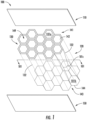
- FIG. 1 shows an exploded view of composite panel 100 according to one or more embodiments described herein.
- the composite panel 100 generally comprises a core structure 120 and a composite face sheet 110 bonded to a first side of the core structure 120.
- the first side is also referred to as the top side 141.
- the composite panel 100 may further comprise a composite back sheet 150 bonded to a second side of the core structure 120 and opposite the first side.
- the second side is also referred to as the bottom side 143, which is opposite the top side 141.
- the core structure 120 may also comprise a cross-sectional geometry 101 that is nonuniform in a height direction between the top face 142 of top side 141 and the bottom face 144 of the bottom side 143.
- a cross-sectional geometry 101 that is nonuniform in a height direction between the top face 142 of top side 141 and the bottom face 144 of the bottom side 143.
- Such a configuration can provide a top face 142 of the core structure 120, a bottom side 143 of the core structure 120, or a combination thereof to produce greater bonding with the composite face sheet 110, the composite back sheet 150, or a combination thereof where present while also producing a lighter composite panel 100 compared to a completely solid composite material.
- the composite face sheet 110, the composite back sheet 150, and the core structure 120 can comprise a combination of different materials to facilitate structural and mechanical requirements for the composite panel 100.
- the composite face sheet 110 and the composite back sheet 150 can comprise any composite material, such as a ceramic matrix composite (also referred to as "CMCs").
- CMCs ceramic matrix composite
- Composite materials generally comprise a fibrous reinforcement material embedded in matrix material. The reinforcement material serves as a load-bearing constituent of the composite material, while the matrix of a composite material serves to bind the fibers together and act as the medium by which an externally applied stress is transmitted and distributed to the fibers.
- CMCs are well suited for structural applications because of their toughness, thermal resistance, high-temperature strength, and chemical stability.
- Such composites may have high strength-to-weight ratio that renders them attractive in applications in which weight is a concern, such as in aeronautic applications. Further, their stability at high temperatures renders CMCs very suitable in applications in which components are in contact with a high-temperature gas, such as within a gas turbine engine.
- Exemplary CMC materials may include silicon carbide (SiC), silicon, silica, carbon, or alumina matrix materials and combinations thereof. Ceramic fibers may be embedded within the matrix, such as oxidation stable reinforcing fibers including monofilaments like sapphire and silicon carbide (e.g., Textron's SCS-6), as well as rovings and yarn including silicon carbide (e.g., Nippon Carbon's NICALON ® , Ube Industries' TYRANNO ® , and Dow Corning's SYLRAMIC ® ), alumina silicates (e.g., 3M's Nextel 440 and 480), and chopped whiskers and fibers (e.g., 3M's Nextel 440 and SAFFIL ® ), and optionally ceramic particles (e.g., oxides of Si, Al, Zr, Y, and combinations thereof) and inorganic fillers (e.g., pyrophyllite, wollastonite, mica, tal
- bundles of the fibers are formed as a reinforced tape, such as a unidirectional reinforced tape.
- a plurality of the tapes may be laid up together (e.g., as plies) to form a preform component.
- the bundles of fibers may be impregnated with a slurry composition prior to forming the preform (e.g., prepreg plies) or after formation of the preform.
- the preform may then undergo thermal processing, such as a cure or burn-out to yield a high char residue in the preform, and subsequent chemical processing, such as melt-infiltration with silicon, to arrive at a component formed of a CMC material having a desired chemical composition.
- the CMC material may be formed as, e.g., a carbon fiber cloth rather than as a tape.
- the core structure 120 may comprise a different material compared to the composite face sheet 110 or the composite back sheet 150.
- the core structure 120 may be a material that is less dense than the material of the composite face sheet 110 or the composite back sheet 150. However, even when the material of the core structure 120 is different, it is compatible with the composite face sheet 110 and the composite back sheet 150 to produce a sufficient bond between the components, including in extreme operating conditions such as high temperatures.
- the core structure 120 may include silicon, silicon carbide, alumina, carbon, or aluminosilicates, or combinations thereof.
- the core structure 120 comprises a plurality of hollow cells 130 defined by a plurality of walls 132 extending from a top face 142 on a top side 141 to a bottom face 144 on a bottom side 143.
- Each of the plurality of hollow cells 130 that form the core structure 120 can extend in a parallel direction with one another.
- each top face 142 for each of the plurality of hollow cells 130 may be planar with one another so that the top side 141 of the core structure 120 comprises a substantially flat plane comprising a plurality of top faces 142 from the plurality of hollow cells 130.
- each bottom face 144 for each of the plurality of hollow cells 130 may be planar with one another so that the bottom side 143 of the core structure 120 comprises a substantially flat plane comprising a plurality of bottom faces 144 from the plurality of hollow cells 130.
- the top faces 142 and the bottom faces 144 may be parallel with one another such the composite face sheet 110 being bonded to the top side 141 of the core structure 120 will be parallel with the composite back sheet 150 being bonded to the bottom side 143 of the core structure 120.
- the core structure 120 in FIG. 1 is illustrated as having a plurality of hollow cells 130 that are parallel with one another, are the same length as one another, and comprise a top side 141 parallel with a bottom side 143, it should be appreciated that a variety of alternative or additional configurations may also be realized within the scope of this disclosure.
- the plurality of hollow cells 130 may comprise different lengths, may comprise different orientations, may produce top sides 141 and bottom sides 143 that are not planar or not parallel with one another, or any combination thereof.
- the plurality of walls 132 of the plurality of hollow cells 130 define the shape, and more specifically, the cross-sectional geometry 101, of each of the plurality of hollow cells 130. That is, the plurality of walls 132 create a partially closed structure (i.e., enclosed by the plurality of walls 132 on the side but potentially open on the ends at the top face 142 or the bottom face 144) to define a hollow interior 149 to form a cross-sectional geometry 101 for each of the plurality of cells.
- the cross-sectional geometry 101 refers to the open, or closed, space between the plurality of walls 132 at any point along the length of any individual cell.
- each cell 130 has a top cross-sectional geometry 101a at its top face 142 at the top side 141 of the core structure 120, and a bottom cross-sectional geometry 101b at its bottom face 144 at the bottom side 143 of the core structure 120.
- the plurality of walls 132 may be brought together to form the plurality of hollows cells 130 using a variety of different techniques.
- the plurality of walls 132 may be unitarily formed, monolithically formed, or unitarily and monolithically formed.
- the cross-sectional geometry 101 can comprise a variety of different shapes within each of the plurality of hollow cells 130.
- the cross-sectional geometry 101 of each hollow cell 130 may be a hexagon.
- the plurality of hollow cells 130 may have cross-sectional geometries 101 that are different, e.g., where the cross-sectional geometry 101 is one of a hexagon, circle, square, or a triangle in non-limiting examples.
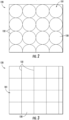
- each of the plurality of hollow cells 130 may have a substantially circular shape, such as shown in FIG. 2 .
- each of the plurality of hollow cells 130 may have a substantially square or rectangular shape, such as shown in FIG. 3 .
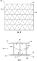
- each of the plurality of hollow cells 130 may have a substantially triangular shape, such as an equilateral triangle shape, such as illustrated in FIG. 4 .
- FIGS. 2-4 a variety of other exemplary cross-sectional geometries 101 are illustrated that can be utilized in the composite panel 100 illustrated in FIG. 1 .
- each of the plurality of hollow cells 130 may have a substantially circular shape, such as shown in FIG. 2 .
- each of the plurality of hollow cells 130 may have a substantially square or rectangular shape, such as shown in FIG. 3 .
- each of the plurality of hollow cells 130 may have a substantially triangular shape, such as an equilateral triangle shape, such as illustrated in FIG. 4 .
- each of the plurality of hollow cells 130 generally comprise a similar shape
- the plurality of hollow cells 130 may not all comprise the same general shape as one another.
- a plurality of hollow cells 130 may comprise one or more hollow cells 130 having a substantially hexagonal shape, one or more hollow cells 130 having a circular shape, one or more hollow cells 130 having a square shape, or one or more hollow cells 130 having a triangular shape. While the plurality of hollow cells 130 are illustrated as having substantially similar sizes in the respective embodiments illustrated in FIGS. 2-4 , in some embodiments, the plurality of hollow cells 130 may vary in size with respect to one another.
- the cross-sectional geometry 101 may have an open cross-sectional area that is smaller, larger, or have a different shape at one or more locations along at least a portion of one of the plurality of hollow cells 130.
- FIGS. 5-12 Various exemplary configurations of cross-sectional geometries 101 that are nonuniform are illustrated in FIGS. 5-12 .
- the cross-sectional geometry 101 from the top face 142 to the bottom face 144 is nonuniform for one or more of the plurality of hollow cells 130.
- the cross-sectional geometry 101 may have an open cross-sectional area that is smaller, larger, or have a geometry that is a different shape at one or more locations along at least one of the plurality of hollow cells 130 to provide an overall cross-sectional geometry 101 that is nonuniform between its top side 141 and bottom side 143. Having a cross-sectional geometry 101 that is nonuniform can facilitate enhanced bonding with composite face sheet 110 or the composite back sheet 150, such as by providing additional material or surface area on a top side 141 or bottom side 143 of the core structure 120, while still reducing the amount of overall material used in the core structure 120 via the overall configuration of the plurality of hollow cells 130.
- each of the plurality of cells will have a top cross-sectional geometry 101a at its top face 142 and a bottom cross-sectional geometry 101b at its bottom face 144.
- the top cross-sectional geometry 101a and the bottom cross-sectional geometry 101b can be different from one another (e.g., one open cross-sectional area that is smaller than the other) to provide a cross-sectional geometry of the hollow cell that is nonuniform.
- the cross-sectional geometry 101 can thereby comprise a variety of different configurations at different locations. As illustrated in FIG.
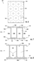
- At least one of the plurality of hollow cells 130 of the composite panel 100 has a midspan cross-sectional geometry 101c at a location between the top face 142 and the bottom face 144 that has an open cross-sectional area smaller than that at the top face 142 or at the bottom face 144.
- midspan refers to any location between the top faced 142 and the bottom face 144, whether it is halfway therebetween or skewed towards one face.
- the midspan cross-sectional geometry 101c has an open cross-sectional area that is smaller than that at both the top cross-sectional geometry 101a and the bottom cross-sectional geometry 101b.
- Such embodiments provide an hourglass-type configuration within the hollow cell 130.
- each of the plurality of hollow cells 130 has a closed face 146 and an open face 148.
- closed face refers to the walls 132 of the core structure 120 enclosing (e.g., capping) the hollow cell 130 at one of the top face 142 or the bottom face 144.
- the closed face e.g., at the bottom face 144 in FIG. 5
- the closed face would have an open cross-sectional area for the bottom cross-sectional geometry 101b that is smaller than (i.e., zero) than the open cross-sectional area for the top cross-sectional geometry 101a of the top face 142 that is an open face.
- the closed face 146 is adjacent to the bottom face 144, e.g., on the end with the horizontal wall 132b.
- the term "open face” refers to the cell 130 being open on either the top face 142, the bottom face 144, or both.
- the "open face” of the hollow cell 130 refers to the top face 142 or the bottom face 144 as having at least some open cross-sectional area between the vertical walls 132a of the one or more walls 132.
- the open face 148 is on the opposite end of the vertical walls 132a where there is no horizontal wall 132b adjacent the composite face sheet 110.
- Each of the plurality of hollow cells 130 includes a hole 138.
- the hole 138 can be configured and utilized for removing debris or for providing airflow. For example, if the composite panel 100 is manufactured via binder jet printing, de-powdering may be necessary (e.g., removing loose powder from the hollow interior 149 of the hollow cell 130). The hole 138 would allow for the de-powdering, e.g., the removal of the powder resulting from binder jet printing.
- each hollow cell 130 may additionally or alternatively be located on any of the one or more walls 132 of each hollow cell 130. Furthermore, the hole 138 may also be located off-center of each hollow cell 130. The hole 138 may additionally be in a different location in each hollow cell 130.
- FIG. 5 illustrates each top face 142 being an open face 148 and each bottom face 144 being a closed face 146
- a variety of configurations within the composite panel 100 may alternatively or additionally be realized using a combination of open faces 148 and closed faces 146, or incorporation of partially open bottom faces 144' as illustrated in FIG. 6 .
- FIG. 7 a cross-sectional slice of the core structure 120 with the plurality of hollow cells 130 is shown with the one or more walls 132 arranged such that openings for the hollow cells 130 are in an interspersed pattern (e.g., alternating or intermittent pattern of open faces 148 and closed faces 146).
- an interspersed pattern e.g., alternating or intermittent pattern of open faces 148 and closed faces 146.
- the closed face 146 of each hollow cell 130 is in the alternating pattern with the open face 148 of a hollow cell 130 adjacent thereto, top to bottom and vice versa as a non-limiting example.
- multiple top faces 142 in adjacent hollow cells 130 could have closed faces 146, which may in turn be adjacent hollow cells with bottom faces 144 being closed faces 146 and that would still be considered interspersed.
- any suitable repeating pattern or random placement can be utilized to intersperse.
- the cross-sectional illustration depicts a first closed face 146a on the top face 142 and a first open face 148a on the bottom face 144 in a first hollow cell 130a; a second open face 148b on the top face 142 and a second closed face 146b in a second cell 130b; a third closed face 146c on the top face 142 and a third open face 148c in a third cell 130c; and a fourth open face 148d on the top face 142 and a fourth closed face 146d in a fourth cell 130d.
- the composite face sheet 110 and the composite back sheet 150 are also shown sandwiching the core structure 120.
- Such embodiments of interspersed (alternating or intermittent) open faces 148 and closed faces 146 on one or both of the top side 141 and the bottom side 143 of the core structure 120 can provide a composite panel 100 that still provides reduced weight and cost by lowering the amount of material used in the core structure 120, but provides enhanced bonding with the composite face sheet 110 or composite back sheet 150 via the additional material at their respective interfaces with the core structure 120.
- each of the one or more walls 132 may also include a tapered interface 152 along the second open face 148b.
- the tapered interface 152 comprises additional material from the core structure 120 that extends inwards from at least one of the plurality of walls 132.
- the tapered interface 152 may thereby provide additional surface area for bonding with a composite face sheet 110 or composite back sheet 150, while also providing additional structural support at the interface (e.g., by distributing stress along the tapered interface 152 instead of a concentrating stress at a 90 degree joint).
- the tapered interface 152 extends on each side of the one or more walls 132 and includes a curved configuration.
- the tapered interface 152 may have a constant or non-constant radius as it extends from the one or more walls 132.
- tapered interfaces 152 may be utilized in a variety of configurations, such as with closed faces 146 or open faces 148, at one or both of the top faces 142 or bottom faces 144, and within each hollow cell 130 or within only some hollow cells 130.
- each hollow cell 130 further includes the tapered interface 152 on each side of the one or more walls 132.
- the tapered interface 152 of each of the one or more walls 132 is at least part of the closed face 146, e.g., the tapered interface 152 of each of the one or more walls 132 extends such that it touches the adjacent tapered interface 152, and at least partially becomes the closed face 146.
- each of the one or more walls 132 adjacent the closed face 146 further includes a first tapered interface 152a extending on either side of the one or more walls 132. Additionally, the first tapered interface 152a of each of the one or more walls 132 extends such that it touches an adjacent first tapered interface 152a, making the closed face 146 along the bottom face 144.
- Each of the one or more walls 132 may also have a second tapered interface 152b on the open face 148, such that each end of each of the one or more walls 132 has a tapered interface 152.
- FIG. 11 a cross-sectional slice of the core structure 120 is illustrated with the plurality of hollow cells 130 shown having top faces 142 and bottom faces 144 in an alternating pattern (e.g., similar to FIG. 7 ), with each of the one or more walls 132 further including the tapered interface 152.
- the first cell 130a has a first closed face 146a on the top face 142 and a first open face 148a on the bottom face 144.
- the second cell 130b there is a second closed face 146b on the bottom face 144 and the second open face 148b on the top face 142.
- Each of the one or more walls includes the tapered interface 152, with adjacent tapered interfaces 152 connecting and creating the first closed face 146a and the second closed face 146b. While certain embodiments are illustrated herein, the tapered interfaces may be present in any ordered or random pattern within the composite panel 100.
- each of the plurality of hollow cells 130 is illustrated having the first open face 148a on the top face 142 and the second open face 148b on the bottom face 144.
- each of the one or more walls 132 has the first tapered interface 152a with a curve on either side of the one or more walls 132 along the top face 142 and a curve on either side of the one or more walls 132 along the second tapered interface 152b on the side of the bottom face 144.
- FIG. 12 illustrates each interface with the composite face sheet 110 and composite back sheet 150 has having a substantially similar profile, the respective interfaces may also vary in profile, shape, or size, such as based on a predetermined or predicted loading conditions.
- the method generally comprises manufacturing a core structure 120 in step 210 and bonding a composite face sheet 110 to the core structure 120 in step 220.
- the core structure generally comprises a plurality of hollow cells 130 defined by a plurality of walls 132 extending from a top face 142 on a top side 141 to a bottom face 144 on a bottom side 143 opposite the top side 141.
- the core structure 120 further comprises a cross-sectional geometry 101 from the top face 142 to the bottom face 144 is nonuniform for one or more of the plurality of hollow cells 130.
- the plurality of hollow cells 130 can comprise a top cross-sectional geometry 101a at the top face142 that has a top cross-sectional area smaller than a bottom cross-sectional area of the bottom cross-sectional geometry 101b at the bottom face 144.
- manufacturing the core structure 120 in step 210 comprises additively manufacturing the plurality of walls 132 such as via a binder jet or similar process to produce an additively manufactured core structure.
- Additive manufacturing the plurality of walls 132 can comprise building some or all of the plurality of walls 132 in a layer-by-layer manner, such as by using a powder feedstock material.
- additive manufacturing the plurality of walls 132 can result in a residual amount of loose unconsolidated powder feedstock in the hollow interior 139 of each of the plurality of hollow cells 130.
- the method 200 may further comprise removing the powder feedstock from at least one of the plurality of hollows cells 130.
- the powder feedstock may be poured or vacuumed out of an open face 148 of the hollow cell 130.
- the core structure 120 additively manufactured in step 210 may comprise a hole 138 or open face in at least one of the top face 142 or the bottom face 144.
- the hole 138 or open face may facilitate for the removal of powder feedstock from a potentially otherwise enclosed hollow interior 149.
- core structures 120 having complex geometries may be manufactured using additive manufacturing, along with having a cross-sectional geometry that is nonuniform (e.g., having a closed face 146) to facilitate enhanced bonding with composite face sheets 110 or composite back sheets 150, while still allowing for the removal of powder feedstock from the hollow interior 149.
- Removal the powder feedstock can further allow for the unused powder feedstock to be recycled and used to make core structures 120 for additional composite panels 100 or other parts of the composite panel 100.
- the core structure 120 may be ready for use in the composite panel 100, or may require one or more further intermediate processing steps.
- the core structure 120 may be in a green state after additive manufacturing.
- the method 200 may further comprise curing the core structure 120 to remove moister or sintering the core structure 120.
- the method further comprises bonding the composite face sheet 110 to the top side 141 of the core structure 120 in step 220.
- Bonding may comprise any suitable process to mechanically integrate the composite face sheet 110 with the core structure 120.
- bonding in step 220 may comprise adhesive bonding.
- bonding in step 220 may comprise one or more manufacturing steps utilized in manufacturing ceramic matrix composites, such as infiltration of the ceramic material or curing.
- the method 200 may further comprise bonding a composite back sheet 150 to the bottom side 143 of the core structure 120 in step 230.
- the composite back sheet 150 may be bonded to the core structure 120 at the same time, afterwards, or before the composite face sheet 110 is bonded to the core structure 120.
- Such embodiments may thereby produce a composite panel 100 with a composite face sheet 110 and a composite back sheet 150 on opposite sides of the core structure 120.
- the composite panel 100 as disclosed and described herein may be used in a variety of industrial machines, including but not limited to one or more components of turbomachines. Moreover, the composite panel 100 disclosed and described herein can provide a more cost-effective, lighter, and potentially stronger alternative to solid composite structures. However, the composite panels disclosed and described herein further provides enhanced bonding between the core structure 120 and the composite face sheet 110 or between the core structure 120 and the composite back sheet 150.
- a composite panel comprising a core structure comprising a plurality of hollow cells, the plurality of hollow cells defined by a plurality of walls extending from a first face to a second face, wherein a cross-sectional geometry from the first face to the second face is nonuniform for at least one of the plurality of hollow cells; and a composite face sheet bonded to the core structure at the first face.
- first cells of the plurality of hollow cells comprise a first open cross-sectional area at the first face that is larger than a second open cross-sectional area at the second face.
- second cells of the plurality of hollow cells comprise a first open cross-sectional area at the first face that is smaller than a second open cross-sectional area at the second face.
- composite panel of any clause herein further comprising a composite back sheet bonded to the core structure at the second face.
- a method of manufacturing a composite panel comprising manufacturing a core structure comprising a plurality of hollow cells defined by a plurality of walls extending from a first face to a second face, wherein a cross-sectional geometry from the first face to the second face is nonuniform for one or more of the plurality of hollow cells; and bonding a composite face sheet to the core structure at the first face.
- both the composite face sheet and the composite back sheet each comprise a ceramic matrix composite.
- manufacturing the core structure comprises additively manufacturing the plurality of walls
- At least a first plurality of hollow cells each comprise a first open cross-sectional area at the first face that is smaller than a second open cross-sectional area at the second face.
- a second plurality of hollow cells each comprise a first open cross-sectional area at the first face that is larger than a second open cross-sectional area at the second face.
Landscapes
- Engineering & Computer Science (AREA)
- Ceramic Engineering (AREA)
- Chemical & Material Sciences (AREA)
- Manufacturing & Machinery (AREA)
- Materials Engineering (AREA)
- Laminated Bodies (AREA)
Applications Claiming Priority (1)
| Application Number | Priority Date | Filing Date | Title |
|---|---|---|---|
| US18/162,919 US20240253324A1 (en) | 2023-02-01 | 2023-02-01 | Composite panels and methods for making the same |
Publications (1)
| Publication Number | Publication Date |
|---|---|
| EP4410532A1 true EP4410532A1 (fr) | 2024-08-07 |
Family
ID=89771746
Family Applications (1)
| Application Number | Title | Priority Date | Filing Date |
|---|---|---|---|
| EP24154428.7A Pending EP4410532A1 (fr) | 2023-02-01 | 2024-01-29 | Panneaux composites et leurs procédés de fabrication |
Country Status (3)
| Country | Link |
|---|---|
| US (1) | US20240253324A1 (fr) |
| EP (1) | EP4410532A1 (fr) |
| CN (1) | CN118418535A (fr) |
Citations (6)
| Publication number | Priority date | Publication date | Assignee | Title |
|---|---|---|---|---|
| US20180319121A1 (en) * | 2017-05-08 | 2018-11-08 | The Boeing Company | Composite structure assembly having a conformable core |
| US20190086082A1 (en) * | 2017-09-19 | 2019-03-21 | Hexcel Corporation | Thermal panel |
| US20200114573A1 (en) * | 2018-10-16 | 2020-04-16 | Divergent Technologies, Inc. | Methods and apparatus for manufacturing optimized panels and other composite structures |
| US10843434B2 (en) * | 2015-06-22 | 2020-11-24 | Sikorsky Aircraft Corporation | Core material for composite structures |
| US20210324794A1 (en) * | 2018-08-08 | 2021-10-21 | General Electric Company | Acoustic cores with sound-attenuating protuberances |
| WO2021260286A1 (fr) * | 2020-06-23 | 2021-12-30 | Safran | Panneau acoustique et procede de fabrication associe |
Family Cites Families (12)
| Publication number | Priority date | Publication date | Assignee | Title |
|---|---|---|---|---|
| US6199342B1 (en) * | 1998-02-17 | 2001-03-13 | Newcourt, Inc. | Method for forming structure suitable for use as a core member |
| JP3938265B2 (ja) * | 1999-01-18 | 2007-06-27 | 横浜ゴム株式会社 | 緩衝装置 |
| US6472043B1 (en) * | 1999-01-18 | 2002-10-29 | The Yokohama Rubber Co., Ltd. | Shock absorber |
| US8097106B2 (en) * | 2007-06-28 | 2012-01-17 | The Boeing Company | Method for fabricating composite structures having reinforced edge bonded joints |
| GB201209658D0 (en) * | 2012-05-31 | 2012-07-11 | Rolls Royce Plc | Acoustic panel |
| FR3018719B1 (fr) * | 2014-03-24 | 2016-04-29 | Airbus Operations Sas | Procede de consolidation d'elements en materiau composite pour former une piece en materiau composite comprenant une cavite debouchante et noyau utilise pour la mise en oeuvre dudit procede |
| US9476359B2 (en) * | 2014-04-11 | 2016-10-25 | Rohr, Inc. | Acoustic liner |
| US10174675B2 (en) * | 2015-12-30 | 2019-01-08 | General Electric Company | Acoustic liner for gas turbine engine components |
| US11059559B2 (en) * | 2018-03-05 | 2021-07-13 | General Electric Company | Acoustic liners with oblique cellular structures |
| US10960637B2 (en) * | 2018-07-02 | 2021-03-30 | The Boeing Company | Core structures for composite panels, aircraft including the same, and related methods |
| CN112743933B (zh) * | 2020-12-02 | 2022-12-27 | 郑州大学 | 一种双层自旋折纸蜂窝夹层吸能材料及其制备方法 |
| US20230286640A1 (en) * | 2022-03-10 | 2023-09-14 | General Electric Company | Acoustic absorber for a gas turbine engine |
-
2023
- 2023-02-01 US US18/162,919 patent/US20240253324A1/en not_active Abandoned
-
2024
- 2024-01-29 EP EP24154428.7A patent/EP4410532A1/fr active Pending
- 2024-02-01 CN CN202410141210.6A patent/CN118418535A/zh active Pending
Patent Citations (6)
| Publication number | Priority date | Publication date | Assignee | Title |
|---|---|---|---|---|
| US10843434B2 (en) * | 2015-06-22 | 2020-11-24 | Sikorsky Aircraft Corporation | Core material for composite structures |
| US20180319121A1 (en) * | 2017-05-08 | 2018-11-08 | The Boeing Company | Composite structure assembly having a conformable core |
| US20190086082A1 (en) * | 2017-09-19 | 2019-03-21 | Hexcel Corporation | Thermal panel |
| US20210324794A1 (en) * | 2018-08-08 | 2021-10-21 | General Electric Company | Acoustic cores with sound-attenuating protuberances |
| US20200114573A1 (en) * | 2018-10-16 | 2020-04-16 | Divergent Technologies, Inc. | Methods and apparatus for manufacturing optimized panels and other composite structures |
| WO2021260286A1 (fr) * | 2020-06-23 | 2021-12-30 | Safran | Panneau acoustique et procede de fabrication associe |
Also Published As
| Publication number | Publication date |
|---|---|
| CN118418535A (zh) | 2024-08-02 |
| US20240253324A1 (en) | 2024-08-01 |
Similar Documents
| Publication | Publication Date | Title |
|---|---|---|
| EP3401506B1 (fr) | Procédés de formation de microcanaux dans des composants de cmc | |
| EP4414345A1 (fr) | Panneaux composites et leurs procédés de fabrication | |
| US10569481B2 (en) | Shaped composite ply layups and methods for shaping composite ply layups | |
| EP2006487B1 (fr) | Procédé pour la fabrication d'articles en CMC dotés de petites caractéristiques complexes | |
| JP5519905B2 (ja) | 小さくて複雑な特徴部を有するcmc物品 | |
| EP3574263B1 (fr) | Ensemble de trajet d'écoulement pour un moteur de turbine à gaz | |
| US20090004425A1 (en) | Ceramic Matrix Composite Structure having Fluted Core and Method for Making the Same | |
| EP4631722A1 (fr) | Panneau composite et procédé de fabrication | |
| US20250305599A1 (en) | Composite tube assemblies and method of manufacturing | |
| US20240253324A1 (en) | Composite panels and methods for making the same | |
| EP4442454A1 (fr) | Structure tubulaire composite en céramique | |
| US20250303662A1 (en) | Composite panels having an integrated attachment feature and methods for making the same | |
| US20250303663A1 (en) | Composite panel assemblies having interlocking joints and methods for making the same | |
| US20260085014A1 (en) | Method for bonding cmc facesheets to ceramic cores | |
| US20260085016A1 (en) | Method for bonding cmc facesheets to ceramic cores | |
| US12466107B2 (en) | Granulated feedstock for additively manufacturing ceramic components | |
| US20250250208A1 (en) | Ceramic composite component | |
| US20250276941A1 (en) | Method for repairing ceramic composite components | |
| EP4653689A1 (fr) | Assemblage de chambre de poussée | |
| CA2612014A1 (fr) | Methode de fabrication d'articles en cmc comportant des petits dispositifs complexes | |
| CN120829318A (zh) | 用于限制陶瓷基复合材料部件中孔隙形成的系统和方法 |
Legal Events
| Date | Code | Title | Description |
|---|---|---|---|
| PUAI | Public reference made under article 153(3) epc to a published international application that has entered the european phase |
Free format text: ORIGINAL CODE: 0009012 |
|
| STAA | Information on the status of an ep patent application or granted ep patent |
Free format text: STATUS: THE APPLICATION HAS BEEN PUBLISHED |
|
| AK | Designated contracting states |
Kind code of ref document: A1 Designated state(s): AL AT BE BG CH CY CZ DE DK EE ES FI FR GB GR HR HU IE IS IT LI LT LU LV MC ME MK MT NL NO PL PT RO RS SE SI SK SM TR |
|
| STAA | Information on the status of an ep patent application or granted ep patent |
Free format text: STATUS: REQUEST FOR EXAMINATION WAS MADE |
|
| 17P | Request for examination filed |
Effective date: 20250206 |