EP4410630A1 - Automatische kupplung - Google Patents
Automatische kupplung Download PDFInfo
- Publication number
- EP4410630A1 EP4410630A1 EP23154770.4A EP23154770A EP4410630A1 EP 4410630 A1 EP4410630 A1 EP 4410630A1 EP 23154770 A EP23154770 A EP 23154770A EP 4410630 A1 EP4410630 A1 EP 4410630A1
- Authority
- EP
- European Patent Office
- Prior art keywords
- signal
- coupling
- actuator
- latching
- receipt
- Prior art date
- Legal status (The legal status is an assumption and is not a legal conclusion. Google has not performed a legal analysis and makes no representation as to the accuracy of the status listed.)
- Granted
Links
Images


Classifications
-
- B—PERFORMING OPERATIONS; TRANSPORTING
- B61—RAILWAYS
- B61G—COUPLINGS; DRAUGHT AND BUFFING APPLIANCES
- B61G3/00—Couplings comprising mating parts of similar shape or form which can be coupled without the use of any additional element or elements
- B61G3/22—Couplings comprising mating parts of similar shape or form which can be coupled without the use of any additional element or elements with coupling heads rigidly connected by locks consisting of pivoted latches
- B61G3/26—Control devices, e.g. for uncoupling
-
- B—PERFORMING OPERATIONS; TRANSPORTING
- B61—RAILWAYS
- B61G—COUPLINGS; DRAUGHT AND BUFFING APPLIANCES
- B61G5/00—Couplings for special purposes not otherwise provided for
- B61G5/02—Couplings for special purposes not otherwise provided for for coupling articulated trains, locomotives and tenders or the bogies of a vehicle; Coupling by means of a single coupling bar; Couplings preventing or limiting relative lateral movement of vehicles
-
- B—PERFORMING OPERATIONS; TRANSPORTING
- B61—RAILWAYS
- B61D—BODY DETAILS OR KINDS OF RAILWAY VEHICLES
- B61D17/00—Construction details of vehicle bodies
- B61D17/04—Construction details of vehicle bodies with bodies of metal; with composite, e.g. metal and wood body structures
- B61D17/20—Communication passages between coaches; Adaptation of coach ends therefor
- B61D17/22—Communication passages between coaches; Adaptation of coach ends therefor flexible, e.g. bellows
-
- B—PERFORMING OPERATIONS; TRANSPORTING
- B61—RAILWAYS
- B61G—COUPLINGS; DRAUGHT AND BUFFING APPLIANCES
- B61G3/00—Couplings comprising mating parts of similar shape or form which can be coupled without the use of any additional element or elements
- B61G3/22—Couplings comprising mating parts of similar shape or form which can be coupled without the use of any additional element or elements with coupling heads rigidly connected by locks consisting of pivoted latches
- B61G3/24—Latch-locking devices
Definitions
- the present invention relates to a system for coupling a first coach of a train to a second coach of the train, the system comprising a first automatic coupler, wherein the first automatic coupler is mountable at an end of the first coach, wherein the first automatic coupler provides for a mechanical coupling to a second mechanical coupler mountable at the second coach, wherein the first automatic coupler comprises a first coupling actuator and a first locking mechanism, and wherein the first coupling actuator during operation of the system drives the first locking mechanism between a locked state and unlocked state; a first bellows, wherein the first bellows provides protection of a passenger or an object moving from the first coach to the second coach, wherein the first bellows comprises a first mounting frame, a first coupling frame, and a first latching mechanism at the first coupling frame, wherein the first mounting frame is fixable to a wall of the first coach, wherein the first coupling frame is releasably couplable by the first latching mechanism to a second coupling frame of the second
- the number of coaches in a train needs to be increased or decreased. Matching the number of coaches to the number of expected passengers reduces overall energy consumption of a railway system. This in particular applies to trains used for local public transport.
- train systems wherein two complete trains may be connected or divided using automatic coupling and uncoupling.
- two trains When two trains are coupled they run as a single train to accommodate more passengers during peak hours. While easy to couple or decouple, these systems carry many facilities of the trains twice or more during peak hour operation. E.g., each of the trains coupled has typically two driver's cabs.
- a single train for increasing or decreasing the number of coaches is driven to the depot or station, the train is separated in the middle and an intermediate coach is added or removed from the train.
- Coupling and uncoupling an intermediate coach from a single train according to the prior still to a certain extend is a manual operation.
- automatic couplers are disclosed which allow to automatically couple or decouple the coaches mechanically, I.e. to provide the required mechanical connection such that one coach pulls or pushes the other.
- the prior art coupling and uncoupling requires manual effort for coupling and uncoupling the bellows. This means for each coupling and uncoupling operation an operator to couple or uncouple the two bellows of the coaches involved. This is a time-consuming and costly way to increase or decrease the number of coaches of a single train.
- the first bellows in the system of a type mentioned above comprises a first latching actuator, wherein the first latching actuator during operation of the system drives the first latching mechanism between a latched state and an unlatched state; wherein the controller is operatively coupled to the first latching actuator, wherein the controller is arranged to generate an unlatch signal upon receipt of the uncoupling instruction, send the unlatch signal to the first latching actuator prior to sending the uncoupling signal to the first coupling actuator, generate at latching signal upon receipt of the coupling instruction, and send the latching signal to the first latching actuator after sending the coupling signal to the first coupling actuator; and wherein the first latching actuator upon receipt of an unlatch signal drives the first latching mechanism from the latched state to the unlatched state, and wherein the first latching actuator upon receipt of the latching signal drives the first latching mechanism from the unlatched state to the latched state.
- the system according to the present invention comprises those components to be attached to the first coach of the train and to be integrated into the train, which components enable an automated coupling and uncoupling of the first coach from a second coach, the system does not comprise the first coach as such.
- the general idea of a system according to the present invention to automatize a coupling and uncoupling of the first coach of the train to and from the second coach by using an automatic coupler as well as an automated latching and unlatching of the first bellows to be attached to the first coach from a second bellows to be attached to the second coach.
- the first coupling actuator drives the first locking mechanism of the first automatic coupler upon receipt of the coupling signal or the uncoupling signal.
- One of the basic concepts of the present invention is that the controller during a coupling operation in a first step completes automatic coupling of the first automatic coupler with the second automatic coupler before initiating the latching operation. Consequently, the controller sends the latching signal to the first latching actuator for latching the first bellows to the second bellows only after it has generated and sent the coupling signal.
- the controller sends the unlatching signal to the first latching actuator for unlatching the first bellows from the second bellows before generating and sending the coupling signal to the first automated coupler.
- an automatic coupler forming part of a system according to the present invention is known from the prior art in many embodiments.
- Automatic couplers enable mechanical coupling of one coach to another coach using electrical, pneumatic or hydraulic signals for locking and unlocking.
- An automatic coupler is operated without any manual operation at the coupler.
- the first automatic coupler has a first coupling actuator and a first locking mechanism, wherein the coupling actuator drives the first locking mechanism between a locked state and an unlocked state. In the locked state, the first locking mechanism provides at least a frictional connection or a positive fit to the second automatic coupler and in the unlocked state this frictional connection or positive fit is released.
- the first automatic coupler is selected from a group comprising a Buckeye coupler, a Janney coupler, a MCB coupler, an ARA coupler, an AAR coupler, an APTA coupler, a Bazeley coupler, a Henricot coupler, a Willison coupler, a SA3 coupler, an Unicoupler, an Intermat coupler, a C-Akv coupler, a Z-AK coupler and a Unilink coupler or a combination thereof.
- the first automatic coupler is a Multi-Function Coupler (MFC) providing all connections between the first coach and the second coach without human intervention in contrast to semi-automatic couplers, which just handle the mechanical aspects.
- MFC Multi-Function Coupler
- the Multi-Function Coupler in addition to the mechanical coupling provides a coupling of electrical and pneumatic or hydraulic supplies.
- the first automatic coupler is a Multi-Function Coupler (MFC) selected from a group consisting of a Westinghouse H2C coupler, a WABCO N-Type coupler, a Tomlinson coupler, a Scharfenberg coupler, an Automatic Buffing Contact (ABC) coupler, a Dellner coupler, a Ward Coupler, a Wedgelock coupler, a Schwab coupler and a Shibata coupler or a combination thereof.
- MFC Multi-Function Coupler
- the first bellows comprises a mounting frame in order to mount the first bellows at the first coach. Further, the first bellows comprises a first coupling frame at an end opposite to the mounting frame, wherein the first coupling frame serves to connect the first bellows to a second coupling frame at a second bellows mountable at the second coach.
- the first bellows according to the present invention provides at least weather protection, pressure tightness or acoustic insulation. Bellows are known from the prior art according to multiple embodiments.
- the first bellows comprises a plurality of folds or corrugations made of a tarpaulin with a flexible web-shaped material.
- the first bellows comprises a first latching mechanism at the first coupling frame.
- the first latching mechanism interacts with a second coupling frame of the second bellows to provide at least a frictional connection or a positive fit.
- the first latching mechanism provides at least a frictional connection or a positive fit of the first coupling frame to the second coupling frame of the second bellows attached to the second coach.
- the controller according to the present invention is a device or a group of devices controlling the coupling and uncoupling processes.
- the controller generates and optionally receives signals to and from the plurality of components of the system in order to initiate and monitor certain steps of the automatic coupling and uncoupling process.
- At least one of the devices of the controller is an electrical or electronical device, preferably a digital device.
- the controller comprises a computer with a processor, wherein a software is executed on the processor.
- the controller consists of a single device, e.g., a computer.
- An embodiment, wherein the controller is provided by a single device is particular suitable once the signals to be transmitted are electrical signals, only and the actuators are electrical actuators, only.
- the controller comprises a first device, which first device is an electrical or electronical device, and a second device, which second device comprises a pneumatic or a hydraulic switch, which pneumatic or hydraulic switch is controllable by an electrical or pneumatic or hydraulic signal.
- the pneumatic or hydraulic switch is a solenoid valve opening and closing at least one fluid duct upon receipt of a signal
- At least one device of the controller is part of a train control management system.
- the coupling instruction is either a manually generated coupling instruction, e.g. by pushing an analog or virtual button at an operator's panel, or a machine generated coupling instruction generated by a sensor of the system.
- the uncoupling instruction is either a manually generated uncoupling instruction, e.g. by pushing an analog or virtual button at an operator's panel, or a machine generated uncoupling instruction generated by a sensor of the system.
- At least one of the uncoupling signal, the coupling signal, the unlatched signal and the latching signal is an electrical signal, a pneumatic signal or a hydraulic signal.
- the first bellows and the second bellows to be coupled to the first bellows are extendable and retractable. I.e. a distance between the first coupling frame and the first mounting frame is variable in order for the first bellows not to interfere with the automatic coupler during coupling or uncoupling process.
- a first motion actuator is arranged to vary the distance between the coupling frame and the first mounting frame automatically.
- the first bellows comprises a first motion actuator, wherein the first motion actuator is arranged to move the first coupling frame of the first bellows relatively to the first mounting frame between an extended position and a retracted position, wherein in the extended position a distance between the first coupling frame and the first mounting frame is larger than in the retracted position.
- the controller is operatively coupled to the first motion actuator, wherein the controller is arranged to generate a retract signal upon receipt of the uncoupling instruction, to send the retract signal to the first motion actuator after sending the unlatched signal to the first latching actuator and prior to sending the uncoupling signal to the first coupling actuator, to generate an extend signal upon receipt of the coupling instruction, and send the extend signal to the first motion actuator after sending the coupling signal to the first coupling actuator and prior to sending the latching signal to the first latching actuator.
- the first motion actuator upon receipt of the retract signal drives the coupling frame from the extended position to the retracted position
- the first motion actuator upon receipt of the extend signal drives the first coupling frame from the retracted position to the extended position.
- a retract signal during uncoupling is only send after the unlatched signal and prior to the uncoupling signal.
- the other way round during the coupling process the extend signal is only send after the coupling signal and prior to sending the latching signal. This way a threefold operation during coupling and uncoupling is well-timed.
- the first coupling actuator, the first latching actuator or the first motion actuator is selected from a group consisting of an electrical actuator, pneumatic actuator and a hydraulic actuator.
- the first automatic coupler comprises a first coupling sensor, which first coupling sensor is operatively coupled to the controller, wherein the first coupling sensor is arranged to sense whether the first locking mechanism is in the locked state and to generate a first coupled signal once the first locking mechanism is in the locked state, and wherein the controller is arranged to send the latching signal after receipt of the first coupled signal.
- the first bellows comprises a first latching sensor, which first latching sensor is operatively coupled to the controller, wherein the first latching sensor is arranged to sense whether the first latching mechanism is in the unlatched state and to generate a first unlatched signal once the first latching mechanism is in the unlatched state, and wherein the controller is arranged to send the uncoupling signal after receipt of the first unlatched signal.
- the first bellows comprises a first position sensor, which first position sensor is operatively coupled to the controller, wherein the first position sensor is arranged to sense whether the first bellows is in the extended position and to generate a first extended position signal once the first bellows is in the extended position, wherein the first position sensor is arranged to sense whether the first bellows is in the retracted position and to generate a first retracted position signal once the first bellows is in the retracted position, wherein the controller is arranged to send the latching signal after receipt of the first extended position signal, and wherein the controller is arranged to send the uncoupling signal after receipt of the first retracted position signal.
- This embodiment in a coupling operation allows to complete automatic coupling of the first automatic coupler with the second automatic coupler prior to moving the coupling frame of the first bellows into the extended position. Furthermore, this embodiment allows to complete motion of the first coupling frame to the extended position before latching is initiated.
- the controller is arranged upon receipt of the uncoupling instruction to generate and send the unlatched signal, to wait for the first unlatched signal from the first latching sensor, generate and send retract signal upon receipt of the first unlatched signal, wait for the first retracted position signal from the first position sensor, and generate and send the uncoupling signal upon receipt of the first retracted position signal; and upon receipt of the coupling instruction generate and send the coupling signal, wait for the first coupled signal from the first coupling sensor, generate and send the extend signal upon receipt of the first coupled signal, wait for the first extended position signal, and generate and send the latching signal upon receipt of the first extended position signal.
- controller controls the multiple set of actuators in a secure and reliable manner.
- the second automatic coupler is identical to the first automatic coupler.
- Optional features of the first automatic coupler are also optional features of the second automatic coupler, wherein the respective arrangements of the second automatic coupler are denoted by the term "second".
- the second bellows is identical to the first bellows.
- Optional features of the first bellows are also optional features of the second bellows, wherein the respective arrangements of the second bellows are denoted by the term "second".
- first and the second automatic coupler as well as the first and the second bellows are complementary with respect to each other in a sense that they can be coupled to each other.
- first and second automatic couplers as well as the first and second automatic bellows are mirror symmetrical with respect to a plane parallel to the first and second coupling frames.
- the system comprises a second automatic coupler, wherein the second automatic coupler is mountable at an end of the second coach, wherein the second automatic coupler provides for a mechanical coupling to the first mechanical coupler mountable at the first coach, wherein the second automatic coupler comprises a second coupling actuator and a second locking mechanism, and wherein the second coupling actuator during operation of the system drives the second locking mechanism between a locked state and an unlocked state.
- the system comprises a second bellows, wherein the second bellows provides protection of a passenger or an object moving from the first coach to the second coach, wherein the second bellows comprises a second mounting frame, a second coupling frame, and a second latching mechanism at the second coupling frame, wherein the second mounting frame is fixable to a wall of the second coach, wherein the second bellows is movable from an extended position to a retracted position, wherein the second coupling frame is releasably couplable by the second latching mechanism to a first coupling frame of the first bellows at the first coach, wherein the second bellows comprises a second latching actuator, and wherein the second latching actuator during operation of the system drives the second latching mechanism between a latched state and an unlatched state.
- the controller is operatively coupled to the second coupling actuator and the controller is operatively coupled to the second latching actuator.
- the controller is arranged to send the uncoupling signal to the second coupling actuator, send the coupling signal to the second coupling actuator, send the unlatched signal to the second latching actuator prior to sending the uncoupling signal to the second coupling actuator, and send the latching signal to the second latching actuator after sending the coupling signal to the second coupling actuator; wherein the second coupling actuator upon receipt of the uncoupling signal drives the second locking mechanism from the locked state to the unlocked state, and wherein the second coupling actuator upon receipt of the coupling signal drives the second locking mechanism from the unlocked state to the locked state; wherein the second latching actuator upon receipt of the unlatched signal drives the second latching mechanism from the latched state to the unlatched state; and wherein the second latching actuator upon receipt of the latching signal drives the second locking mechanism from the unlatched state to the latched state.
- the second bellows comprises a second motion actuator, wherein the second motion actuator is arranged to move the second coupling frame of the second bellows relatively to the second mounting frame between an extended position and a retracted position, wherein in the extended position a distance between the second coupling frame and the second mounting frame is larger than in the retracted position, wherein the controller is operatively coupled to the second motion actuator, wherein the controller is arranged to send the retract signal to the second motion actuator after sending the unlatched signal to the second latching actuator and prior to sending the uncoupling signal to the second coupling actuator, and send the extend signal to the second motion actuator after sending the coupling signal to the second coupling actuator and prior to sending the latching signal to the second latching actuator; and wherein the second motion actuator upon receipt of the retract signal drives the second coupling frame from the extended position to the retracted position, and wherein the second motion actuator upon receipt of the extend signal drives the second coupling frame from the retracted position to the extended position.
- the second automatic coupler has a second coupling sensor, which second coupling sensor is operatively coupled to the controller, wherein the second coupling sensor is arranged to sense whether the second locking mechanism is in the locked state and to generate a second coupled signal once the second locking mechanism is in the locked state, wherein the controller is arranged to send the latching signal after receipt of the first coupled signal and the second coupled signal.
- the second bellows has a second latching sensor, which second latching sensor is operatively coupled to the controller, wherein the second latching sensor is arranged to sense whether the second latching mechanism is in the unlatched state and to generate a second unlatched signal once the second latching mechanism is in the unlatched state, wherein the control is arranged to send the uncoupling signal after receipt of the first unlatched signal and the second unlatched signal.
- the second bellows has a second position sensor, which second position sensor is operatively coupled to the controller, wherein the second position sensor is arranged to sense whether the second bellows is in the extended position and to generate a second extended position signal once the second bellows is in the extended position, wherein the second position sensor is arranged to sense whether the second bellows is in the retracted position and to generate a second retracted position signal once the second bellows is in the retracted position, wherein the controller is arranged to send the latching signal after receipt of the first extended position signal and the second extended position signal, and wherein the controller is arranged to send the uncoupling signal after receipt of the first retracted position signal and the second retracted position signal.
- the controller is arranged to upon receipt of an uncoupling instruction to generate and send the unlatched signal, wait for the first unlatched signal from the first latching sensor and for the second unlatched signal from the second latching sensor, generate and send the retract signal upon receipt of the first unlatched signal and of the second unlatched signal, wait for the first retracted position signal from the first position sensor and for the second retracted position signal from the second position sensor, and generate and send the uncoupling signal upon receipt of the second retracted position signal from the second position sensor and of the second retracted position signal; and upon receipt of the coupling instruction generate and send the coupling signal, wait for the first coupled signal from the first coupling sensor and for the second coupled signal from the second coupling sensor, generate and send the extend signal up receipt of the first coupled signal and of the second coupled signal, wait for the first extended position signal and for the second extended position signal, and generate and send the latching signal upon receipt of the first extended position signal and of the second extended position signal.
- the above object is also solved by a train comprising at least the first coach and the second coach and the system according to any one of the previous claims, wherein the first mounting frame is mounted to the first coach and wherein the second mounting frame is mounted to the second coach.
- FIG 1 is a schematic representation of a train 1 implementing a system 2 according to an embodiment of the present invention.
- the train 1 in the example shown comprises four coaches 3, 4, 5, 6.
- the coaches denoted by reference numbers 3 and 6 are driving coaches with a pantograph and an operator's cabin 7, each.
- the two coaches 4 and 5 comprise an electrical motor each.
- the two coaches 4 and 5 in the language of the present application are denoted the first coach 4 and the second coach 5.
- first the coaches 4 and 5 shall be coupled to each other after removal of another coach from the train 1. Subsequent to the coupling process, an uncoupling process will be described assuming that another coach shall be inserted between the first coach 4 and the second coach 5.
- the driving coaches 3, 6 at their respective fronts provide a front-end automatic coupler 8.
- the front-end automatic coupler 8 allows to couple the train 1 to another complete train (not shown in figure 1 ).
- the driving coach 3 is coupled to the first coach 4 by a semi-permanent drawbar 9 as is the driving coach 6 to the second coach 5.
- a system 2 for automatic coupling of the first coach 4 of the train 1 to the second coach 5 of the train 1 is provided.
- the system 2 consists of two halves, wherein a first half 10 is mounted to the first coach 4 and a second half 11 is mounted to the second coach 5.
- the two halves 10, 11 are identical to each other and mirror symmetrical to each other to enable a mechanical coupling of the first coach 4 to the second coach 5.
- the first half 10 of the system 1 comprises a first bellows 12 and a first automatic coupler 13.
- the first automatic coupler 13 is mounted at an end of the first coach 4 and provides for a mechanical coupling to the second automatic coupler 15 mounted at the second coach 5.
- the second half 11 of the system 1 comprises a second bellows 14 and a second automatic coupler 15.
- the second automatic coupler 15 is mounted at an end of the second coach 5.
- the first and second automatic couplers 13, 15 are wedgelock couplers providing not only a mechanical coupling, but also a coupling of electrical and pneumatic supplies.
- the first bellows 12 is shown in more detail in figure 2 .
- the first bellows 12 is mounted to a wall 20 of the first coach 4.
- the first bellows 12 comprises a coupling frame 16 for coupling the first bellows 12 to the second bellows 14.
- the first bellows 12 comprises a first mounting frame 17, wherein the first bellows 12 is mounted to the end wall 20 of the first coach 4 by the mounting frame 17.
- the first coupling frame 16 is equipped with a latching mechanism 19.
- the first latching actuator 21 is mechanically coupled to the first latching mechanism 19 allowing to latch and unlatch a mechanical connection of the first coupling frame 16 to the second coupling frame.
- the first bellows 12 comprises a first latching sensor.
- the first latching sensor is implemented as a first latch switch 22. This latch switch provides a signal when the latching mechanism 19 is moved by the latch cylinder 21 into the latched position and another signal once the latching mechanism reaches the unlatched position.
- the first bellows 12 comprises a first motion actuator in the form of a first motion cylinder 23.
- the first motion cylinder 23 is mounted between the first mounting frame 17 and the first coupling frame 16 and is arranged to move the first coupling frame 16 relatively to the first mounting frame 17 between a retracted position shown in figure 2 and an extended position.
- the first coupling frame 16 of the first bellows 12 meets the second coupling frame of the second bellows 14.
- a distance between the first coupling frame 16 and the first mounting frame 17 is larger than in the retracted position.
- the first bellows 12 also comprises a first position sensor implemented as a first front face switch 24.
- the first front face switch 24 indicates whether the first bellows is in the retracted position or whether the first bellows is in the extended position. In the extended position during a coupling or uncoupling process contact between the first coupling frame 16 and the second coupling frame is established. When the first and second coupling frames 16 are in contact the first and second front face switches generate first and second extended position signals, respectively. When the first and second coupling frames 16 are in their retracted positions the first and second front face switches generate first and second retracted position signals, respectively.
- the first latch cylinder, the first motion cylinder as well as the first coupling actuator are pneumatically operated actuators.
- Pneumatically operated actuators can use the trains pneumatic system for any controlled motion.
- these actuators could be electrically operated actuators. However, their functionality and the required control is similar.
- the controller operating the coupling and uncoupling processes is divided into a first component integrated into the train control management system 25 and two solenoid valves 26.
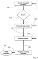
- the coupling process is now described with reference to the schematic flowchart of figure 3 as well as the schematic pneumatic diagram of figure 4 .
- the first coach 4 and the second coach 5 are in their normal, uncoupled condition 100.
- a coupling instruction 110 is generated.
- the coupling instruction 110 is generated by a switch detecting that the first and the second automatic couplers 13, 15 are in contact with each other.
- This coupling instruction 110 is received by the train control management system 25.
- the train control management system 25 upon receipt of the coupling instruction 110 generates a supply line coupling signal and sends the supply line coupling signal to the first automated coupler.
- the first automated coupler Upon receipt of the supply line coupling signal, the first automated coupler provides a coupling of electrical and pneumatical supply lines between the first coach 4 and the second coach 5. Successful coupling of the electrical and pneumatical supply lines is confirmed by a supply line confirmation signal 120
- the train control management system 25 Upon receipt of the supply line confirmation signal 120 the train control management system 25 generates a coupling signal 130 and sends the coupling signal to the first coupling actuator.
- the first coupling actuator drives the first locking mechanism from an unlocked state to a locked state. In the unlocked state of the first locking mechanism the first automatic coupler 13 is free to come into engagement with the second automatic coupler 15 or to disengage from the second automatic coupler 15. In the locked state the first automatic coupler 13 is mechanically coupled to the second automatic coupler 15 by a positive fit.
- the second coupling actuator is activated in the same way.
- the first and the second automatic couplers 13, 15 have a first and a second coupling sensor, respectively.
- the two coupling sensors are operatively coupled to the train control management system 25.
- the first and second coupling sensors generate first and second coupled signals 140 once the first and second locking mechanisms are in the locked state.
- the first and second coupled signals 140 are electrical signals received by the train control management system 25.
- the train control management system 25 sends an electrical first extend signal 150 to a first solenoid valve 26. Simultaneously, the train control management system 25 sends an electrical second extent signal to a second solenoid valve (not shown in the figures).
- Each of the first and second solenoid valves forms part of the controller. Control of the first and second bellows 12, 14 provided by the train control management system 25 in cooperation with the first solenoid valve 26 and the second solenoid valve. In the following operation of the first solenoid valve 26 to control automatic operation of the first bellows is described. Identical functionality is provided by the second solenoid valve for the second bellows 14.
- the set of first actuators 21, 23 of the first bellows is pneumatically operated using an outlet 27 of the train's pneumatic system (MRP).
- MRP train's pneumatic system
- the pressure of the pneumatic system is reduced by a pressure reducer 28.
- the pneumatic line branched from the train's pneumatic system with reduced pressure forms the input of the first solenoid valve 26.
- the first solenoid valve 26 forms an actively controlled manifold to activate the first motion cylinder 23 and the first latch cylinder 2.
- the first solenoid valve 26 Upon receipt of the first extend signal 150 the first solenoid valve 26 activates a pneumatic output of the first solenoid valve 26 powering the first motion cylinder 23.
- the first motion cylinder 23 drives the first coupling frame 16 from its retracted position into an extended position.
- the first and second coupling frames are distanced from their respective mounting frames until they meet in the middle between the first coach 4 and the second coach 5. In this position of the first and second coupling frames 16, the coupling frames can be latched to each other.
- a front face switch 24 In order to detect whether the first and second coupling frames 16 are in their correct extended positions for latching each of the first and second coupling frames 16 comprises a front face switch 24.
- the first front face switch 24 generates an electrical signal denoted as the first extended position signal 160.
- the first solenoid valve 26 as part of the controller receives the first extended position signal 160 the first solenoid valve 26 closes the pneumatic output towards the first motion cylinder 23 and opens the valve's output towards the first latch cylinder 21. Pressure on the valve's output connected to the first latch cylinder 21 is denoted the first latching signal 170.
- the first latching cylinder 21 drives the first latching mechanism 19 from an unlatched state into a latched state.
- the first coupling frame 16 is positively fitted to the second coupling frame.
- the first latch switch 22 sends an electrical first latched signal 180 to the train control management system 25.
- the first latched signal 180 confirms that in addition the coupling of the automatic couplers 13, 15 the mechanical coupling of the first and second bellows 12, 14 is completed.
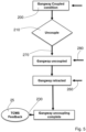
- Figures 5 and 6 describe the process of automatic uncoupling of the first and second coaches 4, 5. Again control of the process relies on the controller formed by the train control management system a first solenoid valve 26 and the second solenoid valve, respectively.
- the steps of the coupling process are activated in reverse order. In a first step the unlatching of the first and second bellows 12, 14 is carried out. In a second step the two bellows are retracted from their extended positions into their retracted positions. Finally, in a third step the automatic couplers 13, 15 are released.
Landscapes
- Engineering & Computer Science (AREA)
- Mechanical Engineering (AREA)
- Life Sciences & Earth Sciences (AREA)
- Wood Science & Technology (AREA)
- Lock And Its Accessories (AREA)
- Electric Propulsion And Braking For Vehicles (AREA)
Priority Applications (6)
| Application Number | Priority Date | Filing Date | Title |
|---|---|---|---|
| ES23154770T ES3033840T3 (en) | 2023-02-02 | 2023-02-02 | Automatic coupling |
| PL23154770.4T PL4410630T3 (pl) | 2023-02-02 | 2023-02-02 | Sprzęg automatyczny |
| EP23154770.4A EP4410630B1 (de) | 2023-02-02 | 2023-02-02 | Automatische kupplung |
| CA3208901A CA3208901A1 (en) | 2023-02-02 | 2023-08-10 | AUTOMATIC CONNECTION |
| US18/450,055 US20240262397A1 (en) | 2023-02-02 | 2023-08-15 | Automatic coupling |
| CN202311174906.0A CN118419088A (zh) | 2023-02-02 | 2023-09-12 | 自动联接 |
Applications Claiming Priority (1)
| Application Number | Priority Date | Filing Date | Title |
|---|---|---|---|
| EP23154770.4A EP4410630B1 (de) | 2023-02-02 | 2023-02-02 | Automatische kupplung |
Publications (3)
| Publication Number | Publication Date |
|---|---|
| EP4410630A1 true EP4410630A1 (de) | 2024-08-07 |
| EP4410630C0 EP4410630C0 (de) | 2025-05-14 |
| EP4410630B1 EP4410630B1 (de) | 2025-05-14 |
Family
ID=85173004
Family Applications (1)
| Application Number | Title | Priority Date | Filing Date |
|---|---|---|---|
| EP23154770.4A Active EP4410630B1 (de) | 2023-02-02 | 2023-02-02 | Automatische kupplung |
Country Status (6)
| Country | Link |
|---|---|
| US (1) | US20240262397A1 (de) |
| EP (1) | EP4410630B1 (de) |
| CN (1) | CN118419088A (de) |
| CA (1) | CA3208901A1 (de) |
| ES (1) | ES3033840T3 (de) |
| PL (1) | PL4410630T3 (de) |
Families Citing this family (1)
| Publication number | Priority date | Publication date | Assignee | Title |
|---|---|---|---|---|
| CN118833260B (zh) * | 2024-08-28 | 2025-10-31 | 中车青岛四方机车车辆股份有限公司 | 折棚连挂解编装置、贯通道组件及轨道车辆 |
Citations (4)
| Publication number | Priority date | Publication date | Assignee | Title |
|---|---|---|---|---|
| US2931317A (en) * | 1957-04-05 | 1960-04-05 | Pullman Standard Car Mfg Co | Railway car diaphragm alignment and roll-control apparatus |
| US4765249A (en) * | 1985-06-19 | 1988-08-23 | Narita Seisakusho Mfg., Ltd. | Gangway construction for vehicles |
| JP2944453B2 (ja) * | 1995-03-23 | 1999-09-06 | 九州旅客鉄道株式会社 | 車両用幌の自動連結方法 |
| CN113928063A (zh) * | 2021-11-12 | 2022-01-14 | 张钰 | 一种电客车的车辆贯通道结构 |
Family Cites Families (12)
| Publication number | Priority date | Publication date | Assignee | Title |
|---|---|---|---|---|
| US2746615A (en) * | 1954-09-02 | 1956-05-22 | Union Carbide & Carbon Corp | Remotely controlled car uncoupling systems |
| US3583574A (en) * | 1969-02-27 | 1971-06-08 | Ohio Brass Co | Remote uncoupling mechanism |
| US4049128A (en) * | 1976-11-18 | 1977-09-20 | Westinghouse Air Brake Company | Control system for automatic railway car coupler |
| US5152410A (en) * | 1991-09-09 | 1992-10-06 | Westinghouse Air Brake Company | Electro-pneumatic coupler control system for ensuring the safe uncoupling of railway vehicles |
| US6009813A (en) * | 1996-07-01 | 2000-01-04 | Hubner Gummi - Und Kunststoff | Connection between two vehicles hinged to one another, e.g. railway coaches or underground coaches |
| FR2901233B1 (fr) * | 2006-05-17 | 2009-02-27 | Eurolum Soc Par Actions Simpli | Vehicule sur roue, procede d'attelage, procede de desattelage, procede de gestion de ces vehicules et train de vehicules resultant |
| DE102018130813A1 (de) * | 2018-12-04 | 2020-06-04 | Bombardier Transportation Gmbh | Fahrzeugsegment für ein mehrgliedriges schienenfahrzeug und schienenfahrzeug |
| IT202000003671A1 (it) * | 2020-02-21 | 2021-08-21 | P E I Protezioni Elaborazioni Ind S R L | Dispositivo di fissaggio, gruppo di isolamento e procedimento corrispondenti. |
| EP3992051B1 (de) * | 2020-10-29 | 2023-08-30 | Dellner Couplers AB | Riffelblech für einen fussboden einer gangway sowie gangway |
| DE102021205166A1 (de) * | 2021-05-20 | 2022-11-24 | HÜBNER GmbH & Co. KG | Übergangssystem mit Schallabsorber |
| DE102021205651A1 (de) * | 2021-06-02 | 2021-09-16 | HÜBNER GmbH & Co. KG | Übergang zwischen zwei Fahrzeugteilen mit einer elektrischen Verbindungseinrichtung |
| CN114537456B (zh) * | 2022-04-06 | 2024-11-15 | 张建华 | 一种整体式高速列车内风挡 |
-
2023
- 2023-02-02 PL PL23154770.4T patent/PL4410630T3/pl unknown
- 2023-02-02 ES ES23154770T patent/ES3033840T3/es active Active
- 2023-02-02 EP EP23154770.4A patent/EP4410630B1/de active Active
- 2023-08-10 CA CA3208901A patent/CA3208901A1/en active Pending
- 2023-08-15 US US18/450,055 patent/US20240262397A1/en active Pending
- 2023-09-12 CN CN202311174906.0A patent/CN118419088A/zh active Pending
Patent Citations (4)
| Publication number | Priority date | Publication date | Assignee | Title |
|---|---|---|---|---|
| US2931317A (en) * | 1957-04-05 | 1960-04-05 | Pullman Standard Car Mfg Co | Railway car diaphragm alignment and roll-control apparatus |
| US4765249A (en) * | 1985-06-19 | 1988-08-23 | Narita Seisakusho Mfg., Ltd. | Gangway construction for vehicles |
| JP2944453B2 (ja) * | 1995-03-23 | 1999-09-06 | 九州旅客鉄道株式会社 | 車両用幌の自動連結方法 |
| CN113928063A (zh) * | 2021-11-12 | 2022-01-14 | 张钰 | 一种电客车的车辆贯通道结构 |
Also Published As
| Publication number | Publication date |
|---|---|
| ES3033840T3 (en) | 2025-08-08 |
| EP4410630C0 (de) | 2025-05-14 |
| EP4410630B1 (de) | 2025-05-14 |
| CN118419088A (zh) | 2024-08-02 |
| PL4410630T3 (pl) | 2025-07-07 |
| US20240262397A1 (en) | 2024-08-08 |
| CA3208901A1 (en) | 2025-04-28 |
Similar Documents
| Publication | Publication Date | Title |
|---|---|---|
| CN101511656B (zh) | 有线分布式电源的接口系统 | |
| EP4410630B1 (de) | Automatische kupplung | |
| CN108349513A (zh) | 用于自动联接以及释放行驶在铁路网上的车辆的系统 | |
| CN105059310B (zh) | 一种实现头尾车任意重联的控制系统及控制方法 | |
| US6206215B1 (en) | Rail car coupler | |
| CN112092857B (zh) | 一种轨道车辆的车钩及其气动控制方法 | |
| CN111055876B (zh) | 一种智能化车钩 | |
| US3556314A (en) | Automatic coupling system for rain brake lines | |
| CN204915712U (zh) | 一种实现头尾车任意重联的控制系统 | |
| CN105658497A (zh) | 列车编组中的气动制动系统冗余 | |
| DE102024107260A1 (de) | Steuerungssystem zur Steuerung einer Absperreinrichtung einer Luftleitung, ein spurgebundenes Fahrzeug und ein Verfahren zum Betreiben des Steuerungssystems | |
| KR101601881B1 (ko) | 철도 차량용 연결기 | |
| CN116803817B (zh) | 一种伸缩式钩缓装置自动控制系统及方法 | |
| CN114987578B (zh) | 一种轨道交通列车自动控制系统 | |
| CN210626062U (zh) | 一种线路碰撞试验驱动车 | |
| CN110308001B (zh) | 一种线路碰撞试验驱动车智能驱动方法 | |
| WO2014006389A1 (en) | Railway carriage interconnection system | |
| CN117460657A (zh) | 包括用于防止机械耦合器耦合的阻挡机构的耦合器及操作耦合器的方法 | |
| CN212709415U (zh) | 一种轨道车辆的车钩和轨道车辆 | |
| JP2001233202A (ja) | 鉄道車両の運転台位置自動認識方法及び認識装置 | |
| ITTO980668A1 (it) | Sistema di controllo e comunicazione per convogli ferroviari. | |
| CN201128420Y (zh) | 动车组密接车钩 | |
| US20230365172A1 (en) | Device And Method For The Data Transmission Between Parts Of A Rail Vehicle As Well As Part Of A Rail Vehicle | |
| US1636139A (en) | Car, air, and electric coupling system | |
| US2664299A (en) | Trailer landing gear |
Legal Events
| Date | Code | Title | Description |
|---|---|---|---|
| PUAI | Public reference made under article 153(3) epc to a published international application that has entered the european phase |
Free format text: ORIGINAL CODE: 0009012 |
|
| STAA | Information on the status of an ep patent application or granted ep patent |
Free format text: STATUS: THE APPLICATION HAS BEEN PUBLISHED |
|
| STAA | Information on the status of an ep patent application or granted ep patent |
Free format text: STATUS: REQUEST FOR EXAMINATION WAS MADE |
|
| AK | Designated contracting states |
Kind code of ref document: A1 Designated state(s): AL AT BE BG CH CY CZ DE DK EE ES FI FR GB GR HR HU IE IS IT LI LT LU LV MC ME MK MT NL NO PL PT RO RS SE SI SK SM TR |
|
| 17P | Request for examination filed |
Effective date: 20240715 |
|
| RBV | Designated contracting states (corrected) |
Designated state(s): AL AT BE BG CH CY CZ DE DK EE ES FI FR GB GR HR HU IE IS IT LI LT LU LV MC ME MK MT NL NO PL PT RO RS SE SI SK SM TR |
|
| GRAP | Despatch of communication of intention to grant a patent |
Free format text: ORIGINAL CODE: EPIDOSNIGR1 |
|
| STAA | Information on the status of an ep patent application or granted ep patent |
Free format text: STATUS: GRANT OF PATENT IS INTENDED |
|
| INTG | Intention to grant announced |
Effective date: 20241210 |
|
| GRAS | Grant fee paid |
Free format text: ORIGINAL CODE: EPIDOSNIGR3 |
|
| GRAA | (expected) grant |
Free format text: ORIGINAL CODE: 0009210 |
|
| STAA | Information on the status of an ep patent application or granted ep patent |
Free format text: STATUS: THE PATENT HAS BEEN GRANTED |
|
| AK | Designated contracting states |
Kind code of ref document: B1 Designated state(s): AL AT BE BG CH CY CZ DE DK EE ES FI FR GB GR HR HU IE IS IT LI LT LU LV MC ME MK MT NL NO PL PT RO RS SE SI SK SM TR |
|
| REG | Reference to a national code |
Ref country code: GB Ref legal event code: FG4D |
|
| REG | Reference to a national code |
Ref country code: CH Ref legal event code: EP |
|
| REG | Reference to a national code |
Ref country code: IE Ref legal event code: FG4D |
|
| REG | Reference to a national code |
Ref country code: DE Ref legal event code: R096 Ref document number: 602023003406 Country of ref document: DE |
|
| U01 | Request for unitary effect filed |
Effective date: 20250610 |
|
| U07 | Unitary effect registered |
Designated state(s): AT BE BG DE DK EE FI FR IT LT LU LV MT NL PT RO SE SI Effective date: 20250617 |
|
| REG | Reference to a national code |
Ref country code: ES Ref legal event code: FG2A Ref document number: 3033840 Country of ref document: ES Kind code of ref document: T3 Effective date: 20250808 |
|
| PG25 | Lapsed in a contracting state [announced via postgrant information from national office to epo] |
Ref country code: GR Free format text: LAPSE BECAUSE OF FAILURE TO SUBMIT A TRANSLATION OF THE DESCRIPTION OR TO PAY THE FEE WITHIN THE PRESCRIBED TIME-LIMIT Effective date: 20250815 |
|
| PG25 | Lapsed in a contracting state [announced via postgrant information from national office to epo] |
Ref country code: HR Free format text: LAPSE BECAUSE OF FAILURE TO SUBMIT A TRANSLATION OF THE DESCRIPTION OR TO PAY THE FEE WITHIN THE PRESCRIBED TIME-LIMIT Effective date: 20250514 |
|
| PG25 | Lapsed in a contracting state [announced via postgrant information from national office to epo] |
Ref country code: RS Free format text: LAPSE BECAUSE OF FAILURE TO SUBMIT A TRANSLATION OF THE DESCRIPTION OR TO PAY THE FEE WITHIN THE PRESCRIBED TIME-LIMIT Effective date: 20250814 |
|
| PG25 | Lapsed in a contracting state [announced via postgrant information from national office to epo] |
Ref country code: IS Free format text: LAPSE BECAUSE OF FAILURE TO SUBMIT A TRANSLATION OF THE DESCRIPTION OR TO PAY THE FEE WITHIN THE PRESCRIBED TIME-LIMIT Effective date: 20250914 |
|
| PG25 | Lapsed in a contracting state [announced via postgrant information from national office to epo] |
Ref country code: SM Free format text: LAPSE BECAUSE OF FAILURE TO SUBMIT A TRANSLATION OF THE DESCRIPTION OR TO PAY THE FEE WITHIN THE PRESCRIBED TIME-LIMIT Effective date: 20250514 |
|
| PG25 | Lapsed in a contracting state [announced via postgrant information from national office to epo] |
Ref country code: SK Free format text: LAPSE BECAUSE OF FAILURE TO SUBMIT A TRANSLATION OF THE DESCRIPTION OR TO PAY THE FEE WITHIN THE PRESCRIBED TIME-LIMIT Effective date: 20250514 |
|
| REG | Reference to a national code |
Ref country code: CH Ref legal event code: U11 Free format text: ST27 STATUS EVENT CODE: U-0-0-U10-U11 (AS PROVIDED BY THE NATIONAL OFFICE) Effective date: 20260301 |
|
| PLBE | No opposition filed within time limit |
Free format text: ORIGINAL CODE: 0009261 |
|
| STAA | Information on the status of an ep patent application or granted ep patent |
Free format text: STATUS: NO OPPOSITION FILED WITHIN TIME LIMIT |
|
| REG | Reference to a national code |
Ref country code: CH Ref legal event code: L10 Free format text: ST27 STATUS EVENT CODE: U-0-0-L10-L00 (AS PROVIDED BY THE NATIONAL OFFICE) Effective date: 20260325 |
|
| U20 | Renewal fee for the european patent with unitary effect paid |
Year of fee payment: 4 Effective date: 20260224 |
|
| 26N | No opposition filed |
Effective date: 20260217 |