EP4411006A1 - Duplexedelstahlmaterial - Google Patents
Duplexedelstahlmaterial Download PDFInfo
- Publication number
- EP4411006A1 EP4411006A1 EP22876209.2A EP22876209A EP4411006A1 EP 4411006 A1 EP4411006 A1 EP 4411006A1 EP 22876209 A EP22876209 A EP 22876209A EP 4411006 A1 EP4411006 A1 EP 4411006A1
- Authority
- EP
- European Patent Office
- Prior art keywords
- steel material
- content
- duplex stainless
- less
- stainless steel
- Prior art date
- Legal status (The legal status is an assumption and is not a legal conclusion. Google has not performed a legal analysis and makes no representation as to the accuracy of the status listed.)
- Pending
Links
Images
Classifications
-
- C—CHEMISTRY; METALLURGY
- C21—METALLURGY OF IRON
- C21D—MODIFYING THE PHYSICAL STRUCTURE OF FERROUS METALS; GENERAL DEVICES FOR HEAT TREATMENT OF FERROUS OR NON-FERROUS METALS OR ALLOYS; MAKING METAL MALLEABLE, e.g. BY DECARBURISATION OR TEMPERING
- C21D9/00—Heat treatment, e.g. annealing, hardening, quenching or tempering, adapted for particular articles; Furnaces therefor
- C21D9/08—Heat treatment, e.g. annealing, hardening, quenching or tempering, adapted for particular articles; Furnaces therefor for tubular bodies or pipes
-
- C—CHEMISTRY; METALLURGY
- C22—METALLURGY; FERROUS OR NON-FERROUS ALLOYS; TREATMENT OF ALLOYS OR NON-FERROUS METALS
- C22C—ALLOYS
- C22C38/00—Ferrous alloys, e.g. steel alloys
- C22C38/18—Ferrous alloys, e.g. steel alloys containing chromium
- C22C38/40—Ferrous alloys, e.g. steel alloys containing chromium with nickel
- C22C38/58—Ferrous alloys, e.g. steel alloys containing chromium with nickel with more than 1.5% by weight of manganese
-
- C—CHEMISTRY; METALLURGY
- C21—METALLURGY OF IRON
- C21D—MODIFYING THE PHYSICAL STRUCTURE OF FERROUS METALS; GENERAL DEVICES FOR HEAT TREATMENT OF FERROUS OR NON-FERROUS METALS OR ALLOYS; MAKING METAL MALLEABLE, e.g. BY DECARBURISATION OR TEMPERING
- C21D1/00—General methods or devices for heat treatment, e.g. annealing, hardening, quenching or tempering
- C21D1/18—Hardening; Quenching with or without subsequent tempering
-
- C—CHEMISTRY; METALLURGY
- C21—METALLURGY OF IRON
- C21D—MODIFYING THE PHYSICAL STRUCTURE OF FERROUS METALS; GENERAL DEVICES FOR HEAT TREATMENT OF FERROUS OR NON-FERROUS METALS OR ALLOYS; MAKING METAL MALLEABLE, e.g. BY DECARBURISATION OR TEMPERING
- C21D1/00—General methods or devices for heat treatment, e.g. annealing, hardening, quenching or tempering
- C21D1/26—Methods of annealing
- C21D1/28—Normalising
-
- C—CHEMISTRY; METALLURGY
- C21—METALLURGY OF IRON
- C21D—MODIFYING THE PHYSICAL STRUCTURE OF FERROUS METALS; GENERAL DEVICES FOR HEAT TREATMENT OF FERROUS OR NON-FERROUS METALS OR ALLOYS; MAKING METAL MALLEABLE, e.g. BY DECARBURISATION OR TEMPERING
- C21D1/00—General methods or devices for heat treatment, e.g. annealing, hardening, quenching or tempering
- C21D1/56—General methods or devices for heat treatment, e.g. annealing, hardening, quenching or tempering characterised by the quenching agents
- C21D1/60—Aqueous agents
-
- C—CHEMISTRY; METALLURGY
- C21—METALLURGY OF IRON
- C21D—MODIFYING THE PHYSICAL STRUCTURE OF FERROUS METALS; GENERAL DEVICES FOR HEAT TREATMENT OF FERROUS OR NON-FERROUS METALS OR ALLOYS; MAKING METAL MALLEABLE, e.g. BY DECARBURISATION OR TEMPERING
- C21D6/00—Heat treatment of ferrous alloys
- C21D6/004—Heat treatment of ferrous alloys containing Cr and Ni
-
- C—CHEMISTRY; METALLURGY
- C21—METALLURGY OF IRON
- C21D—MODIFYING THE PHYSICAL STRUCTURE OF FERROUS METALS; GENERAL DEVICES FOR HEAT TREATMENT OF FERROUS OR NON-FERROUS METALS OR ALLOYS; MAKING METAL MALLEABLE, e.g. BY DECARBURISATION OR TEMPERING
- C21D6/00—Heat treatment of ferrous alloys
- C21D6/005—Heat treatment of ferrous alloys containing Mn
-
- C—CHEMISTRY; METALLURGY
- C21—METALLURGY OF IRON
- C21D—MODIFYING THE PHYSICAL STRUCTURE OF FERROUS METALS; GENERAL DEVICES FOR HEAT TREATMENT OF FERROUS OR NON-FERROUS METALS OR ALLOYS; MAKING METAL MALLEABLE, e.g. BY DECARBURISATION OR TEMPERING
- C21D6/00—Heat treatment of ferrous alloys
- C21D6/02—Hardening by precipitation
-
- C—CHEMISTRY; METALLURGY
- C21—METALLURGY OF IRON
- C21D—MODIFYING THE PHYSICAL STRUCTURE OF FERROUS METALS; GENERAL DEVICES FOR HEAT TREATMENT OF FERROUS OR NON-FERROUS METALS OR ALLOYS; MAKING METAL MALLEABLE, e.g. BY DECARBURISATION OR TEMPERING
- C21D7/00—Modifying the physical properties of iron or steel by deformation
- C21D7/13—Modifying the physical properties of iron or steel by deformation by hot working
-
- C—CHEMISTRY; METALLURGY
- C21—METALLURGY OF IRON
- C21D—MODIFYING THE PHYSICAL STRUCTURE OF FERROUS METALS; GENERAL DEVICES FOR HEAT TREATMENT OF FERROUS OR NON-FERROUS METALS OR ALLOYS; MAKING METAL MALLEABLE, e.g. BY DECARBURISATION OR TEMPERING
- C21D8/00—Modifying the physical properties of ferrous metals or ferrous alloys by deformation combined with, or followed by, heat treatment
- C21D8/02—Modifying the physical properties of ferrous metals or ferrous alloys by deformation combined with, or followed by, heat treatment during manufacturing of plates or strips
- C21D8/0221—Modifying the physical properties of ferrous metals or ferrous alloys by deformation combined with, or followed by, heat treatment during manufacturing of plates or strips characterised by the working steps
- C21D8/0226—Hot rolling
-
- C—CHEMISTRY; METALLURGY
- C21—METALLURGY OF IRON
- C21D—MODIFYING THE PHYSICAL STRUCTURE OF FERROUS METALS; GENERAL DEVICES FOR HEAT TREATMENT OF FERROUS OR NON-FERROUS METALS OR ALLOYS; MAKING METAL MALLEABLE, e.g. BY DECARBURISATION OR TEMPERING
- C21D8/00—Modifying the physical properties of ferrous metals or ferrous alloys by deformation combined with, or followed by, heat treatment
- C21D8/02—Modifying the physical properties of ferrous metals or ferrous alloys by deformation combined with, or followed by, heat treatment during manufacturing of plates or strips
- C21D8/0247—Modifying the physical properties of ferrous metals or ferrous alloys by deformation combined with, or followed by, heat treatment during manufacturing of plates or strips characterised by the heat treatment
-
- C—CHEMISTRY; METALLURGY
- C21—METALLURGY OF IRON
- C21D—MODIFYING THE PHYSICAL STRUCTURE OF FERROUS METALS; GENERAL DEVICES FOR HEAT TREATMENT OF FERROUS OR NON-FERROUS METALS OR ALLOYS; MAKING METAL MALLEABLE, e.g. BY DECARBURISATION OR TEMPERING
- C21D8/00—Modifying the physical properties of ferrous metals or ferrous alloys by deformation combined with, or followed by, heat treatment
- C21D8/02—Modifying the physical properties of ferrous metals or ferrous alloys by deformation combined with, or followed by, heat treatment during manufacturing of plates or strips
- C21D8/0247—Modifying the physical properties of ferrous metals or ferrous alloys by deformation combined with, or followed by, heat treatment during manufacturing of plates or strips characterised by the heat treatment
- C21D8/0263—Modifying the physical properties of ferrous metals or ferrous alloys by deformation combined with, or followed by, heat treatment during manufacturing of plates or strips characterised by the heat treatment following hot rolling
-
- C—CHEMISTRY; METALLURGY
- C21—METALLURGY OF IRON
- C21D—MODIFYING THE PHYSICAL STRUCTURE OF FERROUS METALS; GENERAL DEVICES FOR HEAT TREATMENT OF FERROUS OR NON-FERROUS METALS OR ALLOYS; MAKING METAL MALLEABLE, e.g. BY DECARBURISATION OR TEMPERING
- C21D8/00—Modifying the physical properties of ferrous metals or ferrous alloys by deformation combined with, or followed by, heat treatment
- C21D8/06—Modifying the physical properties of ferrous metals or ferrous alloys by deformation combined with, or followed by, heat treatment during manufacturing of rods or wires
-
- C—CHEMISTRY; METALLURGY
- C21—METALLURGY OF IRON
- C21D—MODIFYING THE PHYSICAL STRUCTURE OF FERROUS METALS; GENERAL DEVICES FOR HEAT TREATMENT OF FERROUS OR NON-FERROUS METALS OR ALLOYS; MAKING METAL MALLEABLE, e.g. BY DECARBURISATION OR TEMPERING
- C21D8/00—Modifying the physical properties of ferrous metals or ferrous alloys by deformation combined with, or followed by, heat treatment
- C21D8/10—Modifying the physical properties of ferrous metals or ferrous alloys by deformation combined with, or followed by, heat treatment during manufacturing of tubular bodies
-
- C—CHEMISTRY; METALLURGY
- C21—METALLURGY OF IRON
- C21D—MODIFYING THE PHYSICAL STRUCTURE OF FERROUS METALS; GENERAL DEVICES FOR HEAT TREATMENT OF FERROUS OR NON-FERROUS METALS OR ALLOYS; MAKING METAL MALLEABLE, e.g. BY DECARBURISATION OR TEMPERING
- C21D9/00—Heat treatment, e.g. annealing, hardening, quenching or tempering, adapted for particular articles; Furnaces therefor
- C21D9/0075—Heat treatment, e.g. annealing, hardening, quenching or tempering, adapted for particular articles; Furnaces therefor for rods of limited length
-
- C—CHEMISTRY; METALLURGY
- C21—METALLURGY OF IRON
- C21D—MODIFYING THE PHYSICAL STRUCTURE OF FERROUS METALS; GENERAL DEVICES FOR HEAT TREATMENT OF FERROUS OR NON-FERROUS METALS OR ALLOYS; MAKING METAL MALLEABLE, e.g. BY DECARBURISATION OR TEMPERING
- C21D9/00—Heat treatment, e.g. annealing, hardening, quenching or tempering, adapted for particular articles; Furnaces therefor
- C21D9/08—Heat treatment, e.g. annealing, hardening, quenching or tempering, adapted for particular articles; Furnaces therefor for tubular bodies or pipes
- C21D9/085—Cooling or quenching
-
- C—CHEMISTRY; METALLURGY
- C21—METALLURGY OF IRON
- C21D—MODIFYING THE PHYSICAL STRUCTURE OF FERROUS METALS; GENERAL DEVICES FOR HEAT TREATMENT OF FERROUS OR NON-FERROUS METALS OR ALLOYS; MAKING METAL MALLEABLE, e.g. BY DECARBURISATION OR TEMPERING
- C21D9/00—Heat treatment, e.g. annealing, hardening, quenching or tempering, adapted for particular articles; Furnaces therefor
- C21D9/46—Heat treatment, e.g. annealing, hardening, quenching or tempering, adapted for particular articles; Furnaces therefor for sheet metals
-
- C—CHEMISTRY; METALLURGY
- C22—METALLURGY; FERROUS OR NON-FERROUS ALLOYS; TREATMENT OF ALLOYS OR NON-FERROUS METALS
- C22C—ALLOYS
- C22C38/00—Ferrous alloys, e.g. steel alloys
- C22C38/001—Ferrous alloys, e.g. steel alloys containing N
-
- C—CHEMISTRY; METALLURGY
- C22—METALLURGY; FERROUS OR NON-FERROUS ALLOYS; TREATMENT OF ALLOYS OR NON-FERROUS METALS
- C22C—ALLOYS
- C22C38/00—Ferrous alloys, e.g. steel alloys
- C22C38/002—Ferrous alloys, e.g. steel alloys containing In, Mg, or other elements not provided for in one single group C22C38/001 - C22C38/60
-
- C—CHEMISTRY; METALLURGY
- C22—METALLURGY; FERROUS OR NON-FERROUS ALLOYS; TREATMENT OF ALLOYS OR NON-FERROUS METALS
- C22C—ALLOYS
- C22C38/00—Ferrous alloys, e.g. steel alloys
- C22C38/004—Very low carbon steels, i.e. having a carbon content of less than 0,01%
-
- C—CHEMISTRY; METALLURGY
- C22—METALLURGY; FERROUS OR NON-FERROUS ALLOYS; TREATMENT OF ALLOYS OR NON-FERROUS METALS
- C22C—ALLOYS
- C22C38/00—Ferrous alloys, e.g. steel alloys
- C22C38/005—Ferrous alloys, e.g. steel alloys containing rare earths, i.e. Sc, Y, Lanthanides
-
- C—CHEMISTRY; METALLURGY
- C22—METALLURGY; FERROUS OR NON-FERROUS ALLOYS; TREATMENT OF ALLOYS OR NON-FERROUS METALS
- C22C—ALLOYS
- C22C38/00—Ferrous alloys, e.g. steel alloys
- C22C38/008—Ferrous alloys, e.g. steel alloys containing tin
-
- C—CHEMISTRY; METALLURGY
- C22—METALLURGY; FERROUS OR NON-FERROUS ALLOYS; TREATMENT OF ALLOYS OR NON-FERROUS METALS
- C22C—ALLOYS
- C22C38/00—Ferrous alloys, e.g. steel alloys
- C22C38/02—Ferrous alloys, e.g. steel alloys containing silicon
-
- C—CHEMISTRY; METALLURGY
- C22—METALLURGY; FERROUS OR NON-FERROUS ALLOYS; TREATMENT OF ALLOYS OR NON-FERROUS METALS
- C22C—ALLOYS
- C22C38/00—Ferrous alloys, e.g. steel alloys
- C22C38/04—Ferrous alloys, e.g. steel alloys containing manganese
-
- C—CHEMISTRY; METALLURGY
- C22—METALLURGY; FERROUS OR NON-FERROUS ALLOYS; TREATMENT OF ALLOYS OR NON-FERROUS METALS
- C22C—ALLOYS
- C22C38/00—Ferrous alloys, e.g. steel alloys
- C22C38/06—Ferrous alloys, e.g. steel alloys containing aluminium
-
- C—CHEMISTRY; METALLURGY
- C22—METALLURGY; FERROUS OR NON-FERROUS ALLOYS; TREATMENT OF ALLOYS OR NON-FERROUS METALS
- C22C—ALLOYS
- C22C38/00—Ferrous alloys, e.g. steel alloys
- C22C38/18—Ferrous alloys, e.g. steel alloys containing chromium
- C22C38/40—Ferrous alloys, e.g. steel alloys containing chromium with nickel
- C22C38/42—Ferrous alloys, e.g. steel alloys containing chromium with nickel with copper
-
- C—CHEMISTRY; METALLURGY
- C22—METALLURGY; FERROUS OR NON-FERROUS ALLOYS; TREATMENT OF ALLOYS OR NON-FERROUS METALS
- C22C—ALLOYS
- C22C38/00—Ferrous alloys, e.g. steel alloys
- C22C38/18—Ferrous alloys, e.g. steel alloys containing chromium
- C22C38/40—Ferrous alloys, e.g. steel alloys containing chromium with nickel
- C22C38/44—Ferrous alloys, e.g. steel alloys containing chromium with nickel with molybdenum or tungsten
-
- C—CHEMISTRY; METALLURGY
- C22—METALLURGY; FERROUS OR NON-FERROUS ALLOYS; TREATMENT OF ALLOYS OR NON-FERROUS METALS
- C22C—ALLOYS
- C22C38/00—Ferrous alloys, e.g. steel alloys
- C22C38/18—Ferrous alloys, e.g. steel alloys containing chromium
- C22C38/40—Ferrous alloys, e.g. steel alloys containing chromium with nickel
- C22C38/46—Ferrous alloys, e.g. steel alloys containing chromium with nickel with vanadium
-
- C—CHEMISTRY; METALLURGY
- C22—METALLURGY; FERROUS OR NON-FERROUS ALLOYS; TREATMENT OF ALLOYS OR NON-FERROUS METALS
- C22C—ALLOYS
- C22C38/00—Ferrous alloys, e.g. steel alloys
- C22C38/18—Ferrous alloys, e.g. steel alloys containing chromium
- C22C38/40—Ferrous alloys, e.g. steel alloys containing chromium with nickel
- C22C38/48—Ferrous alloys, e.g. steel alloys containing chromium with nickel with niobium or tantalum
-
- C—CHEMISTRY; METALLURGY
- C22—METALLURGY; FERROUS OR NON-FERROUS ALLOYS; TREATMENT OF ALLOYS OR NON-FERROUS METALS
- C22C—ALLOYS
- C22C38/00—Ferrous alloys, e.g. steel alloys
- C22C38/18—Ferrous alloys, e.g. steel alloys containing chromium
- C22C38/40—Ferrous alloys, e.g. steel alloys containing chromium with nickel
- C22C38/50—Ferrous alloys, e.g. steel alloys containing chromium with nickel with titanium or zirconium
-
- C—CHEMISTRY; METALLURGY
- C22—METALLURGY; FERROUS OR NON-FERROUS ALLOYS; TREATMENT OF ALLOYS OR NON-FERROUS METALS
- C22C—ALLOYS
- C22C38/00—Ferrous alloys, e.g. steel alloys
- C22C38/18—Ferrous alloys, e.g. steel alloys containing chromium
- C22C38/40—Ferrous alloys, e.g. steel alloys containing chromium with nickel
- C22C38/52—Ferrous alloys, e.g. steel alloys containing chromium with nickel with cobalt
-
- C—CHEMISTRY; METALLURGY
- C22—METALLURGY; FERROUS OR NON-FERROUS ALLOYS; TREATMENT OF ALLOYS OR NON-FERROUS METALS
- C22C—ALLOYS
- C22C38/00—Ferrous alloys, e.g. steel alloys
- C22C38/18—Ferrous alloys, e.g. steel alloys containing chromium
- C22C38/40—Ferrous alloys, e.g. steel alloys containing chromium with nickel
- C22C38/54—Ferrous alloys, e.g. steel alloys containing chromium with nickel with boron
-
- C—CHEMISTRY; METALLURGY
- C22—METALLURGY; FERROUS OR NON-FERROUS ALLOYS; TREATMENT OF ALLOYS OR NON-FERROUS METALS
- C22C—ALLOYS
- C22C38/00—Ferrous alloys, e.g. steel alloys
- C22C38/60—Ferrous alloys, e.g. steel alloys containing lead, selenium, tellurium, or antimony, or more than 0.04% by weight of sulfur
-
- C—CHEMISTRY; METALLURGY
- C21—METALLURGY OF IRON
- C21D—MODIFYING THE PHYSICAL STRUCTURE OF FERROUS METALS; GENERAL DEVICES FOR HEAT TREATMENT OF FERROUS OR NON-FERROUS METALS OR ALLOYS; MAKING METAL MALLEABLE, e.g. BY DECARBURISATION OR TEMPERING
- C21D1/00—General methods or devices for heat treatment, e.g. annealing, hardening, quenching or tempering
- C21D1/56—General methods or devices for heat treatment, e.g. annealing, hardening, quenching or tempering characterised by the quenching agents
- C21D1/613—Gases; Liquefied or solidified normally gaseous material
-
- C—CHEMISTRY; METALLURGY
- C21—METALLURGY OF IRON
- C21D—MODIFYING THE PHYSICAL STRUCTURE OF FERROUS METALS; GENERAL DEVICES FOR HEAT TREATMENT OF FERROUS OR NON-FERROUS METALS OR ALLOYS; MAKING METAL MALLEABLE, e.g. BY DECARBURISATION OR TEMPERING
- C21D2211/00—Microstructure comprising significant phases
- C21D2211/001—Austenite
-
- C—CHEMISTRY; METALLURGY
- C21—METALLURGY OF IRON
- C21D—MODIFYING THE PHYSICAL STRUCTURE OF FERROUS METALS; GENERAL DEVICES FOR HEAT TREATMENT OF FERROUS OR NON-FERROUS METALS OR ALLOYS; MAKING METAL MALLEABLE, e.g. BY DECARBURISATION OR TEMPERING
- C21D2211/00—Microstructure comprising significant phases
- C21D2211/004—Dispersions; Precipitations
-
- C—CHEMISTRY; METALLURGY
- C21—METALLURGY OF IRON
- C21D—MODIFYING THE PHYSICAL STRUCTURE OF FERROUS METALS; GENERAL DEVICES FOR HEAT TREATMENT OF FERROUS OR NON-FERROUS METALS OR ALLOYS; MAKING METAL MALLEABLE, e.g. BY DECARBURISATION OR TEMPERING
- C21D2211/00—Microstructure comprising significant phases
- C21D2211/005—Ferrite
Definitions
- the present disclosure relates to a duplex stainless steel material.
- Oil wells or gas wells may in some cases be a corrosive environment containing a corrosive gas.
- corrosive gas means carbon dioxide gas and/or hydrogen sulfide gas.
- steel materials for use in oil wells are required to have excellent corrosion resistance in a corrosive environment.
- a method in which the content of chromium (Cr) is increased to form a passive film mainly composed of Cr oxides on the surface of the steel material is already known as a method for improving the corrosion resistance of a steel material. Therefore, a duplex stainless steel material in which the content of Cr is made high may in some cases be used in an environment where excellent corrosion resistance is required. On the other hand, a duplex stainless steel material having a duplex microstructure consisting of a ferrite phase and an austenite phase is excellent in corrosion resistance with respect to pitting and/or crevice corrosion (hereinafter, referred to as "pitting resistance"), the corrosion being problematic in an aqueous solution containing chlorides.
- pitting resistance pitting resistance
- duplex stainless steel materials In recent years, furthermore, deep wells below sea level are being actively developed. Therefore, there is a need to enhance the strength of duplex stainless steel materials. That is, there is a growing demand for a duplex stainless steel material with which both a high strength and excellent pitting resistance are obtained.
- Patent Literature 1 Japanese Patent Application Publication No. 5-132741
- Patent Literature 2 Japanese Patent Application Publication No. 9-195003
- Patent Literature 3 Japanese Patent Application Publication No. 2014-043616
- Patent Literature 4 Japanese Patent Application Publication No. 2016-003377
- Patent Literature 4 each propose a duplex stainless steel that has a high strength and excellent corrosion resistance.
- Patent Literature 1 discloses that this duplex stainless steel exhibits excellent corrosion resistance and a high strength.
- the duplex stainless steel disclosed in Patent Literature 2 consists of, in weight%, C: 0.12% or less, Si: 1% or less, Mn: 2% or less, Ni: 3 to 12%, Cr: 20 to 35%, Mo: 0.5 to 10%, W: more than 3 to 8%, Co: 0.01 to 2%, Cu: 0.1 to 5%, and N: 0.05 to 0.5%, with the balance being Fe and unavoidable impurities.
- Patent Literature 2 discloses that this duplex stainless steel has further excellent corrosion resistance, without lowering the strength.
- Patent Literature 3 discloses that the strength of this duplex stainless steel can be enhanced without loss of corrosion resistance, and that by combining the use of cold working with a high reduction rate, this duplex stainless steel exhibits excellent hydrogen embrittlement resistance characteristics.
- the duplex stainless steel disclosed in Patent Literature 4 has a chemical composition consisting of, by mass%, C: 0.03% or less, Si: 0.2 to 1%, Mn: 0.5 to 2.0%, P: 0.040% or less, S: 0.010% or less, sol.
- Patent Literature 4 discloses that this duplex stainless steel is excellent in a strength, pitting resistance, and low-temperature toughness.
- the duplex stainless steel material is also required to have excellent low-temperature toughness in addition to a high strength and excellent pitting resistance when it is to be used for a deep well below sea level. Therefore, a duplex stainless steel material having a yield strength of 586 MPa or more, excellent low-temperature toughness, and excellent pitting resistance may be obtained by a technique other than the techniques disclosed in the aforementioned Patent Literatures 1 to 4.
- An objective of the present disclosure is to provide a duplex stainless steel material that has a yield strength of 586 MPa or more, excellent low-temperature toughness, and excellent pitting resistance.
- a duplex stainless steel material according to the present disclosure consists of, by mass%,
- the duplex stainless steel material according to the present disclosure has a high yield strength of 586 MPa or more, and has excellent low-temperature toughness and excellent pitting resistance.
- the present inventors conducted studies with respect to a duplex stainless steel material having a yield strength of 586 MPa or more, excellent low-temperature toughness, and excellent pitting resistance, from the viewpoint of the chemical composition.
- a duplex stainless steel material has a chemical composition consisting of, by mass%, C: 0.030% or less, Si: 0.20 to 1.00%, Mn: 0.50 to 7.00%, P: 0.040% or less, S: 0.020% or less, Al: 0.100% or less, Ni: 4.20 to 9.00%, Cr: 20.00 to 30.00%, Mo: 0.50 to 2.00%, Cu: 1.50 to 4.00%, N: 0.150 to 0.350%, V: 0.01 to 1.50%, Nb: 0 to 0.100%, Ta: 0 to 0.100%, Ti: 0 to 0.100%, Zr: 0 to 0.100%, Hf: 0 to 0.100%, W: 0 to 0.200%, Co: 0 to 0.500%,
- the microstructure of a duplex stainless steel material having the chemical composition described above consists of ferrite and austenite.
- the microstructure of the duplex stainless steel material having the chemical composition described above consists of, in volume ratio, ferrite in an amount of 30.0 to 70.0% with the balance being austenite.
- the phrase "consist of ferrite and austenite” means that an amount of any phase other than ferrite and austenite is negligibly small.
- the present inventors investigated various techniques for increasing the pitting resistance of the duplex stainless steel material that has the chemical composition described above and has the microstructure consisting of, in volume ratio, ferrite in an amount of 30.0 to 70.0% with the balance being austenite.
- the chemical composition of the duplex stainless steel material also satisfies the following Formula (1), the pitting resistance of the duplex stainless steel material will be increased: Cr + 3.3 Mo + 0.5 W + 16 N ⁇ 30.0 where, a content in percent by mass of a corresponding element is substituted for each symbol of an element in Formula (1), and if a corresponding element is not contained, "0" is substituted for the symbol of the corresponding element.
- Fn1 is an index relating to the pitting resistance of the steel material. If Fn1 is made high, the pitting resistance of the duplex stainless steel material can be increased. That is, if Fn1 is too low, the pitting resistance of the duplex stainless steel material will decrease. Accordingly, in the duplex stainless steel material according to the present embodiment, the chemical composition described above is satisfied, and Fn1 is made 30.0 or more.
- the present inventors investigated various techniques for increasing the low-temperature toughness and yield strength while maintaining the pitting resistance with respect to the duplex stainless steel material that satisfies the chemical composition described above, and in which Fn1 is made 30.0 or more, and which has the microstructure consisting of, in volume ratio, ferrite in an amount of 30.0 to 70.0% with the balance being austenite.
- Fn1 is made 30.0 or more
- the microstructure consisting of, in volume ratio, ferrite in an amount of 30.0 to 70.0% with the balance being austenite.
- the present inventors conducted studies regarding a technique for increasing the yield strength that focused on the microstructure of the duplex stainless steel material which satisfies the chemical composition described above and in which Fn1 is 30.0 or more.
- the strength of austenite is liable to be low in comparison to ferrite. Therefore, in the duplex stainless steel material that has the aforementioned chemical composition and microstructure and in which Fn1 is 30.0 or more, there is a possibility that the yield strength of the steel material overall will tend to decrease due to the characteristics of austenite.
- the present inventors investigated techniques for selectively increasing the strength of austenite while maintaining the pitting resistance and the low-temperature toughness.
- precipitates in a steel material increase the yield strength of the steel material. That is, there is a possibility that by purposely increasing precipitates which conventionally have been reduced, the strength of austenite will be increased and the yield strength of the duplex stainless steel material will be increased.
- the present inventors considered that if precipitates which do not tend to decrease the low-temperature toughness and pitting resistance can be selectively precipitated in austenite, it may be possible to increase the yield strength and low-temperature toughness while maintaining the pitting resistance of the duplex stainless steel material.
- Cu precipitates as a Cu precipitate in a steel material, and increases the yield strength of the steel material.
- coarse Cu precipitates a large number of fine Cu precipitates having a major axis of 50 nm or less (hereunder, also referred to simply as "fine Cu precipitates") precipitate, there is a possibility that the yield strength will be increased to 586 MPa or more while maintaining the pitting resistance and low-temperature toughness of the steel material.
- the present inventors conducted detailed investigations and studies regarding a relation between fine Cu precipitates in austenite and the yield strength in the duplex stainless steel material which satisfies the chemical composition described above, in which Fn1 is made 30.0 or more, and which has the microstructure consisting of, in volume ratio, ferrite in an amount of 30.0 to 70.0% with the balance being austenite.
- Fn1 is made 30.0 or more
- Fn1 is made 30.0 or more
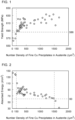
- FIG. 1 is a view illustrating the relation between the number density of fine Cu precipitates (/ ⁇ m 3 ) in austenite and the yield strength (MPa) of the steel material in the present Examples.
- FIG. 1 was created using the number densities of fine Cu precipitates (/ ⁇ m 3 ) in austenite and the yield strengths (MPa) with respect to, among Examples to be described later, duplex stainless steel materials satisfying the chemical composition described above and in which Fn1 was made 30.0 or more and which had the microstructure consisting of, in volume ratio, ferrite in an amount of 30.0 to 70.0% with the balance being austenite.
- Fn1 was made 30.0 or more and which had the microstructure consisting of, in volume ratio, ferrite in an amount of 30.0 to 70.0% with the balance being austenite.
- the number density of fine Cu precipitates and the yield strength were determined by methods that are described later. Further, each of the Examples illustrated in FIG. 1 exhibited excellent pitting resistance.
- the present inventors conducted detailed investigations and studies regarding the relation between fine Cu precipitates in austenite and the low-temperature toughness in the duplex stainless steel material satisfying the chemical composition described above in which Fn1 is made 30.0 or more and which has the microstructure consisting of, in volume ratio, ferrite in an amount of 30.0 to 70.0% with the balance being austenite. This is described specifically hereunder using the drawings.
- FIG. 2 is a view illustrating a relation between the number density of fine Cu precipitates (/ ⁇ m 3 ) in austenite and absorbed energy (J/cm 2 ) which is an index of the low-temperature toughness of the steel material in the present Examples.
- FIG. 2 was created using the number densities of fine Cu precipitates (/ ⁇ m 3 ) in austenite and the absorbed energy (J/cm 2 ) with respect to, among Examples to be described later, duplex stainless steel materials that satisfied the chemical composition described above, and in which Fn1 was made 30.0 or more and which had the microstructure consisting of, in volume ratio, ferrite in an amount of 30.0 to 70.0% with the balance being austenite. Note that, the number density of fine Cu precipitates and the absorbed energy were determined by methods that are described later. Further, each of the steel materials in FIG. 2 exhibited excellent pitting resistance.
- the duplex stainless steel material that satisfies the chemical composition described above and in which Fn1 is made 30.0 or more and which has the microstructure consisting of, in volume ratio, ferrite in an amount of 30.0 to 70.0% with the balance being austenite, if the number density of fine Cu precipitates in austenite is 150 to 1500 / ⁇ m 3 , the duplex stainless steel material has a high yield strength of 586 MPa or more and exhibits excellent low-temperature toughness while also maintaining excellent pitting resistance. Accordingly, in the present embodiment, the number density of fine Cu precipitates in austenite is made 150 to 1500 / ⁇ m 3 . As a result, the duplex stainless steel material according to the present embodiment has a high yield strength of 586 MPa or more, excellent low-temperature toughness, and excellent pitting resistance.
- the gist of the duplex stainless steel material according to the present embodiment which has been completed based on the above findings, is as follows.
- a shape of the duplex stainless steel material according to the present embodiment is not particularly limited.
- the duplex stainless steel material according to the present embodiment may be a steel pipe, may be a round steel bar (solid material), or may be a steel plate.
- round steel bar refers to a steel bar in which a cross section in a direction perpendicular to an axial direction is a circular shape.
- the steel pipe may be a seamless steel pipe or may be a welded steel pipe.
- duplex stainless steel material according to the present embodiment is described in detail. Note that, in the following description, the duplex stainless steel material is also referred to simply as a "steel material".
- the chemical composition of the duplex stainless steel material according to the present embodiment contains the following elements.
- the symbol "%" relating to an element means “mass percent” unless otherwise noted.
- Carbon (C) is unavoidably contained. That is, a lower limit of the content of C is more than 0%. C forms Cr carbides at grain boundaries and increases the corrosion susceptibility at the grain boundaries. Therefore, if the content of C is too high, the pitting resistance of the steel material will decrease even if the contents of other elements are within the range of the present embodiment. Therefore, the content of C is to be 0.030% or less. A preferable upper limit of the content of C is 0.028%, and more preferably is 0.025%. The content of C is preferably as low as possible. However, extremely reducing the content of C will significantly increase the production cost. Therefore, when industrial manufacturing is taken into consideration, a preferable lower limit of the content of C is 0.001%, and more preferably is 0.005%.
- Silicon (Si) deoxidizes the steel. If the content of Si is too low, the aforementioned advantageous effect will not be sufficiently obtained even if the contents of other elements are within the range of the present embodiment. On the other hand, if the content of Si is too high, the low-temperature toughness and hot workability of the steel material will decrease even if the contents of other elements are within the range of the present embodiment. Therefore, the content of Si is to be 0.20 to 1.00%. A preferable lower limit of the content of Si is 0.25%, and more preferably is 0.30%. A preferable upper limit of the content of Si is 0.80%, and more preferably is 0.60%.
- Manganese (Mn) deoxidizes the steel and desulfurizes the steel. Furthermore, Mn improves the hot workability of the steel material. If the content of Mn is too low, the aforementioned advantageous effects will not be sufficiently obtained even if the contents of other elements are within the range of the present embodiment. On the other hand, Mn segregates to grain boundaries together with impurities such as P and S. Therefore, if the content of Mn is too high, even if the contents of other elements are within the range of the present embodiment, the pitting resistance of the steel material in a high-temperature environment will decrease.
- the content of Mn is to be 0.50 to 7.00%.
- a preferable lower limit of the content of Mn is 0.75%, and more preferably is 1.00%.
- a preferable upper limit of the content of Mn is 6.50%, and more preferably is 6.20%.
- Phosphorus (P) is unavoidably contained. That is, the lower limit of the content of P is more than 0%. P segregates to grain boundaries. Therefore, if the content of P is too high, the low-temperature toughness and pitting resistance of the steel material will decrease even if the contents of other elements are within the range of the present embodiment. Therefore, the content of P is to be 0.040% or less. A preferable upper limit of the content of P is 0.035%, and more preferably is 0.030%. The content of P is preferably as low as possible. However, extremely reducing the content of P will significantly increase the production cost. Therefore, when industrial manufacturing is taken into consideration, a preferable lower limit of the content of P is 0.001%, and more preferably is 0.003%.
- S Sulfur
- the lower limit of the content of S is more than 0%. S segregates to grain boundaries. Therefore, if the content of S is too high, the low-temperature toughness and pitting resistance of the steel material will decrease even if the contents of other elements are within the range of the present embodiment. Therefore, the content of S is to be 0.020% or less.
- a preferable upper limit of the content of S is 0.018%, and more preferably is 0.016%.
- the content of S is preferably as low as possible. However, extremely reducing the content of S will significantly increase the production cost. Therefore, when industrial manufacturing is taken into consideration, a preferable lower limit of the content of S is 0.0001%, more preferably is 0.0003%, further preferably is 0.001%, and further preferably is 0.002%.
- Aluminum (Al) is unavoidably contained. That is, the lower limit of the content of Al is more than 0%. Al deoxidizes the steel. On the other hand, if the content of Al is too high, coarse oxide-based inclusions will form and the low-temperature toughness of the steel material will decrease even if the contents of other elements are within the range of the present embodiment. Therefore, the content of Al is to be 0.100% or less.
- a preferable lower limit of the content of Al is 0.001%, more preferably is 0.005%, and further preferably is 0.010%.
- a preferable upper limit of the content of Al is 0.090%, and more preferably is 0.085%. Note that, as used in the present description, the term "content of Al" means the content of "acid-soluble Al," that is, the content of sol. Al.
- Nickel (Ni) stabilizes the austenitic microstructure of the steel material. That is, Ni is an element necessary for obtaining a stable duplex microstructure consisting of ferrite and austenite. Ni also increases the pitting resistance of the steel material. If the content of Ni is too low, the aforementioned advantageous effects will not be sufficiently obtained even if the contents of other elements are within the range of the present embodiment. On the other hand, if the content of Ni is too high, even if the contents of other elements are within the range of the present embodiment, the volume ratio of austenite will be too high, and the yield strength of the steel material will decrease. Therefore, the content of Ni is to be 4.20 to 9.00%.
- a preferable lower limit of the content of Ni is 4.25%, more preferably is 4.30%, further preferably is 4.35%, further preferably is 4.40%, and further preferably is 4.50%.
- a preferable upper limit of the content of Ni is 8.75%, more preferably is 8.50%, further preferably is 8.25%, further preferably is 8.00%, and further preferably is 7.75%.
- Chromium (Cr) increases the pitting resistance of the steel material. Specifically, Cr forms a passive film as oxides on the surface of the steel material. As a result, the pitting resistance of the steel material increases. Cr also increases the volume ratio of the ferritic microstructure of the steel material. By obtaining a sufficient ferritic microstructure, the pitting resistance of the steel material is stabilized. If the content of Cr is too low, the aforementioned advantageous effects will not be sufficiently obtained even if the contents of other elements are within the range of the present embodiment. On the other hand, if the content of Cr is too high, the hot workability of the steel material will decrease even if the contents of other elements are within the range of the present embodiment. Therefore, the content of Cr is to be 20.00 to 30.00%.
- a preferable lower limit of the content of Cr is 20.50%, more preferably is 21.00%, and further preferably is 21.50%.
- a preferable upper limit of the content of Cr is 29.50%, more preferably is 29.00%, and further preferably is 28.00%.
- Molybdenum (Mo) increases the pitting resistance of the steel material. Mo also dissolves in the steel and increases the yield strength of the steel material. In addition, Mo forms fine carbides in the steel and increases the yield strength of the steel material. If the content of Mo is too low, the aforementioned advantageous effects will not be sufficiently obtained even if the contents of other elements are within the range of the present embodiment. On the other hand, if the content of Mo is too high, the hot workability of the steel material will decrease even if the contents of other elements are within the range of the present embodiment. Therefore, the content of Mo is to be 0.50 to 2.00%. A preferable lower limit of the content of Mo is 0.60%, more preferably is 0.70%, and further preferably is 0.80%. A preferable upper limit of the content of Mo is less than 2.00%, more preferably is 1.85%, and further preferably is 1.50%.
- a preferable lower limit of the content of Cu is 1.60%, more preferably is 1.80%, further preferably is 1.90%, further preferably is 2.00%, and further preferably is 2.50%.
- a preferable upper limit of the content of Cu is 3.90%, more preferably is 3.75%, and further preferably is 3.50%.
- N Nitrogen
- N stabilizes the austenitic microstructure of the steel material. That is, N is an element necessary for obtaining a stable duplex microstructure consisting of ferrite and austenite. N also increases the pitting resistance of the steel material. If the content of N is too low, the aforementioned advantageous effects will not be sufficiently obtained even if the contents of other elements are within the range of the present embodiment. On the other hand, if the content of N is too high, even if the contents of other elements are within the range of the present embodiment, the low-temperature toughness and hot workability of the steel material will decrease. Therefore, the content of N is to be 0.150 to 0.350%. A preferable lower limit of the content of N is 0.170%, more preferably is 0.180%, and further preferably is 0.190%. A preferable upper limit of the content of N is 0.340%, and more preferably is 0.330%.
- Vanadium (V) increases the yield strength of the steel material. If the content of V is too low, the aforementioned advantageous effect will not be sufficiently obtained even if the contents of other elements are within the range of the present embodiment. On the other hand, if the content of V is too high, even if the contents of other elements are within the range of the present embodiment, the strength of the steel material will be too high, and the low-temperature toughness and hot workability of the steel material will decrease. Therefore, the content of V is to be 0.01 to 1.50%. A preferable lower limit of the content of V is 0.02%, more preferably is 0.03%, and further preferably is 0.05%. A preferable upper limit of the content of V is 1.20%, and more preferably is 1.00%.
- the balance of the chemical composition of the duplex stainless steel material according to the present embodiment is Fe and impurities.
- impurities in the chemical composition refers to those elements and the like which are mixed in from ore and scrap as the raw material or from the production environment or the like when industrially producing the duplex stainless steel material, and which are permitted within a range that does not adversely affect the duplex stainless steel material according to the present embodiment.
- the chemical composition of the duplex stainless steel material described above may further contain one or more elements selected from a group consisting of Nb, Ta, Ti, Zr, Hf, and W in lieu of a part of Fe. Each of these elements is an optional element, and increases the strength of the steel material.
- Niobium (Nb) is an optional element, and does not have to be contained. That is, the content of Nb may be 0%. When contained, Nb forms carbo-nitrides and increases the strength of the steel material. If even a small amount of Nb is contained, the aforementioned advantageous effect will be obtained to a certain extent. However, if the content of Nb is too high, even if the contents of other elements are within the range of the present embodiment, the strength of the steel material will be too high and the low-temperature toughness of the steel material will decrease. Therefore, the content of Nb is to be 0 to 0.100%.
- a preferable lower limit of the content of Nb is more than 0%, more preferably is 0.001%, further preferably is 0.002%, further preferably is 0.003%, and further preferably is 0.005%.
- a preferable upper limit of the content of Nb is 0.080%, and more preferably is 0.070%.
- Tantalum (Ta) is an optional element, and does not have to be contained. That is, the content of Ta may be 0%. When contained, Ta forms carbo-nitrides and increases the strength of the steel material. If even a small amount of Ta is contained, the aforementioned advantageous effect will be obtained to a certain extent. However, if the content of Ta is too high, even if the contents of other elements are within the range of the present embodiment, the strength of the steel material will be too high and the low-temperature toughness of the steel material will decrease. Therefore, the content of Ta is to be 0 to 0.100%.
- a preferable lower limit of the content of Ta is more than 0%, more preferably is 0.001%, further preferably is 0.002%, further preferably is 0.003%, and further preferably is 0.005%.
- a preferable upper limit of the content of Ta is 0.080%, and more preferably is 0.070%.
- Titanium (Ti) is an optional element, and does not have to be contained. That is, the content of Ti may be 0%. When contained, Ti forms carbo-nitrides and increases the strength of the steel material. If even a small amount of Ti is contained, the aforementioned advantageous effect will be obtained to a certain extent. However, if the content of Ti is too high, even if the contents of other elements are within the range of the present embodiment, the strength of the steel material will be too high and the low-temperature toughness of the steel material will decrease. Therefore, the content of Ti is to be 0 to 0.100%.
- a preferable lower limit of the content of Ti is more than 0%, more preferably is 0.001%, further preferably is 0.002%, further preferably is 0.003%, and further preferably is 0.005%.
- a preferable upper limit of the content of Ti is 0.080%, and more preferably is 0.070%.
- Zirconium (Zr) is an optional element, and does not have to be contained. That is, the content of Zr may be 0%. When contained, Zr forms carbo-nitrides and increases the strength of the steel material. If even a small amount of Zr is contained, the aforementioned advantageous effect will be obtained to a certain extent. However, if the content of Zr is too high, even if the contents of other elements are within the range of the present embodiment, the strength of the steel material will be too high and the low-temperature toughness of the steel material will decrease. Therefore, the content of Zr is to be 0 to 0.100%.
- a preferable lower limit of the content of Zr is more than 0%, more preferably is 0.001%, further preferably is 0.002%, further preferably is 0.003%, and further preferably is 0.005%.
- a preferable upper limit of the content of Zr is 0.080%, and more preferably is 0.070%.
- Hafnium (Hf) is an optional element, and does not have to be contained. That is, the content of Hf may be 0%. When contained, Hf forms carbo-nitrides and increases the strength of the steel material. If even a small amount of Hf is contained, the aforementioned advantageous effect will be obtained to a certain extent. However, if the content of Hf is too high, even if the contents of other elements are within the range of the present embodiment, the strength of the steel material will be too high and the low-temperature toughness of the steel material will decrease. Therefore, the content of Hf is to be 0 to 0.100%.
- a preferable lower limit of the content of Hf is more than 0%, more preferably is 0.001%, further preferably is 0.002%, further preferably is 0.003%, and further preferably is 0.005%.
- a preferable upper limit of the content of Hf is 0.080%, and more preferably is 0.070%.
- Tungsten (W) is an optional element, and does not have to be contained. That is, the content of W may be 0%. When contained, W forms carbo-nitrides and increases the strength of the steel material. If even a small amount of W is contained, the aforementioned advantageous effect will be obtained to a certain extent. However, if the content of W is too high, even if the contents of other elements are within the range of the present embodiment, the strength of the steel material will be too high and the low-temperature toughness of the steel material will decrease. Therefore, the content of W is to be 0 to 0.200%.
- a preferable lower limit of the content of W is more than 0%, more preferably is 0.001%, further preferably is 0.002%, further preferably is 0.003%, and further preferably is 0.005%.
- a preferable upper limit of the content of W is 0.180%, and more preferably is 0.150%.
- the chemical composition of the duplex stainless steel material described above may further contain one or more elements selected from a group consisting of Co, Sn, and Sb in lieu of a part of Fe. Each of these elements is an optional element, and enhances the corrosion resistance of the steel material.
- Co Co is an optional element, and does not have to be contained. That is, the content of Co may be 0%. When contained, Co forms a coating on the surface of the steel material, and thereby enhances the corrosion resistance of the steel material. Co also increases the hardenability of the steel material and stabilizes the strength of the steel material. If even a small amount of Co is contained, the aforementioned advantageous effects will be obtained to a certain extent. However, if the content of Co is too high, the production cost will increase extremely, even if the contents of other elements are within the range of the present embodiment. Therefore, the content of Co is to be 0 to 0.500%.
- a preferable lower limit of the content of Co is more than 0%, more preferably is 0.001%, further preferably is 0.010%, and further preferably is 0.020%.
- a preferable upper limit of the content of Co is 0.480%, more preferably is 0.460%, and further preferably is 0.450%.
- Tin (Sn) is an optional element, and does not have to be contained. That is, the content of Sn may be 0%. When contained, Sn enhances the corrosion resistance of the steel material. If even a small amount of Sn is contained, the aforementioned advantageous effect will be obtained to a certain extent. However, if the content of Sn is too high, even if the contents of other elements are within the range of the present embodiment, liquation cracking will occur at grain boundaries and consequently the hot workability of the steel material will decrease. Therefore, the content of Sn is to be 0 to 0.100%. A preferable lower limit of the content of Sn is more than 0%, more preferably is 0.001%, further preferably is 0.002%, and further preferably is 0.003%. A preferable upper limit of the content of Sn is 0.080%, and more preferably is 0.070%.
- Antimony (Sb) is an optional element, and does not have to be contained. That is, the content of Sb may be 0%. When contained, Sb enhances the corrosion resistance of the steel material. If even a small amount of Sb is contained, the aforementioned advantageous effect will be obtained to a certain extent. However, if the content of Sb is too high, even if the contents of other elements are within the range of the present embodiment, the high-temperature ductility of the steel material will decrease, and the hot workability of the steel material will decrease. Therefore, the content of Sb is to be 0 to 0.100%. A preferable lower limit of the content of Sb is more than 0%, more preferably is 0.001%, further preferably is 0.002%, and further preferably is 0.003%. A preferable upper limit of the content of Sb is 0.080%, and more preferably is 0.070%.
- the chemical composition of the duplex stainless steel material described above may further contain one or more elements selected from a group consisting of Ca, Mg, B, and rare earth metal in lieu of a part of Fe. Each of these elements is an optional element, and increases the hot workability of the steel material.
- Ca Calcium (Ca) is an optional element, and does not have to be contained. That is, the content of Ca may be 0%. When contained, Ca fixes S in the steel material as a sulfide to make it harmless, and thereby increases the hot workability of the steel material. If even a small amount of Ca is contained, the aforementioned advantageous effect will be obtained to a certain extent. However, if the content of Ca is too high, even if the contents of other elements are within the range of the present embodiment, oxides in the steel material will coarsen and the low-temperature toughness of the steel material will decrease. Therefore, the content of Ca is to be 0 to 0.020%.
- a preferable lower limit of the content of Ca is more than 0%, more preferably is 0.001%, further preferably is 0.002%, further preferably is 0.003%, and further preferably is 0.005%.
- a preferable upper limit of the content of Ca is 0.018%, and more preferably is 0.015%.
- Magnesium (Mg) is an optional element, and does not have to be contained. That is, the content of Mg may be 0%. When contained, Mg fixes S in the steel material as a sulfide to make it harmless, and thereby increases the hot workability of the steel material. If even a small amount of Mg is contained, the aforementioned advantageous effect will be obtained to a certain extent. However, if the content of Mg is too high, even if the contents of other elements are within the range of the present embodiment, oxides in the steel material will coarsen and the low-temperature toughness of the steel material will decrease. Therefore, the content of Mg is to be 0 to 0.020%.
- a preferable lower limit of the content of Mg is more than 0%, more preferably is 0.001%, further preferably is 0.002%, further preferably is 0.003%, and further preferably is 0.005%.
- a preferable upper limit of the content of Mg is 0.018%, and more preferably is 0.015%.
- Boron (B) is an optional element, and does not have to be contained. That is, the content of B may be 0%. When contained, B suppresses segregation of S in the steel material to grain boundaries, and thereby increases the hot workability of the steel material. If even a small amount of B is contained, the aforementioned advantageous effect will be obtained to a certain extent. However, if the content of B is too high, even if the contents of other elements are within the range of the present embodiment, boron nitride (BN) will be formed and will cause the low-temperature toughness of the steel material to decrease. Therefore, the content of B is to be 0 to 0.020%.
- a preferable lower limit of the content of B is more than 0%, more preferably is 0.001%, further preferably is 0.002%, further preferably is 0.003%, and further preferably is 0.005%.
- a preferable upper limit of the content of B is 0.018%, and more preferably is 0.015%.
- Rare earth metal 0 to 0.200%
- Rare earth metal is an optional element, and does not have to be contained. That is, the content of REM may be 0%. When contained, REM fixes S in the steel material as a sulfide to make it harmless, and thereby increases the hot workability of the steel material. If even a small amount of REM is contained, the aforementioned advantageous effect will be obtained to a certain extent. However, if the content of REM is too high, even if the contents of other elements are within the range of the present embodiment, oxides in the steel material will coarsen and the low-temperature toughness of the steel material will decrease. Therefore, the content of REM is to be 0 to 0.200%.
- a preferable lower limit of the content of REM is more than 0%, more preferably is 0.001%, further preferably is 0.005%, further preferably is 0.010%, and further preferably is 0.020%.
- a preferable upper limit of the content of REM is 0.180%, and more preferably is 0.160%.
- REM means one or more elements selected from a group consisting of scandium (Sc) with atomic number 21, yttrium (Y) with atomic number 39, and the elements from lanthanum (La) with atomic number 57 to lutetium (Lu) with atomic number 71 that are lanthanoids.
- content of REM refers to the total content of these elements.
- the chemical composition of the duplex stainless steel material according to the present embodiment also satisfies the following Formula (1): Cr + 3.3 Mo + 0.5 W + 16 N ⁇ 30 .0 where, a content in percent by mass of a corresponding element is substituted for each symbol of an element in Formula (1), and if a corresponding element is not contained, "0" is substituted for the symbol of the corresponding element.
- a preferable lower limit of Fn1 is 30.5, more preferably is 31.0, and further preferably is 31.5. It is preferable for the value of Fn1 to be high. However, in the duplex stainless steel material according to the present embodiment which has the chemical composition described above, the upper limit of Fn1 is substantially 42.5. Note that, in the present embodiment, a value obtained by rounding off to the first decimal place of the obtained numerical value is adopted as Fn1.
- the microstructure of the duplex stainless steel material according to the present embodiment consists of, in volume ratio, ferrite in an amount of 30.0 to 70.0% with the balance being austenite.
- the phrase "consist of ferrite and austenite” means that the amount of any phase other than ferrite and austenite is negligibly small.
- volume ratios of precipitates and inclusions are negligibly low as compared with the volume ratio of ferrite and austenite. That is, the microstructure of the duplex stainless steel material according to the present embodiment may contain minute amounts of precipitates, inclusions and the like, in addition to ferrite and austenite.
- the volume ratio of ferrite is 30.0 to 70.0%. If the volume ratio of ferrite is too low, in some cases the yield strength and/or the pitting resistance of the steel material may decrease. On the other hand, if the volume ratio of ferrite is too high, in some cases the low-temperature toughness and/or hot workability of the steel material may decrease. Therefore, in the microstructure of the duplex stainless steel material according to the present embodiment, the volume ratio of ferrite is 30.0 to 70.0%. A preferable lower limit of the volume ratio of ferrite is 31.0%, and more preferably is 32.0%. A preferable upper limit of the volume ratio of ferrite is 68.0%, and more preferably is 65.0%.
- the volume ratio of ferrite in the duplex stainless steel material can be determined by a method in accordance with ASTM E562 (2019).
- a test specimen for microstructure observation is prepared from the duplex stainless steel material according to the present embodiment. If the steel material is a steel plate, a test specimen having an observation surface with dimensions of 5 mm in a rolling direction and 5 mm in a thickness direction is prepared from a center portion of a thickness. If the steel material is a steel pipe, a test specimen having an observation surface with dimensions of 5 mm in a pipe axis direction and 5 mm in a pipe diameter direction is prepared from a center portion of a wall thickness.
- the steel material is a round steel bar
- a test specimen having an observation surface with dimensions of 5 mm in an axial direction and 5 mm in a radial direction is prepared from an R/2 position.
- the R/2 position of a round steel bar means a center position of a radius R in a cross section perpendicular to the axial direction of the round steel bar.
- a size of the test specimen is not particularly limited as long as the aforementioned observation surface can be obtained.
- the observation surface of the prepared test specimen is mirror-polished.
- the mirror-polished observation surface is electrolytically etched in a 7% potassium hydroxide etching solution to reveal the microstructure.
- the observation surface on which the microstructure has been revealed is observed in 10 visual fields using an optical microscope.
- An area of each visual field is not particularly limited, and for example is 1.00 mm 2 (magnification of 100 ⁇ ).
- ferrite is identified based on contrast.
- An area fraction of the identified ferrite is measured by a point counting method in accordance with ASTM E562 (2019).
- an arithmetic average value of the area fractions of ferrite obtained in the 10 visual fields is defined as the volume ratio (%) of ferrite.
- a value obtained by rounding off to first decimal place of the obtained value is adopted as the volume ratio (%) of ferrite.
- the number density of Cu precipitates having a major axis of 50 nm or less in austenite is 150 to 1500 / ⁇ m 3 .
- Cu precipitates having a major axis of 50 nm or less are also referred to as "fine Cu precipitates”. Note that, in the present description, the term "Cu precipitates” means precipitates composed of Cu and impurities.
- Cu precipitates in elementary analysis performed by Energy Dispersive X-ray Spectrometry (hereunder, also referred to as an "EDS") to be described later, among the element concentrations for Fe, Cr, Ni, Cu, Mn, Mo, and Si, those precipitates in which a concentration of 15.0% by mass or more of Cu is detected are defined as "Cu precipitates”.
- EDS Energy Dispersive X-ray Spectrometry
- duplex stainless steel materials conventionally precipitates in the steel materials have been reduced for the purpose of increasing the pitting resistance of the steel materials.
- fine Cu precipitates in austenite increase the yield strength of a steel material.
- the influence of fine Cu precipitates on the low-temperature toughness and the pitting resistance of a steel material is small. Therefore, in the duplex stainless steel material according to the present embodiment, fine Cu precipitates that have little influence on low-temperature toughness and pitting resistance are purposely caused to precipitate in austenite.
- the yield strength of the steel material can be increased while maintaining the pitting resistance.
- the number density of fine Cu precipitates in austenite is made to fall within the range of 150 to 1500 / ⁇ m 3 .
- a high yield strength of 586 MPa or more can be obtained while maintaining excellent low-temperature toughness and excellent pitting resistance.
- a preferable lower limit of the number density of fine Cu precipitates in austenite in the duplex stainless steel material according to the present embodiment is 156 / ⁇ m 3 , and more preferably is 160 / ⁇ m 3 .
- a preferable upper limit of the number density of fine Cu precipitates in austenite in the duplex stainless steel material according to the present embodiment is 1200 / ⁇ m 3 , more preferably is 900 / ⁇ m 3 , and further preferably is 600 / ⁇ m 3 .
- the number density of fine Cu precipitates in austenite can be determined by the following method.
- a thin film test specimen for observation of fine Cu precipitates is prepared from the steel material according to the present embodiment. If the steel material is a steel plate, the thin film test specimen is prepared from a center portion of the thickness. If the steel material is a steel pipe, the thin film test specimen is prepared from a center portion of the wall thickness. If the steel material is a round steel bar, the thin film test specimen is prepared from an R/2 position. Note that, the thin film test specimen is prepared by electropolishing using a twin-jet method. Further, a size of the thin film test specimen is not particularly limited as long as an observation visual field to be described later can be obtained.
- an arbitrary four visual fields are specified from the austenite.
- the austenite in the observation surface can be identified by identification of a crystal structure by electron diffraction.
- the specified four visual fields are subjected to microstructure observation using a transmission electron microscope (hereinafter, also referred to as a "TEM").
- TEM transmission electron microscope
- the arbitrary four visual fields are specified as observation visual fields.
- an area of each observation visual field is set to, for example, 800 nm ⁇ 800 nm.
- precipitates are photographed by performing exposure for an appropriate time.
- precipitates are identified based on contrast.
- precipitates having a major axis of 50 nm or less are identified by performing a comparison with a scale bar in the images. Note that, identification of precipitates having a major axis of 50 nm or less in the observation visual fields can be, as a matter of course, performed by a person skilled in the art.
- the precipitates having a major axis of 50 nm or less in austenite as identified in the manner described above are subjected to elementary analysis by the EDS.
- element concentrations are determined for Fe, Cr, Ni, Cu, Mn, Mo, and Si as elements to be analyzed.
- elementary analysis is performed with respect to a range that has a certain volume. That is, even when precipitates are present at the observation surface, elementary analysis of only the precipitates cannot be performed, and the base metal is also simultaneously subjected to elementary analysis. Accordingly, when elementary analysis by the EDS is performed in a region in which Cu precipitates are present at the observation surface, elements (Fe and the like) derived from the base metal are also simultaneously detected in addition to Cu.
- the content of Cu in the base metal is, as mentioned above, 1.50 to 4.00%. Therefore, in elementary analysis by the EDS, if a precipitate has a Cu concentration of 15.0% by mass or more, it can be determined that the precipitate is a Cu precipitate. In each observation visual field, the number of precipitates which have a major axis of 50 nm or less and which have a Cu concentration of 15.0% by mass or more (fine Cu precipitates) is counted. In addition, the volume ( ⁇ m 3 ) of each observation region is determined based on the area of each observation visual field and the thickness of the observation region. Note that, the thickness of the observation region can be determined based on, with respect to the thin film test specimen, the total integrated intensity of an electron energy loss spectrum (EELS) and the integrated intensity of a zero-loss spectrum.
- EELS electron energy loss spectrum
- the number density of fine Cu precipitates (/ ⁇ m 3 ) in each observation visual field is determined based on the obtained number (pieces) of Cu precipitates having a major axis of 50 nm or less in each observation visual field and the volume ( ⁇ m 3 ) of each observation visual field.
- An arithmetic average value of the number densities of fine Cu precipitates obtained in the four visual fields is defined as the number density of fine Cu precipitates (/ ⁇ m 3 ) in austenite.
- a value obtained by rounding off to first decimal place of the obtained numerical value is adopted as the number density of fine Cu precipitates (/ ⁇ m 3 ) in austenite.
- the yield strength of the duplex stainless steel material according to the present embodiment is 586 MPa or more.
- the duplex stainless steel material according to the present embodiment has the chemical composition described above and also satisfies Formula (1), and has the microstructure consisting of, in volume ratio, ferrite in an amount of 30.0 to 70.0% with the balance being austenite, and furthermore, the number density of Cu precipitates having a major axis of 50 nm or less in austenite in the duplex stainless steel material is 150 to 1500 / ⁇ m 3 .
- the yield strength is 586 MPa or more
- the duplex stainless steel material according to the present embodiment has excellent low-temperature toughness and excellent pitting resistance.
- a preferable lower limit of the yield strength of the duplex stainless steel material according to the present embodiment is 590 MPa, more preferably is 592 MPa, and further preferably is 594 MPa.
- the upper limit of the yield strength of the duplex stainless steel material according to the present embodiment is not particularly limited, for example the upper limit is 724 MPa.
- the yield strength of the duplex stainless steel material according to the present embodiment can be determined by the following method. Specifically, a tensile test is performed by a method in accordance with ASTM E8/E8M (2021). A test specimen is prepared from the steel material according to the present embodiment. If the steel material is a steel plate, a tensile test specimen is prepared from a center portion of the thickness. In this case, a longitudinal direction of the tensile test specimen is to be made parallel to the rolling direction of the steel plate. If the steel material is a steel pipe, an arc-shaped test specimen having a thickness which is the same as the wall thickness of the steel pipe and having a width of 25.4 mm and a gage length of 50.8 mm is prepared.
- a longitudinal direction of the arc-shaped test specimen is to be made parallel to the pipe axis direction.
- the steel material is a round steel bar
- a tensile test specimen is prepared from an R/2 position.
- a longitudinal direction of the tensile test specimen is to be made parallel to the axial direction of the round steel bar.
- the tensile test specimen is prepared so as to be a size with, for example, a parallel portion diameter of 6 mm and a gage length of 24 mm.
- a tensile test is carried out at normal temperature (25°C) in atmospheric air using the test specimen.
- a 0.2% offset yield stress obtained in the tensile test is defined as the yield strength (MPa).
- a value obtained by rounding off decimals of the obtained numerical value is adopted as the yield strength (MPa).
- the duplex stainless steel material according to the present embodiment has the chemical composition described above, satisfies Formula (1), and has the microstructure consisting of, in volume ratio, ferrite in an amount of 30.0 to 70.0% with the balance being austenite, and in addition, in austenite in the duplex stainless steel material, the number density of Cu precipitates having a major axis of 50 nm or less is 150 to 1500 / ⁇ m 3 .
- the yield strength is 586 MPa or more
- the duplex stainless steel material according to the present embodiment has excellent low-temperature toughness and excellent pitting resistance.
- the phrase "excellent low-temperature toughness" is defined as follows.
- the low-temperature toughness of the duplex stainless steel material according to the present embodiment can be evaluated by a Charpy impact test in accordance with ASTM E23 (2016).
- a V-notch test specimen in accordance with ASTM E23 (2016) is prepared from the steel material according to the present embodiment. Specifically, if the steel material is a steel plate, the V-notch test specimen is prepared from a center portion of the thickness. In this case, in the V-notch test specimen, a notched surfaces are made parallel to the thickness direction and the rolling direction of the steel plate, and a longitudinal direction is made parallel to the rolling direction of the steel plate. If the steel material is a steel pipe, the V-notch test specimen is prepared from a center portion of the wall thickness.
- the notched surfaces are made parallel to the wall thickness direction and the pipe axis direction, and a longitudinal direction is made parallel to the pipe axis direction.
- the steel material is a round steel bar
- the V-notch test specimen is prepared from an R/2 position.
- the notched surfaces are made parallel to the radial direction and the axial direction of the round steel bar, and a longitudinal direction is made parallel to the axial direction of the round steel bar.
- the prepared V-notch test specimen is subjected to the Charpy impact test in accordance with ASTM E23 (2016) to determine absorbed energy (J) at -10°C.
- the determined absorbed energy (J) is divided by a cross-sectional area (cm 2 ) of the V-notch test specimen to determine the absorbed energy (J/cm 2 ) per unit area at -10°C.
- the cross-sectional area of the V-notch test specimen means the area of a cross section perpendicular to the longitudinal direction of the V-notch test specimen at a position at a bottom of the V-notch.
- the absorbed energy (J/cm 2 ) per unit area can be determined by dividing the determined absorbed energy (J) by the cross-sectional area of 0.8 cm 2 (width of 0.8 cm ⁇ thickness of 1.0 cm) of the V-notch test specimen.
- a value obtained by rounding off to first decimal place of the obtained numerical value is adopted as the absorbed energy (J/cm 2 ) per unit area at - 10°C.
- the absorbed energy per unit area at -10°C is 60.0 J/cm 2 or more, it is determined that the duplex stainless steel material has excellent low-temperature toughness. Note that, in the present description the absorbed energy per unit area at -10°C is also referred to simply as "absorbed energy”.
- the duplex stainless steel material according to the present embodiment has the chemical composition described above and also satisfies Formula (1), and has the microstructure consisting of, in volume ratio, ferrite in an amount of 30.0 to 70.0% with the balance being austenite, and in addition, the number density of Cu precipitates having a major axis of 50 nm or less in austenite in the duplex stainless steel material is 150 to 1500 / ⁇ m 3 .
- the phrase "excellent pitting resistance" is defined as follows.
- the pitting resistance of the duplex stainless steel material according to the present embodiment can be evaluated by a corrosion test in accordance with "Method E" specified in ASTM G48 (2011).
- a test specimen for the corrosion test is prepared from the steel material according to the present embodiment.
- the test specimen has a thickness of 3 mm, a width of 25 mm, and a length of 50 mm.
- the steel material is a steel plate
- the test specimen is prepared from a center portion of the thickness. In this case, a longitudinal direction of the test specimen is to be made parallel to the rolling direction of the steel plate.
- the steel material is a steel pipe, the test specimen is prepared from a center portion of the wall thickness.
- a longitudinal direction of the test specimen is to be made parallel to the pipe axis direction. If the steel material is a round steel bar, the test specimen is prepared from an R/2 position. In this case, a longitudinal direction of the test specimen is to be made parallel to the axial direction of the round steel bar.
- a solution of 6%FeCl 3 + 1%HCl is adopted as a test solution.
- the test specimen is immersed in the test solution so that the solution volume to specimen area ratio is 5 mL/cm 2 or more.
- a temperature at a start of the test is set to 15°C, and the temperature of the test solution is increased by 5°C every 24 hours.
- the temperature when pitting occurs on the test specimen is defined as a critical pitting temperature (CPT).
- CPT critical pitting temperature
- a shape of the duplex stainless steel material according to the present embodiment is not particularly limited.
- the duplex stainless steel material according to the present embodiment is a seamless steel pipe.
- the duplex stainless steel material according to the present embodiment is a seamless steel pipe, even when a wall thickness is 5 mm or more, the duplex stainless steel material has a yield strength of 586 MPa or more, excellent low-temperature toughness, and excellent pitting resistance.
- the method for producing the duplex stainless steel material according to the present embodiment is not limited to the production method described hereunder.
- One example of the method for producing the duplex stainless steel material according to the present embodiment includes a starting material preparation process, a hot working process, and a solution treatment process. Hereunder, each production process is described in detail.
- a starting material having the chemical composition described above is prepared.
- the starting material may be prepared by producing the starting material, or may be prepared by purchasing the starting material from a third party. That is, the method for preparing the starting material is not particularly limited.
- the starting material is produced by the following method.
- a molten steel having the chemical composition described above is produced.
- a cast piece (a slab, a bloom, or a billet) is produced by a continuous casting process using the molten steel.
- An ingot may also be produced by an ingot-making process using the molten steel.
- a slab, a bloom, or an ingot may be subjected to blooming to produce a billet.
- the starting material is produced by the above process.
- the starting material prepared in the aforementioned preparation process is subjected to hot working to produce an intermediate steel material.
- intermediate steel material refers to a plate-shaped steel material in a case where the end product will be a steel plate, refers to a hollow shell in a case where the end product will be a steel pipe, refers to a bar-shaped steel material in which a cross section perpendicular to the axial direction is a circular shape in a case where the end product will be a round steel bar, and refers to a wire-shaped steel material in a case where the end product will be a wire rod.
- the hot working may be hot forging, may be hot extrusion, or may be hot rolling.
- the method of hot working is not particularly limited, and it suffices to use a well-known method.
- the intermediate steel material is a hollow shell (seamless steel pipe)
- the Ugine-Sejoumet process or the Ehrhardt push bench process that is, hot extrusion
- the intermediate steel material may be subjected to piercing-rolling (that is, hot rolling) according to the Mannesmann process.
- hot working may be performed only one time or may be performed multiple times.
- the aforementioned hot extrusion may be performed.
- drawing and rolling may be performed. That is, in the hot working process, hot working is performed by a well-known method to produce an intermediate steel material having a desired shape.
- the intermediate steel material produced in the aforementioned hot working process is subjected to a solution treatment to produce a duplex stainless steel material.
- solution treatment refers to a heat treatment which dissolves compounds in the intermediate steel material. That is, the solution treatment process includes a process that subjects the intermediate steel material to a heat treatment at a desired temperature (heat treatment process), and a process that rapidly cools the intermediate steel material subjected to the heat treatment (rapid cooling process).
- heat treatment process a process that subjects the intermediate steel material to a heat treatment at a desired temperature
- rapid cooling process a process that rapidly cools the intermediate steel material subjected to the heat treatment
- the solution treatment process according to the present embodiment includes a process of maintaining the temperature of the intermediate steel material (maintaining process) between the heat treatment process and the rapid cooling process. Each process is described in detail hereunder.
- the intermediate steel material produced by the aforementioned hot working process is subjected to a heat treatment.
- the intermediate steel material is subjected to a heat treatment in which a heat treatment temperature is set in a range of 960 to 1 100°C and a heat treatment time is set in a range of 5 to 180 minutes.
- heat treatment temperature means a temperature (°C) of a heat treatment furnace for performing the solution treatment.
- heat treatment time means a time period from when the starting material is charged into the heat treatment furnace for performing the solution treatment until the starting material is taken out from the heat treatment furnace.
- the heat treatment temperature is set in the range of 960 to 1 100°C.
- a more preferable lower limit of the heat treatment temperature is 965°C.
- a more preferable upper limit of the heat treatment temperature is 1080°C.
- the heat treatment time is set within the range of 5 to 180 minutes.
- the temperature of the intermediate steel material subjected to the heat treatment in the aforementioned heat treatment process is maintained.
- the intermediate steel material is maintained at a temperature of 900 to 950°C for 20 to 180 seconds.
- the phrase "the temperature of the intermediate steel material is maintained” is not limited to a case where the temperature of the intermediate steel material is held at a constant temperature.
- the intermediate steel material may be cooled at a cooling rate (by allowing cooling or by slow cooling or the like) that is not more than the cooling rate of allowing cooling to keep the temperature of the intermediate steel material within a range of 900 to 950°C.
- the intermediate steel material may be heated using a supplementary heating furnace or a high-frequency heating furnace to keep the temperature of the intermediate steel material within a range of 900 to 950°C. That is, in the maintaining process according to the present embodiment, the intermediate steel material may be held at a constant temperature, the intermediate steel material may be allowed to cool or may be slow-cooled, or the intermediate steel material may be heated.
- the maintaining temperature is set in the range of 900 to 950°C.
- the maintaining time is set in the range of 20 to 180 seconds.
- the intermediate steel material whose temperature was maintained in the aforementioned maintaining process is rapidly cooled to produce a duplex stainless steel material.
- the temperature at which the rapid cooling is started is the temperature of the intermediate steel material at the time when the aforementioned maintaining process is completed. If the rapid cooling start temperature is too low, in some cases too many fine Cu precipitates will precipitate in austenite. In such a case, the low-temperature toughness of the steel material will decrease. Therefore, in the rapid cooling process according to the present embodiment, preferably the rapid cooling is performed without delay after maintaining the intermediate steel material at 900 to 950°C in the aforementioned maintaining process.
- the method of rapid cooling is not particularly limited, and it suffices to perform a well-known method.
- the intermediate steel material can be cooled by shower water cooling, mist water cooling, oil cooling, or the like.
- a cooling rate in the rapid cooling process is not particularly limited, for example, the cooling rate from 900°C to 400°C is 3°C/sec or more.
- the duplex stainless steel material on which the solution treatment was performed may be subjected to a pickling treatment.
- the pickling treatment is not particularly limited and it suffices that the pickling treatment is performed by a well-known method.
- the strength of the steel material will become too high and the toughness of the steel material will decrease extremely. Therefore, it is preferable not to perform cold working on the duplex stainless steel material according to the present embodiment.
- the duplex stainless steel material according to the present embodiment can be produced by performing the processes described above. Note that the method for producing the duplex stainless steel material that is described above is one example, and the duplex stainless steel material may be produced by another method. Hereunder, the present invention is described in more detail by way of examples.
- the obtained ingots were heated to the rolling temperatures (°C) shown in Table 2 and Table 3, and thereafter hot rolling was performed to produce intermediate steel materials having shapes described in Table 2 and Table 3.
- the temperature (°C) of the reheating furnace used for heating was adopted as the rolling temperature (°C).
- the steel material shapes described in the column "Shape" in Table 2 and Table 3 were as follows.
- the term “Pipe A” refers to a seamless steel pipe shape having an outer diameter of 177.8 mm and a wall thickness of 12.65 mm.
- the term “Pipe B” refers to a seamless steel pipe shape having an outer diameter of 139.7 mm and a wall thickness of 9.2 mm.
- Peripheral C refers to a seamless steel pipe shape having an outer diameter of 114.3 mm and a wall thickness of 7.4 mm.
- Peipe D refers to a seamless steel pipe shape having an outer diameter of 198.2 mm and a wall thickness of 21.2 mm.
- Step Plate refers to a steel plate shape with a plate thickness of 13 mm and in which a cross section perpendicular to the thickness direction is a rectangle of 15 mm ⁇ 60 mm.
- the term “Round steel bar” refers to a cylindrical shape that is a 500 mm in length in the axial direction and in which a cross section perpendicular to the axial direction is a circular shape with a diameter of 50 mm.
- the intermediate steel material of each test number produced by the hot rolling was subjected to a solution treatment under conditions described in Table 2 and Table 3 to produce a steel material of each test number.
- the intermediate steel material of each test number was subjected to a heat treatment under the heat treatment temperature (°C) for the heat treatment time (min) described in Table 2 and Table 3.
- the furnace temperature of the heat treatment furnace used to perform the solution treatment was taken as the heat treatment temperature (°C).
- the time period from when the intermediate steel material was charged into the heat treatment furnace for performing the solution treatment until the intermediate steel material was taken out from the heat treatment furnace was taken as the heat treatment time (min).
- the heat treatment temperature (°C) and the heat treatment time (min) for the heat treatment performed on the intermediate steel material of the respective test numbers are shown in Table 2 and Table 3.
- the intermediate steel material of each test number on which the heat treatment had been performed was maintained at the maintaining temperature (°C) shown in Table 2 and Table 3 for the maintaining time (sec) shown in Table 2 and Table 3, and thereafter was water-cooled from the rapid cooling start temperature (°C) to thereby produce the steel material of each test number.
- SC slow cooling
- “Maintaining Temperature” in Table 2 and Table 3 means that, the relevant intermediate steel material was water-cooled from the rapid cooling start temperature (°C) after being maintained at a temperature in the range of 950 to 900°C for the maintaining time (sec) described in Table 2 and Table 3 by performing slow cooling, and without the temperature of the steel material being held at a constant temperature.
- the symbol "-" in the column "Maintaining Temperature” in Table 2 means that the maintaining process was not performed.
- the maintaining temperature (°C), the maintaining time (sec), and the rapid cooling start temperature (°C) for each test number are shown in Table 2 and Table 3.
- the steel material of each test number was obtained by the above process. Note that, the shape of the intermediate steel material of each test number and the shape of the steel material of the corresponding test number were the same.
- the steel material of each test number after the solution treatment was subjected to microstructure observation, a fine Cu precipitates number density measurement test, a tensile test, a Charpy impact test, and a corrosion test.
- the microstructure of the steel material of each test number was observed by the aforementioned method in accordance with ASTM E562 (2019), and the ferrite volume ratio (%) was determined.
- a test specimen having a cross section perpendicular to the rolling direction of the steel material as an observation surface was prepared from the steel material of each test number. Specifically, if the shape of the steel material was a steel pipe, the test specimen was prepared from a center portion of the wall thickness. If the shape of the steel material was a steel plate, the test specimen was prepared from a center portion of the thickness. Further, if the shape of the steel material was a round steel bar, a test specimen was prepared from an R/2 position. The prepared test specimen was used to determine the ferrite volume ratio by the aforementioned method. The obtained ferrite volume ratio (%) of each test number is shown in Table 2 and Table 3.
- the number density of fine Cu precipitates in austenite in the steel material of each test number was determined.
- the number density of fine Cu precipitates in austenite was determined using the method described above.
- a test specimen was prepared from the steel material of each test number. Specifically, if the shape of the steel material was a steel pipe, a test specimen having an observation surface with dimensions of 5 mm in the pipe axis direction and 5 mm in the pipe diameter direction was prepared from a center portion of the wall thickness. If the shape of the steel material was a steel plate, a test specimen having an observation surface with dimensions of 5 mm in the thickness direction and 5 mm in the width direction was prepared from a center portion of the thickness.
- a test specimen having an observation surface with dimensions of 5 mm in the axial direction and 5 mm in the radial direction was prepared from an R/2 position.
- the prepared test specimen was used to determine the number density of fine Cu precipitates in austenite by the method described above.
- the obtained number density of fine Cu precipitates in austenite (/ ⁇ m 3 ) of each test number is shown as "Number Density of Fine Cu Precipitates (/ ⁇ m 3 )" in Table 2 and Table 3.
- a test specimen for a tensile test was prepared from the steel material of each test number. Specifically, if the shape of the steel material was a steel pipe, an arc-shaped test specimen having the same thickness as the wall thickness of the pipe, and having a width of 25.4 mm and a gage length of 50.8 mm was prepared. If the steel material was a steel plate, a tensile test specimen was prepared from a center portion of the thickness. If the steel material was a round steel bar, a tensile test specimen was prepared from an R/2 position.
- the tensile test specimen was prepared so as to have a parallel portion diameter of 6 mm, and a gage length of 24 mm. Note that, the longitudinal direction of the tensile test specimen and of the arc-shaped test specimen was parallel to the rolling direction of the steel material.
- a tensile test in accordance with ASTM E8/E8M (2021) was carried out on the prepared test specimen of each test number. The 0.2% offset yield stress obtained in the tensile test was defined as the yield strength.
- the obtained yield strength (MPa) of each test number is shown as "YS (MPa)" in Table 2 and Table 3.
- the steel material of each test number was subjected to the Charpy impact test in accordance with ASTM E23 (2016) to evaluate the low-temperature toughness.
- a V-notch test specimen for the Charpy impact test was prepared from the steel material of each test number in accordance with ASTM E23 (2016). If the shape of the steel material was a steel pipe, a V-notch test specimen having notched surfaces parallel to the wall thickness direction and the pipe axis direction was prepared from a center portion of the wall thickness. If the shape of the steel material was a steel plate, a V-notch test specimen having notched surfaces parallel to the thickness direction and the rolling direction was prepared from a center portion of the thickness.
- V-notch test specimen having notched surfaces parallel to the radial direction and the axial direction was prepared from an R/2 position. Note that, the longitudinal direction of the V-notch test specimen was parallel to the rolling direction of the steel material.
- a full-size V-notch test specimen (having a width of 10 mm, a thickness of 10 mm, and a length of 55 mm) was prepared.
- a sub-size V-notch test specimen (having a width of 10 mm, a thickness of 7.5 mm, and a length of 55 mm) was prepared.
- a sub-size V-notch test specimen (having a width of 10 mm, a thickness of 5 mm, and a length of 55 mm) was prepared.
- the width of the V-notch test specimen means a distance between a face where the V-notch was formed and a face on an opposite side thereto in the V-notch test specimen.
- the Charpy impact test was carried out in accordance with ASTM E23 (2016) on the prepared V-notch test specimen of each test number. Specifically, three test specimens of each test number that were prepared in accordance with ASTM E23 (2016) were cooled to -10°C, and the absorbed energy (J) was determined. The thus-determined absorbed energy was divided by the cross-sectional area (cm 2 ) perpendicular to the longitudinal direction of the V-notch test specimen that was used, to thereby determine the absorbed energy (J/cm 2 ) per unit area at -10°C. Note that, the cross-sectional area (cm 2 ) in the longitudinal direction of the V-notch test specimen was defined in accordance with the method described above. The obtained absorbed energy (J/cm 2 ) per unit area at -10°C of each test number is shown as "E (-10°C) (J/cm 2 )" in Table 2 and Table 3.
- a test specimen for a corrosion test was prepared from the steel material of each test number. Specifically, if the shape of the steel material was a steel pipe, a test specimen was prepared from a center portion of the wall thickness. If the shape of the steel material was a steel plate, a test specimen was prepared from a center portion of the thickness. If the shape of the steel material was a round steel bar, a test specimen was prepared from an R/2 position. Note that, regarding the size of the test specimen for the corrosion test, the test specimen had a thickness of 3 mm, a width of 25 mm, and a length of 50 mm, and the longitudinal direction of the test specimen was parallel to the rolling direction of the steel material.
- the prepared test specimen of each test number was immersed in a test solution (6%FeCl 3 + 1%HCl) at 15°C so that the solution volume to specimen area ratio was 5 mL/cm 2 or more.
- the temperature of the test solution was increased by 5°C every 24 hours from the time at which the test specimen was immersed in the test solution, and whether or not pitting had occurred was confirmed with the naked eye.
- the temperature when pitting occurred was defined as the CPT (°C).
- the CPT (°C) obtained for each test number is shown in Table 2 and Table 3.
- the chemical composition was appropriate and Fn1 was 30.0 or more.
- the production method was the preferred production method described in the present description.
- the volume ratio of ferrite was 30.0 to 70.0%
- the number density of fine Cu precipitates in austenite was 150 to 1500 / ⁇ m 3 . Consequently, the yield strength was 586 MPa or more
- the CPT was more than 15°C
- the absorbed energy per unit area at -10°C was 60.0 J/cm 2 or more. That is, the steel material of each of Test Nos. 1 to 42 had a yield strength of 586 MPa or more, excellent low-temperature toughness, and excellent pitting resistance.
- the heat treatment temperature was too low. Consequently, the number density of fine Cu precipitates in austenite was more than 1500 / ⁇ m 3 . As a result, the absorbed energy per unit area at -10°C was less than 60.0 J/cm 2 . That is, the steel material of Test No. 43 did not have excellent low-temperature toughness.
- the maintaining temperature was too high.
- the rapid cooling start temperature was too high. Consequently, the number density of fine Cu precipitates in austenite was less than 150 / ⁇ m 3 .
- the yield strength was less than 586 MPa. That is, the steel material of Test No. 44 did not have a yield strength of 586 MPa or more.
- the maintaining process was not performed.
- the rapid cooling start temperature was too high. Consequently, the number density of fine Cu precipitates in austenite was less than 150 / ⁇ m 3 .
- the yield strength was less than 586 MPa. That is, the steel material of Test No. 45 did not have a yield strength of 586 MPa or more.
- the maintaining time was too short. Consequently, the number density of fine Cu precipitates in austenite was less than 150 / ⁇ m 3 . As a result, the yield strength was less than 586 MPa. That is, the steel materials of Test Nos. 46 and 47 did not have a yield strength of 586 MPa or more.
- the rapid cooling start temperature was too low. Consequently, the number density of fine Cu precipitates in austenite was more than 1500 / ⁇ m 3 . As a result, the absorbed energy per unit area at -10°C was less than 60.0 J/cm 2 . That is, the steel material of Test No. 48 did not have excellent low-temperature toughness.
- the content of Cr was too low. Consequently, the volume ratio of ferrite was less than 30.0%. As a result, the yield strength was less than 586 MPa. That is, the steel material of Test No. 50 did not have a yield strength of 586 MPa or more.
- the content of Cu was too low. Consequently, the number density of fine Cu precipitates in austenite was less than 150 / ⁇ m 3 . As a result, the yield strength was less than 586 MPa. That is, the steel material of Test No. 51 did not have a yield strength of 586 MPa or more.
- the gist of the duplex stainless steel material according to the present embodiment can also be described as follows.
Landscapes
- Chemical & Material Sciences (AREA)
- Engineering & Computer Science (AREA)
- Mechanical Engineering (AREA)
- Materials Engineering (AREA)
- Metallurgy (AREA)
- Organic Chemistry (AREA)
- Crystallography & Structural Chemistry (AREA)
- Physics & Mathematics (AREA)
- Thermal Sciences (AREA)
- Manufacturing & Machinery (AREA)
- Heat Treatment Of Steel (AREA)
- Heat Treatment Of Articles (AREA)
Applications Claiming Priority (2)
| Application Number | Priority Date | Filing Date | Title |
|---|---|---|---|
| JP2021160129 | 2021-09-29 | ||
| PCT/JP2022/035897 WO2023054343A1 (ja) | 2021-09-29 | 2022-09-27 | 二相ステンレス鋼材 |
Publications (2)
| Publication Number | Publication Date |
|---|---|
| EP4411006A1 true EP4411006A1 (de) | 2024-08-07 |
| EP4411006A4 EP4411006A4 (de) | 2026-01-21 |
Family
ID=85782751
Family Applications (1)
| Application Number | Title | Priority Date | Filing Date |
|---|---|---|---|
| EP22876209.2A Pending EP4411006A4 (de) | 2021-09-29 | 2022-09-27 | Duplexedelstahlmaterial |
Country Status (4)
| Country | Link |
|---|---|
| US (1) | US20250290184A1 (de) |
| EP (1) | EP4411006A4 (de) |
| JP (1) | JP7256435B1 (de) |
| WO (1) | WO2023054343A1 (de) |
Family Cites Families (12)
| Publication number | Priority date | Publication date | Assignee | Title |
|---|---|---|---|---|
| JP2500162B2 (ja) | 1991-11-11 | 1996-05-29 | 住友金属工業株式会社 | 耐食性に優れた高強度二相ステンレス鋼 |
| JPH09195003A (ja) | 1996-01-08 | 1997-07-29 | Sumitomo Metal Mining Co Ltd | 二相ステンレス鋼 |
| MX355892B (es) * | 2011-02-14 | 2018-05-04 | Nippon Steel & Sumitomo Metal Corp | Acero inoxidable dúplex y método para la producción del mismo. |
| CN103370435B (zh) * | 2011-02-14 | 2016-04-20 | 新日铁住金株式会社 | 双相不锈钢 |
| JP5842769B2 (ja) | 2012-08-27 | 2016-01-13 | 新日鐵住金株式会社 | 二相ステンレス鋼およびその製造方法 |
| JP6303851B2 (ja) | 2014-06-18 | 2018-04-04 | 新日鐵住金株式会社 | 二相ステンレス鋼管 |
| US11566301B2 (en) * | 2016-09-02 | 2023-01-31 | Jfe Steel Corporation | Dual-phase stainless steel, and method of production thereof |
| JP6946737B2 (ja) * | 2017-05-18 | 2021-10-06 | 日本製鉄株式会社 | 二相ステンレス鋼材及びその製造方法 |
| WO2020218426A1 (ja) * | 2019-04-24 | 2020-10-29 | 日本製鉄株式会社 | 二相ステンレス継目無鋼管、及び、二相ステンレス継目無鋼管の製造方法 |
| CA3148069C (en) * | 2019-08-19 | 2023-10-24 | Nippon Steel Corporation | Duplex stainless steel material |
| JP7518342B2 (ja) * | 2020-04-10 | 2024-07-18 | 日本製鉄株式会社 | 二相ステンレス鋼材 |
| JP7518343B2 (ja) * | 2020-04-10 | 2024-07-18 | 日本製鉄株式会社 | 二相ステンレス鋼材 |
-
2022
- 2022-09-27 EP EP22876209.2A patent/EP4411006A4/de active Pending
- 2022-09-27 US US18/691,958 patent/US20250290184A1/en active Pending
- 2022-09-27 JP JP2022579862A patent/JP7256435B1/ja active Active
- 2022-09-27 WO PCT/JP2022/035897 patent/WO2023054343A1/ja not_active Ceased
Also Published As
| Publication number | Publication date |
|---|---|
| JPWO2023054343A1 (de) | 2023-04-06 |
| EP4411006A4 (de) | 2026-01-21 |
| JP7256435B1 (ja) | 2023-04-12 |
| WO2023054343A1 (ja) | 2023-04-06 |
| US20250290184A1 (en) | 2025-09-18 |
Similar Documents
| Publication | Publication Date | Title |
|---|---|---|
| KR102172891B1 (ko) | 오스테나이트계 스테인리스 강재 | |
| EP4019651A1 (de) | Duplexedelstahlmaterial | |
| JP7518342B2 (ja) | 二相ステンレス鋼材 | |
| JP7518343B2 (ja) | 二相ステンレス鋼材 | |
| CN115485406B (zh) | 双相不锈钢无缝钢管 | |
| EP3960885B1 (de) | Nahtloses duplex edelstahlrohr und verfahren zur herstellung eines nahtlosen duplex edelstahlrohrs | |
| EP4023778B1 (de) | Stahlmaterial zur verwendung in einer sauren umgebung | |
| EP4589039A1 (de) | Austenitisches legierungsmaterial | |
| EP4461837A1 (de) | Fe-cr-ni legierungsmaterial | |
| EP4678774A1 (de) | Stahlmaterial zur verwendung in einer sauerdienstumgebung | |
| JP7498420B1 (ja) | 二相ステンレス鋼材 | |
| EP4592408A1 (de) | Martensitisches edelstahlmaterial | |
| JP7428952B1 (ja) | マルテンサイト系ステンレス鋼材 | |
| EP3712289A1 (de) | Zweiphasiger rostfreier stahl und verfahren zur herstellung von zweiphasigem rostfreiem stahl | |
| US20250290184A1 (en) | Duplex stainless steel material | |
| EP4484598A1 (de) | Duplexedelstahlmaterial | |
| EP4411002A1 (de) | Duplex-edelstahlrohr | |
| EP4682287A1 (de) | Duplex-edelstahlrohr | |
| EP4600380A1 (de) | Duplexedelstahlmaterial | |
| CA3241527C (en) | Duplex stainless steel material | |
| EP4741522A1 (de) | Fe-cr-ni legierungsmaterial | |
| EP4741521A1 (de) | Fe-cr-ni legierungsmaterial | |
| EP4647522A1 (de) | Stahlmaterial zur verwendung in einer sauren umgebung |
Legal Events
| Date | Code | Title | Description |
|---|---|---|---|
| STAA | Information on the status of an ep patent application or granted ep patent |
Free format text: STATUS: THE INTERNATIONAL PUBLICATION HAS BEEN MADE |
|
| PUAI | Public reference made under article 153(3) epc to a published international application that has entered the european phase |
Free format text: ORIGINAL CODE: 0009012 |
|
| STAA | Information on the status of an ep patent application or granted ep patent |
Free format text: STATUS: REQUEST FOR EXAMINATION WAS MADE |
|
| 17P | Request for examination filed |
Effective date: 20240312 |
|
| AK | Designated contracting states |
Kind code of ref document: A1 Designated state(s): AL AT BE BG CH CY CZ DE DK EE ES FI FR GB GR HR HU IE IS IT LI LT LU LV MC MK MT NL NO PL PT RO RS SE SI SK SM TR |
|
| DAV | Request for validation of the european patent (deleted) | ||
| DAX | Request for extension of the european patent (deleted) | ||
| A4 | Supplementary search report drawn up and despatched |
Effective date: 20251218 |