EP4411085A1 - Agencement doté d'éléments de construction agencés dans une cloison sèche et procédé de fixation associé - Google Patents
Agencement doté d'éléments de construction agencés dans une cloison sèche et procédé de fixation associé Download PDFInfo
- Publication number
- EP4411085A1 EP4411085A1 EP24154765.2A EP24154765A EP4411085A1 EP 4411085 A1 EP4411085 A1 EP 4411085A1 EP 24154765 A EP24154765 A EP 24154765A EP 4411085 A1 EP4411085 A1 EP 4411085A1
- Authority
- EP
- European Patent Office
- Prior art keywords
- drywall
- installation
- mounting parts
- built
- parts
- Prior art date
- Legal status (The legal status is an assumption and is not a legal conclusion. Google has not performed a legal analysis and makes no representation as to the accuracy of the status listed.)
- Withdrawn
Links
Images


Classifications
-
- E—FIXED CONSTRUCTIONS
- E04—BUILDING
- E04B—GENERAL BUILDING CONSTRUCTIONS; WALLS, e.g. PARTITIONS; ROOFS; FLOORS; CEILINGS; INSULATION OR OTHER PROTECTION OF BUILDINGS
- E04B2/00—Walls, e.g. partitions, for buildings; Wall construction with regard to insulation; Connections specially adapted to walls
- E04B2/74—Removable non-load-bearing partitions; Partitions with a free upper edge
- E04B2/7407—Removable non-load-bearing partitions; Partitions with a free upper edge assembled using frames with infill panels or coverings only; made-up of panels and a support structure incorporating posts
- E04B2/7453—Removable non-load-bearing partitions; Partitions with a free upper edge assembled using frames with infill panels or coverings only; made-up of panels and a support structure incorporating posts with panels and support posts, extending from floor to ceiling
- E04B2/7457—Removable non-load-bearing partitions; Partitions with a free upper edge assembled using frames with infill panels or coverings only; made-up of panels and a support structure incorporating posts with panels and support posts, extending from floor to ceiling with wallboards attached to the outer faces of the posts, parallel to the partition
-
- A—HUMAN NECESSITIES
- A47—FURNITURE; DOMESTIC ARTICLES OR APPLIANCES; COFFEE MILLS; SPICE MILLS; SUCTION CLEANERS IN GENERAL
- A47B—TABLES; DESKS; OFFICE FURNITURE; CABINETS; DRAWERS; GENERAL DETAILS OF FURNITURE
- A47B67/00—Chests; Dressing-tables; Medicine cabinets or the like; Cabinets characterised by the arrangement of drawers
- A47B67/02—Cabinets for shaving tackle, medicines, or the like
-
- E—FIXED CONSTRUCTIONS
- E04—BUILDING
- E04F—FINISHING WORK ON BUILDINGS, e.g. STAIRS, FLOORS
- E04F19/00—Other details of constructional parts for finishing work on buildings
- E04F19/08—Built-in cupboards; Masks of niches; Covers of holes enabling access to installations
Definitions
- the invention relates to an arrangement which comprises a drywall and at least one built-in element arranged in this drywall, wherein the drywall comprises at least one drywall panel and at least one recess, wherein the at least one built-in element is fastened to the drywall panel in a fastening state.
- the invention also relates to a method for fastening built-in elements in a drywall.
- Drywalls are generally known from the state of the art and consist of a frame construction and drywall panels attached to it, in particular plasterboard panels screwed to it.
- the frame construction essentially consists of vertical stud profiles, in particular standardized CW profiles, which are inserted at the top and bottom into horizontal frame profiles, in particular standardized UW profiles, and connected to them.
- the stud profile has a C-shaped cross-section and the frame profile has a U-shaped cross-section.
- Drywalls of this type are used as walls (single or double planked on both sides), drywall partitions (single or double planked on one side) and cladding.
- the standard for these drywalls is basically double planking with plasterboard panels per wall. For drywall partitions that are placed in front of existing building walls, one-sided planking is provided as standard.
- the thickness of the drywall panels, in particular plasterboard panels is usually 12.5 mm each.
- drywall walls such as wall niches, shelves, hatches, cabinet bodies, cupboards, each with or without doors or with windows - in corresponding recesses in the drywall walls.
- the size of the built-in element can vary greatly depending on the needs of the user.
- the built-in elements can then be used to store objects or as a shelf for objects or for lighting, ventilation and/or a view in and out. This also makes it possible to fill the hollow space within the drywall walls or the hollow space between a drywall wall serving as cladding or a false wall and the other wall. used.
- the required recesses are usually made individually and subsequently in existing drywalls.
- the built-in element offers resilient surfaces for attaching shelves or cupboard doors or for inserting window panes.
- the built-in elements usually have to be installed when a drywall is created and firmly connected to the load-bearing wall elements, such as the stud profiles of a wall construction.
- the European patent specification EP 1 840 288 B1 already describes a rectangular built-in element for storing objects in a drywall.
- the prefabricated built-in elements are made of wood or wood materials and have a base part, a cover part and two side parts.
- the side parts each have two grooves arranged parallel to each other, which are used to attach the built-in element between the stud profiles of a drywall.
- the present invention is based on the object of creating an arrangement of at least one installation element in a drywall and a fastening method therefor, which is characterized by simple assembly.
- a simple assembly of the built-in elements is achieved in that on a circumferential outer side of the at least one installation element assembly parts are fastened in an intermediate state and a fastening state, in the intermediate state the assembly parts are held on the drywall so that they can be moved in an alignment direction and in the fastening state the assembly parts are fastened to the drywall.
- the novel installation frame implemented using several assembly parts, allows the installation elements to be installed very easily in already completed drywalls.
- a particularly simple horizontal and vertical alignment of the installation element is achieved in that in the intermediate state the assembly parts can be moved together with the installation element in the alignment direction in the recess.
- the above is only possible because the assembly parts are connected so that they can be moved continuously in the alignment directions up, right, down and left up until the alignment step in the recess or the wall cutout. Movements of the installed assembly parts backwards and/or forwards in relation to the drywall are, however, blocked by the assembly parts in connection with the drywall panels without the aid of screws and other holding parts.
- the aligned installation frame creates a precisely fitting gap over the wall parts of the installation element to the edge of the recess in the drywall panels, which is then closed with an adhesive filler.
- drywalls are understood to mean walls (single or double planked on both sides), drywall partitions (single or double planked on one side) and cladding.
- the assembly parts are particularly easy to install because the assembly parts are held in their inserted state on the drywall so that they can be moved in an alignment direction, independent of the installation element in the recess. In its intermediate state, the installation frame made up of the assembly parts is also only held in place by clamping or inserting it into the drywall in the area of an edge or boundary of the recess.
- the assembly parts are installed in the inserted state without screws and/or adhesives, or any other holding parts.
- Installation is further facilitated by the fact that the installation element is already fixed to the drywall in an intermediate state via the mounting parts in one installation direction.
- the assembly parts are designed as U-profiles or angles with a web and at least one leg.
- the assembly parts are advantageously U-profiles, in particular standardized UW frame profiles.
- the assembly parts are held by at least one leg clamped or inserted into the drywall panels of the drywall.
- at least one of the legs is held inserted at an edge between two double-layered drywall panels or in the intermediate state the assembly parts are held by their opposite legs clamped to drywall panels of the drywall that are arranged at a distance from one another.
- the mounting parts have arms that are opposite one another and that protrude beyond a width of the mounting parts and that, at least in the intermediate state of the mounting parts, limit an installation depth of the mounting parts between the drywall panels by resting on an edge of the drywall panels.
- the drywall comprises a frame construction with vertical stud profiles, in particular standardized CW profiles, and horizontal frame profiles, in particular standardized UW profiles.
- a simple prefabrication of the built-in element is achieved by the fact that the built-in element essentially consists of wall parts joined together to form a frame.
- the shape of the built-in element is advantageously rectangular or square when viewed in the direction of installation.
- the built-in element can be used as a wall niche, shelf, hatch,
- assembly is made easier by the following steps: moving the assembly parts in the area of the recess one after the other into an inserted state in which the assembly part is held clamped or inserted on the drywall panels of the drywall via at least one of the legs of the assembly part, moving the built-in element in the installation direction into the recess and between the assembly elements, aligning the built-in element in the installation direction to the drywall, fastening the assembly elements to the built-in element in an intermediate state, aligning the built-in element in the installation direction to the drywall, fastening the assembly elements to the drywall panels of the drywall in a fastening state.
- a recess is created in the drywall before the assembly parts are moved into the inserted position.
- At least one of the legs is inserted at an edge between two double-layered drywall panels.
- the assembly parts are held in place by clamping them via their opposite legs to drywall panels of the drywall that are arranged at a distance from one another.
- the distance corresponds to the width of the stud profiles.
- a drywall is understood to mean either a drywall pre-wall that is covered with two layers of drywall panels, or a drywall with two spaced sides or a front and a back side, which can be covered with one or two layers of drywall.
- the Figure 1 shows a side view of an arrangement 1, which consists of a drywall 2, in particular a plasterboard wall, and two built-in elements 3.
- a drywall 2 in particular a plasterboard wall
- two built-in elements 3 In order to be able to describe the structure of the drywall 2, only one attached drywall panel 4, in particular plasterboard panel, is shown in the right corner of the drywall 2 with its front side 2a.
- the drywall 2 is constructed in the usual way from several vertical stud profiles 5, in particular standardized CW profiles, arranged next to one another and at a distance from one another, which are inserted at the top and bottom into horizontal frame profiles 6, in particular standardized UW profiles, and can be connected to them, in particular screwed.
- the drywall panels 4, in particular plasterboard panels, are placed in the usual way on the stud profiles 5 and the frame profiles 6 and screwed to the stud profiles 5 and the frame profiles 6 in order to complete the drywall 2.
- Such drywall walls 2 are used as walls (single or double planked on both sides), drywall front walls (single or double planked on one side) and cladding.
- the standard for these drywall walls 2 is basically double planking with drywall panels 4 on each side of a wall.
- one-sided paneling with drywall panels 4 is provided as standard.
- the thickness of the drywall panels 4, in particular plasterboard panels is usually 12.5 mm each.
- the previously described upright profile 5 has a C-shaped cross-section and the frame profile 6 has a U-shaped cross-section.
- the distance between adjacent upright profiles 5 is usually matched to the width of the drywall panels 4 or other suitable panels used, so that in the edge area of a drywall panel 4 there is support from a upright profile 5 or a frame profile 6.
- a built-in element 3 according to the invention in the form of a cabinet body. This installation can take place during the manufacture of the drywall 2 or subsequently in an existing drywall 2.
- the dimensions of the built-in elements 3 are basically freely selectable, but can be adapted to the usual distances between the upright profiles 5 and in this case are in particular square.
- the built-in elements 3 are designed, for example, as wall niches, shelves, hatches, cupboard bodies, cupboards, each with or without doors or with windows.
- the size of the built-in element 3 can vary greatly depending on the needs of the user.
- the built-in elements 3 can then be used to store objects or as a shelf for objects or for lighting, Ventilation and/or an entry and exit. This also allows the cavity within the drywall 2 or the cavity between a drywall 2 serving as cladding or a false wall and the other wall to be used.
- the required recesses are usually made individually and subsequently in existing drywall 2. These individual recesses in the drywall panels 4 do not form an inherently stable structure and only serve to accommodate the built-in element 3.
- the built-in element 3 offers resilient surfaces for attaching shelves or cupboard doors or for inserting window panes. If the built-in elements 3 are larger, for example a built-in cupboard for storing objects, these must usually be installed when a drywall 2 is created and firmly connected to the load-bearing wall elements such as the stud profiles 5 of an arrangement 1 or a wall construction.
- the built-in elements 3 are usually already prefabricated.
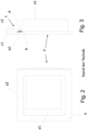
- FIG 2 is a view of a built-in element a according to the prior art.
- the built-in element a essentially consists of a square body a1 with a rear wall and a square frame a2 attached to the front of the body a1 and projecting outwards.
- the Figure 3 shows a side view of Figure 2 , wherein additionally a part of a drywall c with an outer drywall panel c1 and an inner drywall panel c2 is shown at the top.
- a two-stepped recess b is cut into the drywall c, wherein in the inner drywall panel c2 the dimensions of the recess b are adapted to an outer circumference of the body a1 and in the outer drywall panel c1 the dimensions of the recess b are adapted to an outer circumference of the frame a2.
- an adhesive d is applied to the inner drywall panel c2
- the built-in element a is inserted into the recess b
- the back of the frame a2 comes into contact with the adhesive d
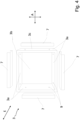
- FIG 4 is an exploded view of a built-in element 3 according to the invention with several mounting parts 7, which serve to fix the built-in element 3 in a recess 8 (see Figure 5 ) during assembly in an intermediate state and a fastening state in an installation direction E, but only in alignment directions A perpendicular to the installation direction, clamped but movable or stiffly movable.
- the alignment directions A run within the plane of a front side 2a of the drywall 2 and thus point up, down, right or left, or a mixture of these.
- the installation element 3 has a rectangular, in particular square, cross-section, and consists of four flat and rectangular wall parts 3a, which are connected to one another in a frame-like manner to form a type of body or cabinet body. If required, the installation element 3 is closed at the back with a rear wall 3b, which is attached to the wall parts 3a.
- the four assembly parts 7 are each designed as U-profiles, in particular standardized UW profiles, or angles.
- the assembly parts 7 have a maximum length that corresponds to the length of the wall parts 3a.
- the length of the assembly parts 7 is only 60 to 90% of the length of the wall parts 3a.
- the material thickness of the assembly parts 7 is not less than 0.4 mm and not more than 1.0 mm and can therefore be easily manufactured using hand shears.
- the Figure 4 It can be seen that two holes 9 are already provided in each of the wall parts 3a in order to attach the mounting parts 7 to an outer side 3c of the wall parts 3a during the assembly of the installation element 3 or to pull them towards them and attach them.
- the installation element 3 and the four mounting parts 7 form a kit and together form a fastening frame, whereby the individual drywall panels 7 are only connected to one another via the installation element 3. Overall, the fastening frame is therefore made up of several parts.
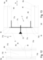
- the Figure 5 shows a plan view of a horizontal section through a built-in element 3 in an adjacent drywall 2.
- the drywall 2 is a so-called double-planked drywall 2 with an inner drywall panel 4i and an outer drywall panel 4a.
- the double-planked drywall 2 can be a part or a side of a wall or a front wall.
- a rectangular Recess 8 has been cut.
- the dimensions of the recess 8, in particular its width X and its height H, are adapted to the installation element 3 to be installed, in particular its width Y and length Z.
- the recess 8 is thus essentially rectangular or square. In principle, polygonal, round or oval are also conceivable.
- the width Y and the length Z of the installation element 3 are each approximately 5 to 30 mm smaller than the width X and the height H. From the Figure 5 it can be seen that in a first assembly step, all four assembly parts 7, of which a right and a left assembly part 7 are shown, are inserted with a leg 7a between the inner drywall panel 4i and the outer drywall panel 4a against the resistance of the inner drywall panel 4i and the outer drywall panel 4a in an inserted state.
- the leg 7a is not fastened between the inner drywall panel 4i and the outer drywall panel 4a, but remains clamped between the inner drywall panel 4i and the outer drywall panel 4a and can be moved.
- the assembly part 7 is thus fastened in the drywall 2 without additional holding parts.
- Each of the U-shaped assembly parts 7 consists of opposite first and second legs 7a, 7b and a web 7c connecting the two legs 7a, 7b preferably at right angles. If the mounting part 7 is designed as an angle, the web 7c and the legs 7a are of course connected to one another at right angles.
- the legs 7a are preferably inserted between the inner drywall panel 4i and the outer drywall panel 4a so that in the subsequent assembly step the installation element 3 can just about be pushed in between the four mounting parts 7 but is already easily held by the mounting parts 7 in the drywall 2. This facilitates subsequent alignment of the installation element 3 in the installation direction E in the drywall 2.
- the next assembly step involves loosely inserting the installation element 3 into the recess 8 or between the four assembly parts 7.
- the installation element 3 is then inserted in relation to the installation direction E in the desired installation depth. to the drywall 2, so that preferably the frontal cutting surfaces of the wall parts 3a are flush with a front surface of the drywall 2 or the outer drywall panel 4a.
- the installation element 3 protrudes from the drywall 2.
- each of the four wall parts 3a is screwed to the adjacent mounting part 7 in an intermediate state using screws 11, preferably construction screws, inserted into the corresponding holes 9 provided in the wall parts 3a.
- the installation element 3 in the intermediate state is aligned horizontally and vertically in the recess 8, preferably by means of hammer blows, in the alignment direction A.
- the mounting parts 7 are screwed to the drywall panels 4a, 4i in a fastening state.
- the screws 11 thus extend from the outside through the outer drywall panel 4a, the leg 7a and the inner drywall panel 4i.
- the position of the installation element 3 is fixed in relation to the alignment to the drywall 2 or to the edge 4r of the outer drywall panel 4a.
- the existing gap 10 between the outer side 3c of the respective wall part 3a and the edge 4r of the outer drywall panel 4a is closed with an adhesive filler.
- FIG 6 is a detail enlargement of Figure 5 from the area of a connection of the installation element 3 to the drywall 2 by means of the mounting parts 7.
- the assembly part 7 shown is already connected to the wall part 3a of the installation element 3 in the intermediate state via the two screws 11.
- the assembly part 7 already rests on the outside 3c of the wall part 3a.
- a gap can be seen, which was only shown in the drawing to give the leg 7a of the mounting part 7 space for insertion.
- the inner drywall panel 4i and the outer drywall panel 4a lie close to one another and the space or gap 10 at the edge between the inner drywall panel 4i and the outer drywall panel 4a only arises when the leg 7a is inserted through elastic deformation of the inner drywall panel 4i and the outer drywall panel 4a.
- the installation element 3 remains displaceable in the alignment direction A via the inserted mounting part 7, but is in installation direction E.
- the gap 10 between the wall part 3a and the outer drywall panel 4a can be closed in a later process step using an adhesive filler.
- the gap 10 or the position of the installation element 3 in the drywall 2 in the alignment direction A can also continue to be variably changed.
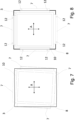
- FIG 7 is a view of an installation element 3 installed in a drywall 2 but not aligned in the intermediate state.
- the drywall 2 is only indicated by the recess 8.
- the mounting parts 7 are already attached to the outside 3c of the installation element 3.
- the legs 7a of the mounting parts 7 are already inserted into the drywall 2 and attached to the installation element 3.
- the installation element 3 is thus fixed in the installation direction E in the drywall 2 but can still be moved in the alignment direction A.
- FIG 8 shows a view according to Figure 7 , but the installation element 3 is now aligned vertically and horizontally in the alignment direction A in the intermediate state.
- the assembly parts 7 are fastened to the drywall 2 in the fastening state by screws 12 inserted in the installation direction E. Two screws 12 are provided for each assembly part 7.
- FIG. 9 A perspective view of the installation element 3 installed and aligned in the drywall 2 according to Figure 8 is in the Figure 9 shown.
- the drywall 2 can again be seen essentially via the recess 8, which is adjacent to the outer drywall 4a.
- the gap 10 running between the drywall 2 and the installation element 3 can also be clearly seen in the fastening state.
- the assembly elements 7, which are already arranged behind the drywall in this installation situation, are shown by dash-dotted lines.
- the Figure 10 shows an enlarged detail of a plan view of a horizontal section through one side of a built-in element 3 with an adjacent drywall 2 in the intermediate state.
- the drywall 2 is designed as a wall and is thus paneled on its two opposite sides with an inner drywall panel 4i and an outer drywall panel 4a.
- the width of the mounting part 7 or the distance between its two legs 7a, 7b is thus designed such that the legs 7a, 7b can be inserted opposite one another between the outer drywall panel 4a and the inner drywall panel 4i.
- the distance between the opposite legs 7a, 7b of the mounting part 7 is therefore preferably identical to the width of the stud profiles 5 in the drywall 2 plus twice the thickness of a drywall panel 4a, 4i.
- the built-in element 3 can thus be designed as a window element, as a hatch or as a cupboard or shelf accessible from both sides.
- the mounting parts 7 in the double-paneled drywall 2 face the respective undersides of the wall parts 3a of the built-in element.
- FIG. 11 a perspective view of a mounting part 7' is shown in a second embodiment.
- This mounting part 7' is also designed as a U-profile with a first leg 7'a, a second leg 7'b and a web 7'c.
- two arms 7'd are arranged on this mounting part 7' at its opposite ends 7'e, which extend laterally and in the plane of the web 7'c as well as away from the web 7'c when viewed in the longitudinal direction of the mounting part 7'.
- the arms 7'd each have a length of 5 mm to 20 mm and are in any case shorter than the thickness of the respective drywall panels 4a, 4i of the drywall 2.
- the arms 7'd are intended to prevent the mounting part 7' from being able to penetrate too far into the cavity between the opposite sides of a drywall 2 with corresponding drywall panels 4a, 4i.
- the Figure 12 shows a view of a mounting part 7' installed in a recess 8 of a drywall 2 according to Figure 11 in the intermediate state.
- the Figure 12 The installation situation shown corresponds essentially to the one described above.
- the drywall 2 is designed as a wall and is thus covered on its two opposite sides with an inner drywall panel 4i and an outer drywall panel 4a.
- the holding element 7' is thus designed in its width or with regard to the distance between its two legs 7'a, 7'b in such a way that the legs 7'a, 7'b can be inserted opposite each other between the two inner drywall panels 4i on their inner sides 4ii.
- the mounting part 7' is thus held by the legs 7'a, 7'b clamped between the inner sides 4ii of the opposite inner drywall panels 4i.
- the web 7c prevents the mounting part 7 from being able to dip too far into the cavity between the opposite sides of a drywall 2 with corresponding drywall panels 4a, 4i, in particular when screwing on the wall parts 3a.
- this task is performed by the arms 7'd, which come to rest in the ends of the inner drywall panels 4i and also the outer drywall panel 4a that delimit the recess 8.
- the arms 7'd prevent the wall parts 4a from being pushed between the inner drywall panels 4i by the pressure of the screw 11 when screwing on the mounting parts 7'.
- the built-in element 3 can also be designed as a window element, as a hatch or as a cupboard or shelf accessible from both sides.
- the Figure 13 shows an enlarged detail of a plan view of a horizontal section through one side of a built-in element 3 with a mounting part 7' and an adjacent drywall 2 in the intermediate state.
- This also clearly shows that on the one hand the legs 7'a, 7 ⁇ b of the mounting part 7' are clamped against the inner sides 4ii of the two inner drywall panels 4i and on the other hand the arms 7'd are supported on the ends of the inner drywall panels 4i and, if necessary, the outer drywall panels 4a that delimit the recess 8 in the event that the gap 10 is minimized during the assembly process.
- the distance between the opposite legs 7'a, 7 ⁇ b of the mounting part 7 is therefore preferably identical to the width of the stud profiles 5 in the drywall 2 or the distance between the inner drywall panels 4i.
Landscapes
- Engineering & Computer Science (AREA)
- Architecture (AREA)
- Civil Engineering (AREA)
- Structural Engineering (AREA)
- Physics & Mathematics (AREA)
- Electromagnetism (AREA)
- Connection Of Plates (AREA)
Applications Claiming Priority (1)
| Application Number | Priority Date | Filing Date | Title |
|---|---|---|---|
| DE202023000199 | 2023-01-31 |
Publications (1)
| Publication Number | Publication Date |
|---|---|
| EP4411085A1 true EP4411085A1 (fr) | 2024-08-07 |
Family
ID=89772248
Family Applications (1)
| Application Number | Title | Priority Date | Filing Date |
|---|---|---|---|
| EP24154765.2A Withdrawn EP4411085A1 (fr) | 2023-01-31 | 2024-01-30 | Agencement doté d'éléments de construction agencés dans une cloison sèche et procédé de fixation associé |
Country Status (1)
| Country | Link |
|---|---|
| EP (1) | EP4411085A1 (fr) |
Citations (2)
| Publication number | Priority date | Publication date | Assignee | Title |
|---|---|---|---|---|
| EP1840288B1 (fr) | 2006-03-29 | 2015-04-01 | TREL Systems AG | Agencement destiné au stockage d'objets à l'aide d'éléments de construction dans un mur constitué d'éléments préfabriqués et son procédé de fixation |
| EP3145365B1 (fr) * | 2014-05-20 | 2020-01-15 | Uwe Kirschenmann | Distributeur de lotion pour salles de bains et locaux sanitaires |
-
2024
- 2024-01-30 EP EP24154765.2A patent/EP4411085A1/fr not_active Withdrawn
Patent Citations (2)
| Publication number | Priority date | Publication date | Assignee | Title |
|---|---|---|---|---|
| EP1840288B1 (fr) | 2006-03-29 | 2015-04-01 | TREL Systems AG | Agencement destiné au stockage d'objets à l'aide d'éléments de construction dans un mur constitué d'éléments préfabriqués et son procédé de fixation |
| EP3145365B1 (fr) * | 2014-05-20 | 2020-01-15 | Uwe Kirschenmann | Distributeur de lotion pour salles de bains et locaux sanitaires |
Similar Documents
| Publication | Publication Date | Title |
|---|---|---|
| DE3726255C2 (de) | Trennwand | |
| EP3536873B1 (fr) | Élément profilé et système de façade comprenant un tel profilé | |
| EP1870529B1 (fr) | Mur/ensemble de coffre pour une construction de cadre | |
| EP1840288B1 (fr) | Agencement destiné au stockage d'objets à l'aide d'éléments de construction dans un mur constitué d'éléments préfabriqués et son procédé de fixation | |
| EP3115521B1 (fr) | Armature et systeme d'armature destine a la liaison reversible d'elements plats et systeme de paroi verticale modulaire | |
| AT10445U1 (de) | Profilrahmenkonstruktion mit einem grundprofil auf einem pfosten- oder riegelprofil aus holz sowie führungseinrichtung zum eintreiben von nägeln | |
| DE3804660C2 (fr) | ||
| DE19649388A1 (de) | Stahlbauverbindungssystem | |
| EP4411085A1 (fr) | Agencement doté d'éléments de construction agencés dans une cloison sèche et procédé de fixation associé | |
| EP2644818A1 (fr) | Pièce de liaison | |
| CH711428B1 (de) | Modulares System für Schränke und/oder Regale. | |
| AT12936U1 (de) | Bausatz zur herstellung eines holzhauses in vollholz-blockbauweise sowie daraus hergestelltes holzhaus | |
| EP2083127B1 (fr) | Tête de liaison et système destiné à l'établissement de structures | |
| AT526842B1 (de) | Rechtwinkelige Fachwerk-Struktur mit hoher Stabilität und Gestaltungsfreiheit, als Raumgliederung oder Regal | |
| EP4289310A1 (fr) | Élément de montage pour stocker des objets dans une cloison de construction sèche et agencement doté de celui-ci | |
| DE102022131160A1 (de) | Einbauelement zur Aufbewahrung von Gegenständen in einer Trockenbauwand und Anordnung hiermit | |
| EP2486825B1 (fr) | Agencement de fixation | |
| EP4265152A1 (fr) | Armoire d'angle avec portes coulissantes | |
| EP1717452A1 (fr) | Dispositif de liaison de deux éléments de construction | |
| AT16045U1 (de) | Flächiger Verbund aus Holzelementen | |
| EP3290617B1 (fr) | Console en u avec plaques de côté rétractables | |
| CH706314A2 (de) | Verbindungsteil. | |
| DE102009060405A1 (de) | Zweiteiliger Verbindungsbeschlag | |
| AT524508A1 (de) | Bausatz für ein Gerätehaus | |
| AT17369U1 (de) | Bausatz für ein Gerätehaus |
Legal Events
| Date | Code | Title | Description |
|---|---|---|---|
| PUAI | Public reference made under article 153(3) epc to a published international application that has entered the european phase |
Free format text: ORIGINAL CODE: 0009012 |
|
| STAA | Information on the status of an ep patent application or granted ep patent |
Free format text: STATUS: THE APPLICATION HAS BEEN PUBLISHED |
|
| AK | Designated contracting states |
Kind code of ref document: A1 Designated state(s): AL AT BE BG CH CY CZ DE DK EE ES FI FR GB GR HR HU IE IS IT LI LT LU LV MC ME MK MT NL NO PL PT RO RS SE SI SK SM TR |
|
| STAA | Information on the status of an ep patent application or granted ep patent |
Free format text: STATUS: THE APPLICATION IS DEEMED TO BE WITHDRAWN |
|
| 18D | Application deemed to be withdrawn |
Effective date: 20250208 |