EP4411145A1 - Wasserpumpe mit eingebauter batterie - Google Patents
Wasserpumpe mit eingebauter batterie Download PDFInfo
- Publication number
- EP4411145A1 EP4411145A1 EP23174903.7A EP23174903A EP4411145A1 EP 4411145 A1 EP4411145 A1 EP 4411145A1 EP 23174903 A EP23174903 A EP 23174903A EP 4411145 A1 EP4411145 A1 EP 4411145A1
- Authority
- EP
- European Patent Office
- Prior art keywords
- battery compartment
- battery
- water pump
- built
- pump body
- Prior art date
- Legal status (The legal status is an assumption and is not a legal conclusion. Google has not performed a legal analysis and makes no representation as to the accuracy of the status listed.)
- Granted
Links
Images




Classifications
-
- F—MECHANICAL ENGINEERING; LIGHTING; HEATING; WEAPONS; BLASTING
- F04—POSITIVE - DISPLACEMENT MACHINES FOR LIQUIDS; PUMPS FOR LIQUIDS OR ELASTIC FLUIDS
- F04D—NON-POSITIVE-DISPLACEMENT PUMPS
- F04D13/00—Pumping installations or systems
- F04D13/02—Units comprising pumps and their driving means
- F04D13/06—Units comprising pumps and their driving means the pump being electrically driven
- F04D13/066—Floating-units
-
- F—MECHANICAL ENGINEERING; LIGHTING; HEATING; WEAPONS; BLASTING
- F04—POSITIVE - DISPLACEMENT MACHINES FOR LIQUIDS; PUMPS FOR LIQUIDS OR ELASTIC FLUIDS
- F04D—NON-POSITIVE-DISPLACEMENT PUMPS
- F04D13/00—Pumping installations or systems
- F04D13/02—Units comprising pumps and their driving means
- F04D13/06—Units comprising pumps and their driving means the pump being electrically driven
- F04D13/068—Battery powered
-
- F—MECHANICAL ENGINEERING; LIGHTING; HEATING; WEAPONS; BLASTING
- F04—POSITIVE - DISPLACEMENT MACHINES FOR LIQUIDS; PUMPS FOR LIQUIDS OR ELASTIC FLUIDS
- F04D—NON-POSITIVE-DISPLACEMENT PUMPS
- F04D13/00—Pumping installations or systems
- F04D13/02—Units comprising pumps and their driving means
- F04D13/06—Units comprising pumps and their driving means the pump being electrically driven
- F04D13/0686—Mechanical details of the pump control unit
-
- F—MECHANICAL ENGINEERING; LIGHTING; HEATING; WEAPONS; BLASTING
- F04—POSITIVE - DISPLACEMENT MACHINES FOR LIQUIDS; PUMPS FOR LIQUIDS OR ELASTIC FLUIDS
- F04D—NON-POSITIVE-DISPLACEMENT PUMPS
- F04D15/00—Control, e.g. regulation, of pumps, pumping installations or systems
- F04D15/02—Stopping of pumps, or operating valves, on occurrence of unwanted conditions
- F04D15/0281—Stopping of pumps, or operating valves, on occurrence of unwanted conditions responsive to a condition not otherwise provided for
-
- F—MECHANICAL ENGINEERING; LIGHTING; HEATING; WEAPONS; BLASTING
- F04—POSITIVE - DISPLACEMENT MACHINES FOR LIQUIDS; PUMPS FOR LIQUIDS OR ELASTIC FLUIDS
- F04D—NON-POSITIVE-DISPLACEMENT PUMPS
- F04D29/00—Details, component parts, or accessories
- F04D29/40—Casings; Connections of working fluid
- F04D29/42—Casings; Connections of working fluid for radial or helico-centrifugal pumps
- F04D29/426—Casings; Connections of working fluid for radial or helico-centrifugal pumps especially adapted for liquid pumps
-
- Y—GENERAL TAGGING OF NEW TECHNOLOGICAL DEVELOPMENTS; GENERAL TAGGING OF CROSS-SECTIONAL TECHNOLOGIES SPANNING OVER SEVERAL SECTIONS OF THE IPC; TECHNICAL SUBJECTS COVERED BY FORMER USPC CROSS-REFERENCE ART COLLECTIONS [XRACs] AND DIGESTS
- Y02—TECHNOLOGIES OR APPLICATIONS FOR MITIGATION OR ADAPTATION AGAINST CLIMATE CHANGE
- Y02E—REDUCTION OF GREENHOUSE GAS [GHG] EMISSIONS, RELATED TO ENERGY GENERATION, TRANSMISSION OR DISTRIBUTION
- Y02E60/00—Enabling technologies; Technologies with a potential or indirect contribution to GHG emissions mitigation
- Y02E60/10—Energy storage using batteries
Definitions
- the present disclosure relates to the technical field of water pump structures, and in particular, to a water pump with a built-in battery.
- a water pump is a device that transports or pressurizes a liquid, and transmits the mechanical energy of a prime mover or other external energy to the liquid to increase the energy of the liquid.
- the water pump can also transport gas mixtures and liquids containing suspended solids.
- Cid patent CN214331003U discloses a fixing structure for a lithium battery-powered submersible pump, including a housing and a base connected through screws.
- a motor is provided on one side in the housing, and an impeller is provided at a corresponding position in the base.
- a battery compartment is provided on the other side in the housing.
- a plurality of axial limiting ribs are circumferentially arranged on an inner wall of the battery compartment, two support plates at a certain interval are provided at a top of the battery compartment, and two opposite battery racks are provided inside the battery compartment.
- a certain number of batteries are mounted between the battery racks, and support pieces are respectively provided at upper ends of the battery racks.
- An opening is formed in the base located below the battery compartment, and a battery compartment cover is provided in the opening.
- a pressing ring is sleeved on an outer wall of the battery compartment cover.
- a sealing ring is provided between a top of the pressing ring and the battery compartment cover, and a plurality of screw holes are circumferentially arranged at a bottom of the pressing ring. The pressing ring and the base are connected through screws.
- the opening of the battery compartment is formed below the battery compartment, and the battery compartment cover is disposed on the opening, such that when the submersible pump is in use, the weight of the batteries is concentrated on the battery compartment cover at the opening, and there is a risk of deformation and liquid infiltration into the battery compartment.
- the present disclosure provides a water pump with a built-in battery capable of preventing a liquid from penetrating into a battery compartment, such that a battery pack and an interface thereof in the battery compartment do not need to be additionally designed with waterproof performance, and the water pump is safer and lower in cost.
- a water pump with a built-in battery including a pump body, where
- a guide groove and a contact terminal are provided in the battery compartment
- the battery pack is slidably connected and detachably mounted in the battery compartment through cooperation between the guide piece and the guide groove. Moreover, the battery pack is further electrically connected to the pump body through electric connection between the contact terminal and the output groove, thereby powering the pump body.
- the battery compartment cover is fastened to the battery compartment; and a sealing ring is further sleeved on the battery compartment cover and configured to improve sealing performance between the battery compartment cover and the battery compartment.
- the sealing ring is further configured to improve the sealing performance between the battery compartment and the battery compartment cover.
- the water pump can also prevent, through the sealing ring, a liquid from penetrating into the battery compartment.
- control panel includes a wireless module and is wirelessly connected to a remote controller through the wireless module.
- the wireless module can achieve the remote control of the start and stop of the water pump or other functions.
- a connector is provided between the remote controller and the handle, and the remote controller is detachably connected to the handle through the connector.
- the remote controller When the remote controller is needed, the remote controller can be detached from the pump body for use; and when the remote controller is not needed, the remote controller can be stored and connected to the pump body to avoid missing.
- the connector is a magnetic adsorption member; and the remote controller is adsorbed to the handle through the magnetic adsorption member.
- the connector includes a limiting groove; and the limiting groove is formed in a side surface of the handle, and the remote controller is slidably connected and limited in the limiting groove.
- the water pump further includes a safety switch, where
- the safety switch can ensure that the water pump works only when the battery compartment cover is connected to the battery compartment, thereby further preventing the water pump from starting to work when the battery compartment and the battery compartment cover are not completely closed, resulting in burnout of the water pump due to a short circuit caused by liquid leakage in the battery compartment.
- the safety switch is a magnetic sensor
- the battery pack is provided with a plurality of batteries, and the batteries are lithium batteries.
- the lithium batteries have the advantages of high energy ratio, long service life, high power tolerance, light weight, environmental protection and the like.
- the pump body further includes an impeller and a diffusion chamber
- a floating structure is further connected to the pump body.
- the floating structure includes a floating member and a hinge member, and the hinge member is configured to hinge the floating member to a side surface of the pump body.
- the floating structure can float the water pump on a liquid surface, and the floating member is rotatably hinged to the pump body, such that the pump body is convenient to store and carry when not in use.
- the floating member includes a float and a housing that are in an integrated structure; and alternatively, the floating member includes a float and a housing that are in a split structure, where the float is connected into the housing; and one side of the housing is connected to the hinge member, and the other opposite side of the housing is fastened to the pump body.
- the hinge member includes a fixed member provided on the side surface of the pump body and a movable member connected to the housing;
- the limiting grid plate and the limiting plane are interacted to limit the rotation angle of the floating member, to ensure a maximum contact area between the float and the liquid surface at this time, thereby ensuring a maximum buoyancy is provided to the water pump.
- the battery compartment cover of the pump body is disposed at the top of the battery compartment.
- the junction between the battery compartment and the battery compartment cover is located the upper part of the pump body, and the battery pack does not exert a force on the battery compartment cover, thereby preventing the liquid from penetrating into the battery compartment.
- the water pump can use a general battery pack and a connector of the battery pack, and does not need to be additionally designed with waterproofness.
- the handle is disposed on the battery compartment cover, it is convenient for a user to disassemble and mount the battery compartment cover through the handle, and it is also convenient for the user to lift and carry the water pump through the handle.
- control panel and the battery compartment cover are respectively disposed at the top end of the mounting cavity and the top end of the battery compartment, which can avoid positional conflicts between the handle and the control panel, such that the use is more convenient.
- cord length of the electrical connection between the control panel and the motor and between the battery compartment and the motor can also be shortened, thereby making the overall circuit structure more compact.
- the floating structure can float the water pump on the liquid surface, thereby further preventing the liquid from leaking into the battery compartment, also preventing possible blocking of the water inlet because the water pump sinks to the bottom, and improving the liquid pumping efficiency.
- central In the description of the present disclosure, it should be noted that terms “central”, “longitudinal”, “transverse”, “length”, “width”, “thickness”, “upper”, “lower”, “front”, “back”, “left”, “right”, “vertical”, “horizontal”, “top”, “bottom”, “inner”, “outer”, “clockwise”, “anticlockwise” and the like, are used to indicate orientations or position relationships shown in accompanying drawings. It should be noted that these terms are merely intended to facilitate a simple description of the present disclosure, rather than to indicate or imply that the mentioned apparatus or elements must have the specific orientation or be constructed and operated in the specific orientation. Therefore, these terms may not be construed as a limitation to the present disclosure.
- first and second are merely intended for a purpose of description, and shall not be understood as an indication or implication of relative importance or implicit indication of a quantity of indicated technical features. Therefore, the features defined by “first” and “second” can explicitly or implicitly include one or more features. In the description of the present disclosure, "a plurality of means two or more, unless otherwise specifically defined.
- connection may be a fixed connection, a removable connection, or an integral connection; may be a mechanical connection, an electrical connection, or mutual communication; may be a direct connection or an indirect connection via an intermediate medium; or may be an interconnection or an interaction relationship between two elements.
- connection may be a fixed connection, a removable connection, or an integral connection; may be a mechanical connection, an electrical connection, or mutual communication; may be a direct connection or an indirect connection via an intermediate medium; or may be an interconnection or an interaction relationship between two elements.
- a first feature when it is described that a first feature is “above” or “under” a second feature, it may indicate that the first feature is in direct contact with the second feature, or that the first feature and the second feature are not in direct contact with each other but are in contact via another feature between them.
- that the first feature is “over”, “above”, and “on” the second feature includes that the first feature is directly above and diagonally above the second feature, or simply indicates that a horizontal height of the first feature is larger than that of the second feature.
- the case where the first feature is "beneath”, “below”, and “under” the second feature includes that the first feature is directly below and diagonally below the second feature, or simply indicates that the altitude of the first feature is lower than that of the second feature.
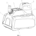
- this embodiment provides a water pump with a built-in battery.
- the water pump includes pump body 1. Battery compartment 2 and mounting cavity 15 are provided in the pump body 1, and are adjacent to each other but not communicated with each other. Motor 12 is mounted in the mounting cavity 15, and an output shaft of the motor 12 is connected to impeller 13. Water inlet 10 is formed in a bottom of the pump body 1, water outlet 11 is further formed in a top surface of the pump body 1, and a channel communicating the water inlet 10 and the water outlet 11 is further formed inside the pump body 1.
- the channel includes a pressurization area, diffusion chamber 14, and a conveying area connected in sequence. The pressurization area is communicated with the water inlet 10, the diffusion chamber 14 is located between the pressurization area and the conveying area, and the conveying area communicates the diffusion chamber 14 and the water outlet 11.
- the impeller 13 is located in the pressurization area. After entering the pressurization area through the water inlet 10, a liquid is pressurized under rotation of the impeller 13, is conveyed into the diffusion area for pressure release, reaches the water outlet 11 through the conveying area under the released pressure, and is finally discharged from the water outlet 11.
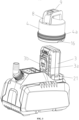
- Battery pack 3 is detachably connected into the battery compartment 2. Specifically, eight lithium batteries 3c connected in series are provided in the battery pack 3.
- Two guide grooves 2a are vertically arranged in the battery compartment 2 along a compartment wall direction, and each include a notch. Openings of the notches of the two guide grooves 2a are oppositely arranged, and the two guide grooves 2a are in parallel.
- Two guide pieces 3a matched with the guide grooves 2a are also provided at corresponding positions on a side surface of the battery pack 3. The guide pieces 3a and the guide grooves 2a are matched to form a limited connection. Through the limited connection, the battery pack 3 can slide up and down in the battery compartment 2. When the battery pack 3 slides to the bottom, the battery pack 3 is completely connected to the battery compartment 2.
- contact terminal 2b is further provided between the two guide grooves 2a and made of a conductive metal.
- output groove 3b is also formed between the two guide pieces 3a and provided with a contact chip. The contact chip is electrically connected to the lithium batteries 3c, and the lithium batteries 3c output, through the contact chip, power to other objects that are going to use the power.
- control panel 5 is electrically connected to the battery pack 3 through the battery compartment 2.
- An opening is formed in a top of the battery compartment 2 and configured to mount or take the battery pack 3 in or from the battery compartment 2.
- battery compartment cover 4 is connected to the opening and is a cylinder structure.
- Two fasteners 16 are symmetrically arranged at equal intervals at the bottom end of the outer peripheral surface of the battery compartment cover 4, and two fasteners 16 are also provided at corresponding positions on the inner peripheral surface of the opening of the battery compartment 2.
- the fasteners 16 on the battery compartment 2 and the fasteners 16 on the battery compartment cover 4 are matched with each other and opposite to each other, and the battery compartment 2 is fastened to the battery compartment cover 4 through the fasteners 16.
- sealing ring 4a is further circumferentially sleeved on the outer peripheral surface of the battery compartment cover 4, and is configured to reinforce the sealing performance when the battery compartment 2 is connected to the battery compartment cover 4 and prevent an external liquid from entering the battery compartment 2.
- the pump body 1 is provided with control panel 5.
- the control panel 5 is disposed on a top surface of the mounting cavity 15, and is electrically connected to the motor 12 and the contact terminal 2b of the battery compartment 2.
- the battery pack 3 powers the control panel 5 and the motor 12 through the battery compartment 2, and the control panel 5 controls on and off of the motor 12, thereby controlling on and off of the water pump.
- the present disclosure provides another embodiment on the basis of the above embodiment.
- Matching hole 21 is further formed in the pump body 1.
- the matching hole 21 is formed in the side of the pump body 1 distant from a water outlet hole, passes through the pump body 1, and extends into the battery compartment 2.
- Limiting hole 22 is formed in an outer surface of the battery compartment cover 4, the aperture of the limiting hole 22 is set to be equal to the aperture of the matching hole 21, and internal threads are respectively provided in the matching hole 21 and the limiting hole 22.
- a screw is mounted in the matching hole 21, and passes through the matching hole 21 to be threadedly connected into the limiting hole 22, thereby further fixing the battery compartment 2 and the battery compartment cover 4, avoiding looseness or positional deviations, and further avoiding the leakage of the liquid in the battery compartment 2.
- the present disclosure provides another embodiment on the basis of the above embodiment.
- a safety switch is further provided on the water pump with a built-in battery.
- the safety switch is disposed at a junction between the battery compartment cover 4 and the battery compartment 2, is electrically connected to the battery compartment 2, and is configured to turn on or off a circuit between the battery compartment 2 and the control panel 5.
- the safety switch is a magnetic sensor, and the magnetic sensor is a Hall switch.
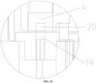
- the Hall switch includes Hall sensor 19 and sensing magnet 20.
- the Hall sensor 19 is disposed in a wall of the battery compartment 2, is set to be close to the junction between the battery compartment cover 4 and the battery compartment 2, and is electrically connected to the control panel 5.
- the Hall sensor 19, the battery compartment 2, and the control panel 5 are connected in series.
- the Hall sensor 19 is configured to turn on or off the circuit between the battery compartment 2 and the control panel 5.
- the sensing magnet 20 is mounted in the battery compartment cover 4. Specifically, the sensing magnet 20 is set to be close to the junction between the battery compartment cover 4 and the battery compartment 2.
- the Hall sensor 19 and the sensing magnet 20 are just opposite at this time, the Hall sensor 19 receives the action of the sensing magnet 20 to generate a potential difference, the battery compartment 2 and the control panel 5 are connected at this time, and the battery pack 3 powers the water pump through the battery compartment 2.
- the Hall sensor 19 and the sensing magnet 20 are not matched in position, the Hall sensor 19 does not generate a potential difference at this time, the battery compartment 2 and the control panel 5 are not connected, and the battery pack 3 does not power the battery compartment 2 at this time.
- the Hall switch can also be in signal connection with the control panel 5.
- the Hall sensor 19 and the sensing magnet 20 are just opposite at this time, and the Hall switch outputs a connection signal to the control panel 5.
- the control panel 5 receives the connection signal
- the battery pack 3 is electrically connected to the control panel 5, such that the battery pack 3 powers the control panel 5 and the batteries.
- the Hall switch outputs a non-connection signal to the control panel 5. After the control panel 5 receives the non-connection signal, the electric connection between the battery pack 3 and the control panel 5 is cut off or maintained.
- the safety switch may also be a pressure switch.
- the safety switch is a pressure switch
- a pressing member is provided on the battery compartment cover 4, and a contact member is provided in the battery compartment 2.
- the pressing member presses the contact member.
- the pressure switch transmits a signal to the control panel 5, and the control panel 5 controls that the circuit between the battery pack 3 and the control panel 5 is turned on.
- the battery pack 3, the pressure switch, and the control panel 5 are connected in series. When the pressure switch is turned on, the battery pack 3 is directly connected to the control panel 5.
- Setting the structure of the safety switch can ensure that the water pump is powered on only when the battery compartment 2 is completely connected to the battery compartment cover 4, to avoid burnout of the water pump due to a short circuit caused by liquid leakage in the battery compartment 2.
- the present disclosure provides another embodiment on the basis of the above embodiment.
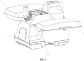
- This embodiment provides a floating structure applied to the water pump with a built-in battery described in any of the above embodiments.
- the floating structure includes floating members and a hinge member.
- Two floating members are provided on the pump body 1 and symmetrically arranged on opposite side surfaces of the pump body 1.
- Each floating member includes float 6 and housing 7.
- the float 6 may be a hollowed plastic block, or may be made of a floatable material. This embodiment does not define the material and structure of the float 6, and the float 6 in the present disclosure may be made of the floatable material in any prior art.
- the float 6 is fixed on the housing 7 by means of threaded connection.
- the housing 7 is hinged to a side surface of the pump body 1 by the hinge member.
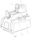
- the hinge member includes fixed member 18 and movable member 17.
- the fixed member 18 is fixedly connected to the side surface of the pump body 1, and the movable member 17 is mounted on a side of the housing 7.
- the side of the housing 7 is rotatably connected to the pump body 1 through the hinging between the movable member 17 and the fixed member 18; and through the hinging, the housing 7 can rotate on the pump body 1.
- a hook claw is provided on the opposite side of the housing 7, a hook groove is formed in a corresponding position of the pump body 1, and the hook claw and the hook groove are matched with each other and fastened.
- the housing 7 When the housing 7 is unfolded, the hook claw is separated from the hook groove, the housing 7 is rotated to the side surface of the pump body 1 through the hinging to be vertical, and at this time, the float 6 is located at the bottom end of the housing 7.
- the float 6 floats on the liquid surface, such that the pump body 1 floats on the liquid surface, and the opening of the battery compartment 2 is set to be higher than the liquid surface, thereby preventing the liquid from entering the battery compartment 2, and ensuring that the water inlet 10 at the bottom of the pump body 1 can sink into the liquid, without affecting the pumping function of the water pump.
- the housing 7 rotates on the pump body 1 through the hinge member at an angle of 0-135 degrees.
- expansion block 6a is provided on the side of the float 6 close to the hinge member.
- the expansion block 6a is set as a plane protruding from the housing 7, and is configured to increase the volume of the float 6, thereby increasing the displacement of the float 6, and increasing the buoyancy that can be obtained by the water pump.
- a groove configured to accommodate the expansion block 6a is formed in the side surface of the pump body 1. The groove is formed in the side of the side surface of the pump body 1 close to the water outlet 11. By setting at this position, the volume of the groove and the expansion block 6a can be increased as much as possible without affecting the mounting space of the impeller 13.
- the movable member 17 and the fixed member 18 are each composed of three parallel segments hinged to each other.
- the hinge structure can length and increase the contact area between the floating member and the pump body 1, thereby improving the connection stability of the floating member, and avoiding positional deviations thereof.
- the present disclosure provides another embodiment on the basis of the above embodiment.
- a wireless module is further provided in the control panel 5.
- the water pump further includes remote controller 9.
- the remote controller 9 is wirelessly connected to the control panel 5 through a wireless module.
- the remote controller 9 starts or stops the motor 12 by wirelessly connecting and remotely controlling the control panel 5, thereby controlling startup and stop of the water pump.
- This embodiment does not define the wireless connection mode, and any wireless connection and control mode existing in the prior art can be used in this implementation.
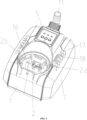
- Handle 8 is further provided on the top surface of the battery compartment cover 4, and is made of a magnetic metal.
- the handle 8 is made of heat-treated tempered martensitic stainless steel or anti-rust paint-coated metal iron, thereby ensuring good rust resistance while possessing a magnetic force.
- the handle 8 includes vertical plates provided on both sides and a chamber sunken between the vertical plates.
- a permanent magnet is mounted inside the remote controller 9.
- the permanent magnet is magnet 9a.
- the remote controller 9 can be adsorbed into the sunken chamber of the handle 8 through the magnet 9a.
- the handle 8 is made of a plastic material or other non-magnetic materials.
- a ferromagnet is provided on the handle 8, and the remote controller 9 is adsorbed on the ferromagnet of the handle 8 through the magnet 9a.
- the handle 8 is made of a plastic material or other non-magnetic materials.
- magnet 9a is provided on the handle 8.
- the remote controller 9 is provided with a ferromagnet or includes a housing made of a magnetic metal. The remote controller 9 is adsorbed on the magnet 9a of the handle 8.
- the remote controller 9 When remote wireless control for the water pump is needed, the remote controller 9 is removed from the handle 8. when the water pump needs to be stored, the remote controller 9 is magnetically adsorbed on the chamber of the handle 8 to avoid loss.
- the present disclosure provides another embodiment on the basis of the above embodiment.
- the handle 8 includes vertical plates provided on both sides and a chamber sunken between the vertical plates.
- Limiting groove 8a is formed between the vertical plate vertically arranged close to a side of the control panel 5 and the chamber, and is configured to accommodate the remote controller 9.
- the remote controller 9 is slidably connected into the limiting groove 8a.
- matching groove 8b is further formed in the vertical plate in which the limiting groove 8a is formed.
- Matching block 9b matched and connected to the matching groove 8b is provided on a side surface of the remote controller 9. Inclined surfaces are provided at both ends of the matching block 9b.
- the remote controller 9 slides in the limiting groove 8a, and the matching block 9b is matched in the matching groove 8b through the inclined surfaces, the remote controller 9 is fixed to the limiting groove 8a.
- the inclined surfaces are convenient for the matching block 9b to match with or leave the matching groove 8b.
- the remote controller 9 When remote wireless control for the water pump is needed, the remote controller 9 is slidably removed from the limiting groove 8a of the handle 8. when the water pump needs to be stored, the remote controller 9 is fixed in the limiting groove 8a through the cooperation between the matching block 9b and the matching groove 8b, thereby avoiding the loss of the remote controller 9.
- the present disclosure provides another embodiment on the basis of the above embodiment.
- Limiting grid plate 18a is provided on the fixed member 18, and includes a fitting surface in parallel to the side surface of the pump body 1 and in contact with the movable member 17.
- the movable member 17 includes movable curved surface 17a and limiting plane 17b adjacent to each other. When the floating member and the pump body 1 are closed, the movable curved surface 17a is in contact with the fitting surface of the limiting grid plate 18a at this time, and the limiting plane 17b is perpendicular to the side surface of the pump body 1.
- the movable curved surface 17a and the fitting surface of the limiting grid plate 18a are in contact and rotate, and as the rotation angle increases, the limiting plane 17b and the pump body 1 also tend to be parallel.
- the rotation angle is 90 degrees
- the movable curved surface 17a is separated from the fitting surface of the limiting grid plate 18a at this time, and the limiting plane 17b abuts against the fitting surface of the limiting grid plate 18a.
- the floating member reaches the limit of the rotation angle, and at this time, a plane where the float 6 is located is just perpendicular to the side surface of the pump body 1.
- the bottom surface of the float 6 is just completely fitted and in contact with the liquid surface, thereby ensuring that the float 6 floats on the liquid surface with the maximum area, such that the water pump possesses the maximum buoyancy.
- the angle of the floating member rotating on the pump body 1 through the hinge member ranges from 0 degree to 135 degrees.
- the present disclosure provides another embodiment on the basis of the above embodiment.
- the water pump with a built-in battery further includes a controller electrically connected to the control panel 5. Meanwhile, the battery pack 3 is electrically connected to the controller, and the motor 12 is electrically connected to the controller.
- the battery pack 3 is electrically connected to the control panel 5 through the controller, and the motor 12 is electrically connected to the control panel 5 through the controller.
- the controller is disposed in the mounting cavity and split from the control panel 5.
- a plurality of control buttons are provided on the control panel 5. When the buttons on the control panel 5 are pressed down, or the wireless module in the control panel 5 receives the signal of the remote controller 9, the control panel 5 outputs the signal to the controller, and the controller controls startup or stop of the motor 12 or performs a corresponding working behavior.
- the controller and the control panel 5 are integrally arranged, the controller is mounted inside the control panel 5, and the controller is a control module.
- a plurality of control buttons are provided on the control panel 5. When the buttons on the control panel 5 are pressed down, or the wireless module in the control panel 5 receives the signal of the remote controller 9, the control panel 5 outputs the signal to the control module, and the control module controls startup or stop of the motor 12 or performs a corresponding working behavior.
Landscapes
- Engineering & Computer Science (AREA)
- Mechanical Engineering (AREA)
- General Engineering & Computer Science (AREA)
- Structures Of Non-Positive Displacement Pumps (AREA)
Applications Claiming Priority (1)
| Application Number | Priority Date | Filing Date | Title |
|---|---|---|---|
| CN202310047141.8A CN116025573A (zh) | 2023-01-31 | 2023-01-31 | 一种电池内置式水泵 |
Publications (2)
| Publication Number | Publication Date |
|---|---|
| EP4411145A1 true EP4411145A1 (de) | 2024-08-07 |
| EP4411145B1 EP4411145B1 (de) | 2025-03-19 |
Family
ID=86079284
Family Applications (1)
| Application Number | Title | Priority Date | Filing Date |
|---|---|---|---|
| EP23174903.7A Active EP4411145B1 (de) | 2023-01-31 | 2023-05-23 | Wasserpumpe mit eingebauter batterie |
Country Status (2)
| Country | Link |
|---|---|
| EP (1) | EP4411145B1 (de) |
| CN (1) | CN116025573A (de) |
Citations (5)
| Publication number | Priority date | Publication date | Assignee | Title |
|---|---|---|---|---|
| US3015281A (en) * | 1960-02-23 | 1962-01-02 | Cederholm R F D 1 | Portable liquid pump |
| CH393093A (de) * | 1960-11-05 | 1965-05-31 | Flux Geraete Ges Mbh | Schwimmpumpe |
| WO2019149390A1 (en) * | 2018-02-01 | 2019-08-08 | Husqvarna Ab | Rain protection for battery of a submersible pump |
| CN214331003U (zh) | 2020-12-09 | 2021-10-01 | 利欧集团浙江泵业有限公司 | 一种锂电池潜水泵的固定结构 |
| CN216714736U (zh) * | 2022-01-18 | 2022-06-10 | 宁波辰威电机有限公司 | 漂浮泵 |
Family Cites Families (8)
| Publication number | Priority date | Publication date | Assignee | Title |
|---|---|---|---|---|
| DE102007017445C5 (de) * | 2007-04-02 | 2015-08-27 | Alfred Kärcher Gmbh & Co. Kg | Flüssigkeitspumpe |
| US8864476B2 (en) * | 2011-08-31 | 2014-10-21 | Flow Control Llc. | Portable battery operated bilge pump |
| CN208336311U (zh) * | 2018-05-24 | 2019-01-04 | 山东晨晖电子科技有限公司 | 一种智能水表电池仓正压密封结构 |
| CN109270876A (zh) * | 2018-11-20 | 2019-01-25 | 漳州高新区远见产业技术研究有限公司 | 一种控制装置及电子设备 |
| CN212725530U (zh) * | 2020-06-10 | 2021-03-16 | 安阳市美星蓄能有限责任公司 | 一种电池槽盖及铅酸蓄电池 |
| CN217309788U (zh) * | 2021-12-29 | 2022-08-30 | 浙江尊润婴童用品有限公司 | 一种锁扣运动水杯 |
| CN114718877B (zh) * | 2022-03-18 | 2025-01-07 | 大庆市天德忠石油科技有限公司 | 一种可对内部的泵压进行监控和调控的立式泥浆泵 |
| CN219795582U (zh) * | 2023-01-31 | 2023-10-03 | 宁波君禾智能科技有限公司 | 一种电池内置式水泵及水泵 |
-
2023
- 2023-01-31 CN CN202310047141.8A patent/CN116025573A/zh active Pending
- 2023-05-23 EP EP23174903.7A patent/EP4411145B1/de active Active
Patent Citations (5)
| Publication number | Priority date | Publication date | Assignee | Title |
|---|---|---|---|---|
| US3015281A (en) * | 1960-02-23 | 1962-01-02 | Cederholm R F D 1 | Portable liquid pump |
| CH393093A (de) * | 1960-11-05 | 1965-05-31 | Flux Geraete Ges Mbh | Schwimmpumpe |
| WO2019149390A1 (en) * | 2018-02-01 | 2019-08-08 | Husqvarna Ab | Rain protection for battery of a submersible pump |
| CN214331003U (zh) | 2020-12-09 | 2021-10-01 | 利欧集团浙江泵业有限公司 | 一种锂电池潜水泵的固定结构 |
| CN216714736U (zh) * | 2022-01-18 | 2022-06-10 | 宁波辰威电机有限公司 | 漂浮泵 |
Also Published As
| Publication number | Publication date |
|---|---|
| EP4411145B1 (de) | 2025-03-19 |
| CN116025573A (zh) | 2023-04-28 |
Similar Documents
| Publication | Publication Date | Title |
|---|---|---|
| US8894389B2 (en) | Rechargeable battery powered utility pump with series centrifugal pump configuration | |
| EP2594801B1 (de) | Mit einer wiederaufladbaren Batterie versorgte Pumpe mit Reihen-Zentrifugalpumpenkonfiguration | |
| US20190120233A1 (en) | Submersible pump | |
| EP4411145B1 (de) | Wasserpumpe mit eingebauter batterie | |
| US20190183099A1 (en) | Direct Current Pump | |
| CN216714736U (zh) | 漂浮泵 | |
| CN219795582U (zh) | 一种电池内置式水泵及水泵 | |
| CN218548623U (zh) | 一种防水壳和电池 | |
| CN212497733U (zh) | 可自动断电的移动底盘及机器人 | |
| CN116378966A (zh) | 一种集成充放气功能和循环过滤水功能的泵 | |
| CN210734443U (zh) | 一种电源盒 | |
| AU2025200853B2 (en) | Misting fan | |
| KR100617622B1 (ko) | 전선없는 수중펌프 | |
| CN218102619U (zh) | 一种电池供电装置 | |
| CN219344998U (zh) | 一种无刷水泵 | |
| CN224123945U (zh) | 一种能实现快速定位安装的储能柜底座 | |
| CN216932754U (zh) | 一种折叠式桶装水抽水机 | |
| CN219549089U (zh) | 一种可充电式微型直流隔膜潜水泵 | |
| CN214479737U (zh) | 一种便携式多功能电源设备 | |
| CN222936939U (zh) | 一种缺水保护水泵及控制电路 | |
| CN215379420U (zh) | 一种线控器快速拆装结构及热泵机组 | |
| CN216381748U (zh) | 一种水利工程施工防水排水装置 | |
| CN219622383U (zh) | 水循环过滤的充气泳池 | |
| TWI918572B (zh) | 可更換電池之電動打氣機 | |
| RU64715U1 (ru) | Переносной вентилятор ю.в. розенберга |
Legal Events
| Date | Code | Title | Description |
|---|---|---|---|
| PUAI | Public reference made under article 153(3) epc to a published international application that has entered the european phase |
Free format text: ORIGINAL CODE: 0009012 |
|
| STAA | Information on the status of an ep patent application or granted ep patent |
Free format text: STATUS: REQUEST FOR EXAMINATION WAS MADE |
|
| 17P | Request for examination filed |
Effective date: 20230523 |
|
| AK | Designated contracting states |
Kind code of ref document: A1 Designated state(s): AL AT BE BG CH CY CZ DE DK EE ES FI FR GB GR HR HU IE IS IT LI LT LU LV MC ME MK MT NL NO PL PT RO RS SE SI SK SM TR |
|
| GRAP | Despatch of communication of intention to grant a patent |
Free format text: ORIGINAL CODE: EPIDOSNIGR1 |
|
| STAA | Information on the status of an ep patent application or granted ep patent |
Free format text: STATUS: GRANT OF PATENT IS INTENDED |
|
| INTG | Intention to grant announced |
Effective date: 20241112 |
|
| GRAS | Grant fee paid |
Free format text: ORIGINAL CODE: EPIDOSNIGR3 |
|
| GRAA | (expected) grant |
Free format text: ORIGINAL CODE: 0009210 |
|
| STAA | Information on the status of an ep patent application or granted ep patent |
Free format text: STATUS: THE PATENT HAS BEEN GRANTED |
|
| AK | Designated contracting states |
Kind code of ref document: B1 Designated state(s): AL AT BE BG CH CY CZ DE DK EE ES FI FR GB GR HR HU IE IS IT LI LT LU LV MC ME MK MT NL NO PL PT RO RS SE SI SK SM TR |
|
| REG | Reference to a national code |
Ref country code: GB Ref legal event code: FG4D |
|
| REG | Reference to a national code |
Ref country code: CH Ref legal event code: EP |
|
| REG | Reference to a national code |
Ref country code: IE Ref legal event code: FG4D |
|
| REG | Reference to a national code |
Ref country code: DE Ref legal event code: R096 Ref document number: 602023002448 Country of ref document: DE |
|
| PG25 | Lapsed in a contracting state [announced via postgrant information from national office to epo] |
Ref country code: RS Free format text: LAPSE BECAUSE OF FAILURE TO SUBMIT A TRANSLATION OF THE DESCRIPTION OR TO PAY THE FEE WITHIN THE PRESCRIBED TIME-LIMIT Effective date: 20250619 |
|
| PG25 | Lapsed in a contracting state [announced via postgrant information from national office to epo] |
Ref country code: FI Free format text: LAPSE BECAUSE OF FAILURE TO SUBMIT A TRANSLATION OF THE DESCRIPTION OR TO PAY THE FEE WITHIN THE PRESCRIBED TIME-LIMIT Effective date: 20250319 |
|
| PGFP | Annual fee paid to national office [announced via postgrant information from national office to epo] |
Ref country code: DE Payment date: 20250519 Year of fee payment: 3 |
|
| REG | Reference to a national code |
Ref country code: LT Ref legal event code: MG9D |
|
| PG25 | Lapsed in a contracting state [announced via postgrant information from national office to epo] |
Ref country code: NO Free format text: LAPSE BECAUSE OF FAILURE TO SUBMIT A TRANSLATION OF THE DESCRIPTION OR TO PAY THE FEE WITHIN THE PRESCRIBED TIME-LIMIT Effective date: 20250619 |
|
| PG25 | Lapsed in a contracting state [announced via postgrant information from national office to epo] |
Ref country code: HR Free format text: LAPSE BECAUSE OF FAILURE TO SUBMIT A TRANSLATION OF THE DESCRIPTION OR TO PAY THE FEE WITHIN THE PRESCRIBED TIME-LIMIT Effective date: 20250319 |
|
| PG25 | Lapsed in a contracting state [announced via postgrant information from national office to epo] |
Ref country code: LV Free format text: LAPSE BECAUSE OF FAILURE TO SUBMIT A TRANSLATION OF THE DESCRIPTION OR TO PAY THE FEE WITHIN THE PRESCRIBED TIME-LIMIT Effective date: 20250319 |
|
| PG25 | Lapsed in a contracting state [announced via postgrant information from national office to epo] |
Ref country code: BG Free format text: LAPSE BECAUSE OF FAILURE TO SUBMIT A TRANSLATION OF THE DESCRIPTION OR TO PAY THE FEE WITHIN THE PRESCRIBED TIME-LIMIT Effective date: 20250319 Ref country code: GR Free format text: LAPSE BECAUSE OF FAILURE TO SUBMIT A TRANSLATION OF THE DESCRIPTION OR TO PAY THE FEE WITHIN THE PRESCRIBED TIME-LIMIT Effective date: 20250620 |
|
| REG | Reference to a national code |
Ref country code: NL Ref legal event code: MP Effective date: 20250319 |
|
| PG25 | Lapsed in a contracting state [announced via postgrant information from national office to epo] |
Ref country code: NL Free format text: LAPSE BECAUSE OF FAILURE TO SUBMIT A TRANSLATION OF THE DESCRIPTION OR TO PAY THE FEE WITHIN THE PRESCRIBED TIME-LIMIT Effective date: 20250319 |
|
| PG25 | Lapsed in a contracting state [announced via postgrant information from national office to epo] |
Ref country code: SE Free format text: LAPSE BECAUSE OF FAILURE TO SUBMIT A TRANSLATION OF THE DESCRIPTION OR TO PAY THE FEE WITHIN THE PRESCRIBED TIME-LIMIT Effective date: 20250319 |
|
| PG25 | Lapsed in a contracting state [announced via postgrant information from national office to epo] |
Ref country code: SM Free format text: LAPSE BECAUSE OF FAILURE TO SUBMIT A TRANSLATION OF THE DESCRIPTION OR TO PAY THE FEE WITHIN THE PRESCRIBED TIME-LIMIT Effective date: 20250319 |
|
| PG25 | Lapsed in a contracting state [announced via postgrant information from national office to epo] |
Ref country code: ES Free format text: LAPSE BECAUSE OF FAILURE TO SUBMIT A TRANSLATION OF THE DESCRIPTION OR TO PAY THE FEE WITHIN THE PRESCRIBED TIME-LIMIT Effective date: 20250319 Ref country code: PT Free format text: LAPSE BECAUSE OF FAILURE TO SUBMIT A TRANSLATION OF THE DESCRIPTION OR TO PAY THE FEE WITHIN THE PRESCRIBED TIME-LIMIT Effective date: 20250721 |
|
| PG25 | Lapsed in a contracting state [announced via postgrant information from national office to epo] |
Ref country code: PL Free format text: LAPSE BECAUSE OF FAILURE TO SUBMIT A TRANSLATION OF THE DESCRIPTION OR TO PAY THE FEE WITHIN THE PRESCRIBED TIME-LIMIT Effective date: 20250319 Ref country code: IT Free format text: LAPSE BECAUSE OF FAILURE TO SUBMIT A TRANSLATION OF THE DESCRIPTION OR TO PAY THE FEE WITHIN THE PRESCRIBED TIME-LIMIT Effective date: 20250319 |
|
| PG25 | Lapsed in a contracting state [announced via postgrant information from national office to epo] |
Ref country code: AT Free format text: LAPSE BECAUSE OF FAILURE TO SUBMIT A TRANSLATION OF THE DESCRIPTION OR TO PAY THE FEE WITHIN THE PRESCRIBED TIME-LIMIT Effective date: 20250319 |
|
| PG25 | Lapsed in a contracting state [announced via postgrant information from national office to epo] |
Ref country code: EE Free format text: LAPSE BECAUSE OF FAILURE TO SUBMIT A TRANSLATION OF THE DESCRIPTION OR TO PAY THE FEE WITHIN THE PRESCRIBED TIME-LIMIT Effective date: 20250319 Ref country code: CZ Free format text: LAPSE BECAUSE OF FAILURE TO SUBMIT A TRANSLATION OF THE DESCRIPTION OR TO PAY THE FEE WITHIN THE PRESCRIBED TIME-LIMIT Effective date: 20250319 |
|
| PG25 | Lapsed in a contracting state [announced via postgrant information from national office to epo] |
Ref country code: RO Free format text: LAPSE BECAUSE OF FAILURE TO SUBMIT A TRANSLATION OF THE DESCRIPTION OR TO PAY THE FEE WITHIN THE PRESCRIBED TIME-LIMIT Effective date: 20250319 |
|
| PG25 | Lapsed in a contracting state [announced via postgrant information from national office to epo] |
Ref country code: SK Free format text: LAPSE BECAUSE OF FAILURE TO SUBMIT A TRANSLATION OF THE DESCRIPTION OR TO PAY THE FEE WITHIN THE PRESCRIBED TIME-LIMIT Effective date: 20250319 |
|
| PG25 | Lapsed in a contracting state [announced via postgrant information from national office to epo] |
Ref country code: IS Free format text: LAPSE BECAUSE OF FAILURE TO SUBMIT A TRANSLATION OF THE DESCRIPTION OR TO PAY THE FEE WITHIN THE PRESCRIBED TIME-LIMIT Effective date: 20250719 |
|
| REG | Reference to a national code |
Ref country code: DE Ref legal event code: R097 Ref document number: 602023002448 Country of ref document: DE |
|
| PG25 | Lapsed in a contracting state [announced via postgrant information from national office to epo] |
Ref country code: DK Free format text: LAPSE BECAUSE OF FAILURE TO SUBMIT A TRANSLATION OF THE DESCRIPTION OR TO PAY THE FEE WITHIN THE PRESCRIBED TIME-LIMIT Effective date: 20250319 |
|
| PG25 | Lapsed in a contracting state [announced via postgrant information from national office to epo] |
Ref country code: LU Free format text: LAPSE BECAUSE OF NON-PAYMENT OF DUE FEES Effective date: 20250523 |
|
| PLBE | No opposition filed within time limit |
Free format text: ORIGINAL CODE: 0009261 |
|
| STAA | Information on the status of an ep patent application or granted ep patent |
Free format text: STATUS: NO OPPOSITION FILED WITHIN TIME LIMIT |
|
| REG | Reference to a national code |
Ref country code: CH Ref legal event code: L10 Free format text: ST27 STATUS EVENT CODE: U-0-0-L10-L00 (AS PROVIDED BY THE NATIONAL OFFICE) Effective date: 20260128 |
|
| REG | Reference to a national code |
Ref country code: BE Ref legal event code: MM Effective date: 20250531 |
|
| PG25 | Lapsed in a contracting state [announced via postgrant information from national office to epo] |
Ref country code: MC Free format text: LAPSE BECAUSE OF FAILURE TO SUBMIT A TRANSLATION OF THE DESCRIPTION OR TO PAY THE FEE WITHIN THE PRESCRIBED TIME-LIMIT Effective date: 20250319 |
|
| 26N | No opposition filed |
Effective date: 20251222 |
|
| PG25 | Lapsed in a contracting state [announced via postgrant information from national office to epo] |
Ref country code: IE Free format text: LAPSE BECAUSE OF NON-PAYMENT OF DUE FEES Effective date: 20250523 |
|
| PG25 | Lapsed in a contracting state [announced via postgrant information from national office to epo] |
Ref country code: BE Free format text: LAPSE BECAUSE OF NON-PAYMENT OF DUE FEES Effective date: 20250531 |
|
| PG25 | Lapsed in a contracting state [announced via postgrant information from national office to epo] |
Ref country code: FR Free format text: LAPSE BECAUSE OF NON-PAYMENT OF DUE FEES Effective date: 20250531 |