EP4411150B1 - Pince de fixation - Google Patents
Pince de fixation Download PDFInfo
- Publication number
- EP4411150B1 EP4411150B1 EP24152282.0A EP24152282A EP4411150B1 EP 4411150 B1 EP4411150 B1 EP 4411150B1 EP 24152282 A EP24152282 A EP 24152282A EP 4411150 B1 EP4411150 B1 EP 4411150B1
- Authority
- EP
- European Patent Office
- Prior art keywords
- support
- clamping
- fastening clamp
- connecting part
- leg
- Prior art date
- Legal status (The legal status is an assumption and is not a legal conclusion. Google has not performed a legal analysis and makes no representation as to the accuracy of the status listed.)
- Active
Links
Images


Classifications
-
- F—MECHANICAL ENGINEERING; LIGHTING; HEATING; WEAPONS; BLASTING
- F16—ENGINEERING ELEMENTS AND UNITS; GENERAL MEASURES FOR PRODUCING AND MAINTAINING EFFECTIVE FUNCTIONING OF MACHINES OR INSTALLATIONS; THERMAL INSULATION IN GENERAL
- F16B—DEVICES FOR FASTENING OR SECURING CONSTRUCTIONAL ELEMENTS OR MACHINE PARTS TOGETHER, e.g. NAILS, BOLTS, CIRCLIPS, CLAMPS, CLIPS OR WEDGES; JOINTS OR JOINTING
- F16B5/00—Joining sheets or plates, e.g. panels, to one another or to strips or bars parallel to them
- F16B5/06—Joining sheets or plates, e.g. panels, to one another or to strips or bars parallel to them by means of clamps or clips
- F16B5/0607—Joining sheets or plates, e.g. panels, to one another or to strips or bars parallel to them by means of clamps or clips joining sheets or plates to each other
- F16B5/0621—Joining sheets or plates, e.g. panels, to one another or to strips or bars parallel to them by means of clamps or clips joining sheets or plates to each other in parallel relationship
- F16B5/0635—Joining sheets or plates, e.g. panels, to one another or to strips or bars parallel to them by means of clamps or clips joining sheets or plates to each other in parallel relationship fastened over the edges of the sheets or plates
-
- F—MECHANICAL ENGINEERING; LIGHTING; HEATING; WEAPONS; BLASTING
- F24—HEATING; RANGES; VENTILATING
- F24S—SOLAR HEAT COLLECTORS; SOLAR HEAT SYSTEMS
- F24S25/00—Arrangement of stationary mountings or supports for solar heat collector modules
- F24S25/60—Fixation means, e.g. fasteners, specially adapted for supporting solar heat collector modules
- F24S25/63—Fixation means, e.g. fasteners, specially adapted for supporting solar heat collector modules for fixing modules or their peripheral frames to supporting elements
- F24S25/634—Clamps; Clips
-
- F—MECHANICAL ENGINEERING; LIGHTING; HEATING; WEAPONS; BLASTING
- F24—HEATING; RANGES; VENTILATING
- F24S—SOLAR HEAT COLLECTORS; SOLAR HEAT SYSTEMS
- F24S25/00—Arrangement of stationary mountings or supports for solar heat collector modules
- F24S25/60—Fixation means, e.g. fasteners, specially adapted for supporting solar heat collector modules
- F24S25/63—Fixation means, e.g. fasteners, specially adapted for supporting solar heat collector modules for fixing modules or their peripheral frames to supporting elements
- F24S25/634—Clamps; Clips
- F24S25/636—Clamps; Clips clamping by screw-threaded elements
-
- Y—GENERAL TAGGING OF NEW TECHNOLOGICAL DEVELOPMENTS; GENERAL TAGGING OF CROSS-SECTIONAL TECHNOLOGIES SPANNING OVER SEVERAL SECTIONS OF THE IPC; TECHNICAL SUBJECTS COVERED BY FORMER USPC CROSS-REFERENCE ART COLLECTIONS [XRACs] AND DIGESTS
- Y02—TECHNOLOGIES OR APPLICATIONS FOR MITIGATION OR ADAPTATION AGAINST CLIMATE CHANGE
- Y02E—REDUCTION OF GREENHOUSE GAS [GHG] EMISSIONS, RELATED TO ENERGY GENERATION, TRANSMISSION OR DISTRIBUTION
- Y02E10/00—Energy generation through renewable energy sources
- Y02E10/40—Solar thermal energy, e.g. solar towers
- Y02E10/47—Mountings or tracking
Definitions
- the subject of the invention is a fastening clamp for fastening an elongated, rigid object, such as a support profile, a panel, such as a photovoltaic module, a component therefor or the like, to a substructure typically formed from several supports.
- FIG. 1 There are numerous applications in which panels, such as elongated, flexurally rigid objects, are to be attached to a support.
- One of these applications is the attachment of photovoltaic modules or solar panels to a support structure consisting of several supports.
- Photovoltaic modules are attached to such supports using fastening clamps. These are arranged laterally to the panel to be attached and serve the purpose of bracing such a panel to the support.
- a fastening clamp has a connecting part.
- the connecting part carries one or more connecting elements for connecting the connecting part and thus the fastening clamp to such a support.
- the connecting elements can be designed to surround the upper end of a support on the outside, for example the upper chord of an I-beam.
- the connecting elements are designed so that they can be inserted into a groove following the longitudinal extent of the support.
- the connecting elements are configured to engage behind the support with their connecting elements in a claw-like manner. If the connecting part of such a fastening clamp is connected to a beam, a beam-side clamping abutment is provided by the claw-like engagement behind it.
- such a fastening clamp has a clamping element.
- the clamping element comprises a clamping leg with a molded-on clamping extension.
- the clamping extension is used to engage over the upper lateral edge of a panel placed on the support of the substructure and thus forms the panel-side clamping abutment, which interacts with the support-side clamping abutment, for fastening such a panel to the support.
- a flat contact is desired.
- the fastening clamp also has a support leg. This is typically formed onto the clamping leg of the clamping element. This extends in the clamping direction and forms an angle piece with the clamping leg.
- the support leg serves to support the clamping element on a support abutment of the connecting part in order to prevent tilting of the clamping leg with its clamping extension when the clamping element is clamped against the connecting part with the clamping extension supported on the top side of the panel.
- the clamping device in such a fastening clamp is usually a clamping bolt that interacts with a clamping nut.
- the clamping bolt penetrates the clamping leg of the clamping element, is supported by its head on the upper side of the clamping leg, and meshes with an internal thread assigned to the connecting part, which forms the clamping nut.
- a fastening clamp as described above is made, for example, of DE 20 2011 107 843 U1 or EP 3 040 640 B1 known.
- the support abutment of the connecting part is provided by a row of teeth, into which a complementary row of teeth formed on the inside of the support leg of the clamping element engages.
- photovoltaic modules of different heights can be attached to a support, for example, whereby the adjustability between the clamping element and the connecting part allows the desired spatial position of the clamping element with its The clamping extension remains in its intended spatial position relative to the top of the photovoltaic module, as an example. Due to the support of the clamping element via its support leg on the support of the connecting part, tilting of the clamping element is prevented.
- an additional locking mechanism is required, either by limiting the claw of the connecting part by a web or by providing a locking latch that engages with another web of the profile like a clip.
- the clamping arm of the connecting part is inclined at an acute angle. The tensioning arm acts like a tension anchor to spread the tensioning abutment on the beam side.
- the fastening clamps described above can only be connected to beams of a substructure that either have an undercut mounting groove on both sides running along the beam's length, or grooves or other undercuts on the outside of the two side walls adjacent to the support surface, also running along the beam's length.
- These beams are typically extruded hollow-chamber profiles made of a suitable aluminum material. Such profiles are expensive.
- These are typically not designed as hollow chamber profiles, but rather have, for example, a C-shaped cross-sectional geometry.
- Such profiles can be sheet steel profiles with an appropriate coating, for example, hot-dip galvanized.
- the fastening clamps known from the prior art are not suitable for connection to such a profile.
- US 2022/0216823 A1 discloses a fastening arrangement for attaching solar panels to C-shaped support profiles.
- This fastening arrangement comprises a profile rail extending transversely to the longitudinal extent of the support profiles over several support profiles.
- the profile rail has a hat-shaped cross-sectional geometry.
- the fastening arrangement comprises several fasteners designed like a fastening clamp. These engage through the profile rail with a clamping bolt.
- a head projecting over the hole in the profile rail provided for the clamping bolt to penetrate forms one clamping abutment.
- the other clamping abutment is provided by a connecting part, which is supported with its abutment on the free end face of a rear fold of the support profile.
- the connecting part has a support surface that is located approximately in the same plane as the contact surface of the support profile.
- a solar panel fixed by the profile rail is supported on the support surface.
- the profile rails themselves are held in position by spacers arranged on the contact surface of the support profiles and secured to them by screw connections. Such a fastening arrangement is not universally applicable. Furthermore, it would be desirable if the clamping force could be applied independently of the abutment arrangement.
- This fastening clamp has a connecting part which is designed to be connected to a beam laterally, i.e. from a direction transverse to its longitudinal extent.
- the connecting element of the connecting part is designed to engage underneath that part of the beam whose upper side forms the contact surface for the object to be fastened, and to be supported on this side, which faces in the opposite direction to the contact surface of the beam, in the clamped position of the fastening clamp.
- the connecting element like the beam of the base support, has complementary abutments.
- the connecting part also has a support surface arranged adjacent to its connecting element and adjacent to the beam.
- the support surface serves the purpose of supporting an object to be fastened to the beam and/or, in the case of a fastening clamp design as a side clamp, the support leg of the clamping element.
- the part of the profile providing the contact surface is clamped between the abutment of the connecting element and the object to be fastened to the contact surface, as well as, if applicable, the support leg of the clamping element, similar to a screw clamp.
- the design of the connecting element of the connecting part is designed in the manner of a hook element. This not only improves the introduction of the clamping force, but such a connecting element can also engage behind structures of the beam, such as the folded back of a C-shaped profiled beam.
- the free end of such a hook-shaped connecting element thus forms the abutment for support on the inner side of the beam leg, which provides the contact surface with its outer side.
- such a connecting element can be particularly Designed to be stable.
- the hook-shaped design of a connecting element, with the connecting-part abutment provided by the end(s) of the hook shape improves the transmission of the tensioning force into the beam.
- the clamping element By means of a tensioning device associated with the fastening clamp, the clamping element can be adjusted relative to the connecting part with regard to its distance from the latter. Furthermore, the clamping force for clamping the object to be fastened to the support is applied via this device, i.e. the force with which the clamping extension of the clamping element acts on the object to be fastened.
- the tensioning device is arranged and aligned such that the clamping axis of the clamping device, for example a threaded bolt, in which the clamping axis is its longitudinal axis, is guided past the lateral end of the leg of the support to which the fastening clamp is connected.
- the clamping axis is perpendicular to the plane spanned by the contact surface of the support and the support surface of the connecting part.
- the support surface of the connecting part - on the one hand - and the abutment of the connecting element supported on the support - on the other hand - are located on opposite sides.
- the fastening clamp according to the invention cleverly utilizes the rigid properties of the elongated object, for example, a photovoltaic module or solar panel to be fastened.
- this fastening clamp can also be used to attach photovoltaic modules, solar panels, or the like, or even other elongated, rigid objects as sub-supports, while utilizing the rigid properties of at least one object to be attached to it. Therefore, there is no need to use extruded profiles as beams.
- Such a fastening clamp can also be used to construct a beam framework at nodes for bracing a beam running transversely to a lower beam.
- the support surface is designed such that, when the fastening clamp is connected to the carrier, it is in the same plane as the contact surface of the carrier.
- a fastening clamp with such a connecting part only the support surface is in the same plane as the contact surface of the carrier, while the adjacent sections of the connecting part are set back from the top side of the support surface.
- Such a connecting part can be manufactured cost-effectively as a stamped and bent part, for example, from a steel sheet with a rust-protection coating, such as hot-dip galvanized.
- the connecting element is preferably provided by two legs bent from a base body on opposite sides.
- the connecting part has a U-shaped cross-sectional geometry in the area of these bends. These legs extend away from the base body, specifically from the clamping element.
- the connecting element of the connecting part is formed by two connecting element parts, with each leg bent away from the base body providing such a connecting element part.
- the connecting element parts are connected to one another by a web. This web is aligned so that its surface facing towards the clamping element and thus towards the side opposite the contact surface of the beam forms an abutment surface for support on the inside of the part of the beam to which the fastening clamp is connected.
- Such a web not only provides a large-area abutment, but also stiffens the connecting part.
- Such a design of the connecting part is also expedient for connecting parts if these are not designed as stamped and bent parts.
- a fastening clamp according to the invention can be designed so that it can be used as a side clamp or as a center clamp.
- the fastening clamp differs solely in the design of its clamping element, whether it is used as a side clamp or as a center clamp.
- the fastening clamp is arranged between two adjacent, elongated objects, for example, two panels, such as photovoltaic modules or solar panels.
- As a side clamp only one object is clamped to the base support.
- the clamping element has a support leg, which, in the clamping position of the fastening clamp, is supported on the support surface of the connecting part and/or the contact surface of the beam.
- the support leg has a suitable width in order to be supported, in a clamping position for fastening a rigid object running transversely to the longitudinal extent of the beam, both on the contact surface of the beam and on the support surface of the connecting part in the clamping position of the fastening clamp.
- a fastening clamp can also be used so that only the supporting leg of the clamping element rests on the support surface of the connecting part. The object to be attached to the support then runs parallel to the longitudinal extension of the support with its edge section to be clamped.
- the clamping element of this fastening clamp which can be used as a side clamp, can be an angle piece in a simple geometric design, with one leg of the angle piece protruding over the top of the object to be fastened with a section as a clamping extension, while the other leg is the support leg for supporting the clamping element on the contact surface of the carrier and/or the support surface of the connecting part.
- a particularly advantageous feature of the design of such a clamping element is that the distance of its clamping extension in the intended clamping position from the contact surface of the carrier can be defined over the length of the support leg.
- Such a support leg is preferably designed so that its front edge facing the connecting part rests on the contact surface of the profile and/or the support surface of the connecting part.
- Objects to be fastened with such clamps are often available in predefined thicknesses.
- the mounting clamps are then equipped with a clamping element with a support leg length tailored to the thickness of the module to be mounted. This can be done by the manufacturer using simple means and, above all, without the need for additional bending tools for the production of the clamping element, simply by cutting the clamp to the appropriate length.
- such a clamping element is stiffened by beads in or against the clamping direction.
- such a clamping element can have two spaced-apart beads that follow the angular geometry of the clamping element.
- one embodiment provides that it has a step between its clamping extension and its support leg. Such a step is set back from the upper end of the clamping element in the direction of the connecting part.
- the clamping device acts on this step with its head when clamping the clamping element relative to the connecting part.
- the step has an opening through which the shaft of a clamping bolt passes when used as a clamping device.
- a clamping bolt used as a clamping device is captively held to the clamping element by a locking disk through which the bolt shaft extends.
- such a clamping device meshes with its threaded shaft with an internal threaded passage of the connecting part.
- the connecting part can also carry a corresponding nut.
- an internal threaded passage on the connecting part is preferred as a counter-thread to the threaded shaft of a clamping bolt.
- the fastening clamp in addition to its clamping element and its connecting part, it has an intermediate element.
- This can serve the purpose of preventing material contact between the connecting part of the fastening clamp and the contact surface of the carrier - on the one hand - and the object to be fastened - on the other hand - for example, to eliminate contact corrosion phenomena.
- the intermediate element can be made of stainless steel, in particular stainless spring steel, for example if a photovoltaic module or a solar panel is to be fastened with the fastening clamp.
- the intermediate element then also serves to provide potential equalization.
- the intermediate element can have protruding claws toward the object to be fastened, provided, for example, by appropriately beveled corners.
- Such an intermediate element can also be made of another material, such as plastic, if potential equalization is not required.
- such an intermediate element extends, as seen from the direction of the clamping axis, beyond the carrier-side end of the connecting element of the connecting part.
- the intermediate element preferably has certain elastic properties, which is the case, for example, when the intermediate element is made of stainless spring steel.
- the intermediate element held on the connecting part can then also serve to facilitate assembly, as it can be used to fix a pre-assembled position of the fastening clamp when it is connected to the carrier but not yet clamped.
- the not yet clamped fastening clamp can then be brought into contact with the outer edge of the contact surface of a carrier with the section projecting beyond the connecting element.
- the connecting element with its abutment can be brought into a position engaging behind such a folded back leg by further pressing the fastening clamp down.
- the fastening clamp is pre-assembled to the carrier due to the holding properties of the intermediate element, but is not yet clamped.
- the beam is a C-shaped profile, with a backward bend of the leg providing the contact surface relative to the connection movement of the fastening clamp to the beam transverse to the longitudinal extent of the beam, the fastening clamp can be easily moved along the longitudinal extent of the beam without any risk of it becoming detached from the beam. This facilitates the installation and alignment of the fastening clamp relative to the elongated, rigid object(s) to be fastened.
- the intermediate element is preferably positively connected to the connecting part in its central section in the direction of the clamping action axis of the fastening clamp. This can be provided in a clip-like manner, for example by a connecting element engaging beneath a base plate of the connecting element. To fix the position of the intermediate element relative to the connecting part, the intermediate element also has a stop leg bent toward the connecting part and located opposite the clamping leg.
- stamped and bent parts In this context, these terms do not only refer to actually stamped parts, but of course also to workpieces that are laser-cut or laser-cut out or otherwise separated from a circuit board.
- a fastening clamp 1 is used to fasten an elongated, rigid object to a support.
- the fastening clamp 1 is used to fasten a photovoltaic module to a support formed by several supports 2.
- Figure 1 Only one support 2 is shown. At least one further support is arranged parallel to it and at a distance from it.
- the fastening clamp 1 comprises a connecting part 3, a clamping element 4, a clamping bolt 5 as part of a clamping device, and an intermediate element 6.
- the clamping bolt 5 is held captively on the clamping element 4 by means of a locking disc 7.
- the connecting part 3 of the fastening clamp 1 shown as an example in the figures is designed as a stamped and bent part and comprises a base plate 8 as the base body.
- An internal threaded passage with an internal thread complementary to the thread of the clamping bolt 5 is incorporated into the base plate 8.
- the internal threaded passage 9 thus forms the second part of the clamping device formed from the clamping bolt 5 and the internal threaded passage 9.
- a leg 10, 10.1 is folded away at right angles from the clamping element 4. These legs each continue into a connecting element part 11, 11.1.
- the connecting element parts 11, 11.1 form a hook-shaped connecting element A due to a cutout 12 together with a web 13 connecting the ends of the two connecting element parts 11, 11.1.
- FIG. 1 The visible upper side of the web 13 forms an abutment surface 14. In the illustrated embodiment, this is located in the same plane as the upper side of the base plate 8.
- the cutout 12 has a depth and width such that the connecting element formed by the connecting element parts 11, 11.1 and the web 13 forms a back edge 15 of the in Figure 1 upper leg 16 of the support 2.
- a support section 17 is formed onto the base plate 8, the upper side of which provides a support surface 18.
- the plane of the support surface 18 runs parallel to the plane of the upper side of the base plate 8.
- the support section 17 is formed onto the base plate 8 with the interposition of a crank 19.
- the height of the crank 19 and thus the height distance between the upper side of the base plate 8 and the support surface 18 corresponds to the material thickness of the leg 16 of the support 2.
- the support surface 18 of the connecting part 3 is thus in the same plane as the upper end of the support 2 provided by a contact surface 20.
- the beam 2 is C-shaped.
- Figure 1 The upper side of the upper leg 16 represents a contact surface 20 for a photovoltaic module to be carried by the carrier 2.
- the clamping element 4 is also a stamped and bent part.
- the clamping element 4 is a stepped angle piece.
- beads 21, 21.1 are introduced into it, running in the direction of the profiling at a short distance from the edge. This stepped design creates a shoulder 22. Between the two beads 21, 21.1, an opening 23 is introduced into the shoulder 22, through which the shaft of the clamping bolt 5 extends. The head of the clamping bolt 5 is supported on the upper side of the shoulder 22. The locking disc 7 is then located on the underside of the shoulder 22.
- the upper leg provides a clamping extension. With this, the clamping element 4 projects beyond an object to be attached to the carrier 2, for example, a photovoltaic module.
- the intermediate element 6 is made of stainless spring steel. This is also a stamped and bent part.
- the intermediate element 6 extends over the Figure 1 upwards facing side of the connecting part 3 and projects with a section 24 over the end of the abutment surface pointing towards the beam 2 14 providing web 13.
- a rectangular opening 25 is introduced into the intermediate element 6.
- the legs 26, 26.1 connecting the section 24 with the other components of the intermediate element 6 represent spring legs.
- the relevant material is folded downwards relative to the plane of the intermediate element 6 in the direction of the connecting part 3 and is formed into a clamping leg, as it is folded at its lower end in the direction away from the section 24.
- the clamping leg 27 serves to engage underneath the base plate 8 of the connecting part 3.
- the intermediate element 6 further comprises a section which extends over the base plate 8 and the support section 18.
- the intermediate element carries a stop leg 28 which is folded in the direction of the connecting part 3.
- the inside of the stop leg lies on the Figure 1 left-facing end face of the support section 17 of the connecting part 3.
- the intermediate element 6 carries a support leg 29 on each of its side surfaces, which rests on the base plate 8.
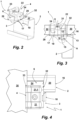
- the support of the intermediate element 6 on the base plate 8 of the connecting part as well as the gripping of the support section 17 by the stop leg 28 is shown in the perspective view of the fastening clamp 1 of the Figure 2 This shows the fastening clamp 1 in its fastening position, but without a photovoltaic module attached to the carrier 2 in this position.
- the abutment surface 14 is supported on the inside of the leg 16 of the support 2.
- the clamping axis of the fastening clamp 1 is located outside the support 2. This is unproblematic for clamping the fastening clamp 1, since the rigid properties of the photovoltaic module 30 or its frame prevent any otherwise possible adjustment of the fastening clamp 1 during clamping.
- the photovoltaic module 30 rests on the upper side of the intermediate element 6.
- upwardly projecting press-in claws 32 are formed in the section of the intermediate element 6 that comes into contact with the contact surface 20 of the support 2.
- the clamping element 4 rests with its lower support leg 34 formed on the shoulder 22 on the intermediate element 6, which in turn rests on the support surface 18 of the connecting part 3 and the contact surface 20 of the support 2.
- the width of the clamping element 4 is designed so that it extends from the contact surface 20 of the support 2 to over the support surface 18 of the support section 17 (see also Figure 2 ).
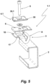
- FIG. 5 shows another fastening clamp 1.1, which is designed as a middle clamp.
- the fastening clamp 1.1 corresponds in terms of its structure to that of the fastening clamp 1 of the Figures 1 to 4 .
- the same parts are indicated with the same reference numerals for the fastening clamp 1.1 as for the fastening clamp 1. Since, with the exception of the clamping element 4.1, the other components are identical to those of the fastening clamp 1, only the differences in the clamping element 4.1 will be discussed below. Otherwise, the statements regarding the fastening clamp 1 apply equally to the fastening clamp 1.1.
- the fastening clamp 1 Since the fastening clamp 1 is designed as a middle clamp, its clamping element 4.1 does not have a support on the carrier 2 or the support section 17 of the connecting part 2.
- the clamping element 4.1 has two opposing clamping extensions 35, 35.1, the underside of which serves for the installation of a photovoltaic module 30.1, 30.2.
- the installation as an intermediate clamp of the fastening clamp 1.1 is shown in the top view of the Figure 7 visible. With a clamping extension 35 or 35.1, the clamping element 4.1 of the fastening clamp 1.1 engages over the edge of a respective photovoltaic module 30.1, 30.2. Tilting of the fastening clamp 1.1 when tensioning it to attach the photovoltaic modules 30.1, 30.2 to the support 2 is also effectively prevented in this embodiment by the rigid properties of the photovoltaic modules 30.1, 30.2.
Landscapes
- Engineering & Computer Science (AREA)
- General Engineering & Computer Science (AREA)
- Mechanical Engineering (AREA)
- Sustainable Development (AREA)
- Sustainable Energy (AREA)
- Thermal Sciences (AREA)
- Chemical & Material Sciences (AREA)
- Combustion & Propulsion (AREA)
- Physics & Mathematics (AREA)
- Life Sciences & Earth Sciences (AREA)
- Clamps And Clips (AREA)
- Connection Of Plates (AREA)
- Roof Covering Using Slabs Or Stiff Sheets (AREA)
Claims (14)
- Pince de fixation pour fixer un objet allongé et rigide, tel qu'un profilé de support, un panneau, tel qu'un module photovoltaïque, un composant de celui-ci ou similaire, à une sous-structure généralement constituée d'une pluralité de supports (2), comprenant :- un élément de serrage (4, 4.1) avec une extension de serrage (33 ; 35, 35.1) destinée à s'engager avec un objet (30 ; 30.1, 30.2) à fixer,- une pièce de liaison (3) avec un élément de liaison (A) pour soutenir la pince de fixation (1, 1.1) sur une butée du support (2) de la sous-structure, dans laquelle la butée pointe dans la direction opposée d'une surface de contact (20) fournie par le support de profilé (2) sur lequel l'objet à fixer doit être placé, lequel élément de liaison (A) présente une butée destinée à venir en prise sous le support (2) pour s'appuyer sur la butée du support (2) et la partie de liaison (3) présente une section de support (18) située à côté de l'extrémité latérale du support (2), qui, lorsque la pince de fixation (1, 1.1) est fixée au support (2), agit contre l'objet à fixer (30 ; 30.1, 30.2) et/ou une branche d'appui (34) de l'élément de serrage (4, 4.1), et- un dispositif de serrage (5, 7) pour serrer l'élément de serrage (4, 4.1) supporté sur un objet (30 ; 30.1, 30.2) à fixer par rapport à la pièce de liaison (3), de sorte qu'une force de serrage peut être appliquée à l'objet à fixer (30 ; 30.1, 30.2) via l'élément de serrage (4, 4.1), lequel dispositif de serrage dispose d'un moyen de serrage (5) dont l'axe de serrage (31) est guidé au-delà de l'extrémité latérale du support (2) lorsque la pince de fixation (1, 1.1) est fixée au support (2), dans laquelle la butée (14) du côté de la partie de connexion fait partie d'une partie de connexion en forme de crochet (3) destinée à venir en prise derrière un bord arrière du support (2) et l'extrémité libre d'un tel élément de liaison en forme de crochet (A) forme la butée pour l'appui sur le côté intérieur de la branche du support (2) qui fournit la surface de contact (20) avec son côté extérieur.
- Pince de fixation selon la revendication 1, caractérisée en ce que la surface d'appui (18) est située dans le même plan qu'une surface d'appui (20) prévue par le support (2) pour supporter l'objet (30 ; 30.1, 30.2) lorsque la pince de fixation (1, 1.1) est reliée à un support (2).
- Pince de fixation selon la revendication 1 ou 2, caractérisée en ce que la pièce de liaison (3) est une pièce estampée et pliée, dans laquelle l'élément de liaison (A) est constitué de deux branches (10, 10.1) pliées sur des côtés opposés par rapport à un corps de base (8), et les extrémités libres formant la butée venant en prise sous le support (2) sont reliées l'une à l'autre par une âme (13) formant une surface de butée (14).
- Pince de fixation selon la revendication 3, caractérisée en ce que la surface d'appui (18) est formée sur les composants restants de la pièce de liaison (3) avec l'interposition d'une manivelle (19), dans laquelle la hauteur de saut de la manivelle (19) est conçue de sorte que, lorsque la pince de fixation (1, 1.1) est reliée au support (2), la surface d'appui (18) se trouve dans le même plan que la surface de contact (20) du support (2).
- Pince de fixation selon l'une des revendications 1 à 4, caractérisée en ce que l'élément de serrage (4) pour utiliser la pince de fixation (1) comme pince latérale dispose d'une branche de support (34) qui s'appuie sur la surface d'appui (18) de la pièce de liaison (3) dans la position de serrage de la pince de fixation (1).
- Pince de fixation selon la revendication 5, caractérisée en ce que la branche de support (34) s'appuie en outre sur la surface de contact (20) du support (2) dans la position de serrage de la pince de fixation (1).
- Pince de fixation selon la revendication 5 ou 6, caractérisée en ce que la branche de support (34) peut prendre appui avec sa face frontale tournée vers la pièce de liaison (3) sur la surface d'appui (18) de la pièce de liaison (3).
- Pince de fixation selon l'une des revendications 5 à 7, caractérisée en ce que l'élément de serrage (4) présente un épaulement (22) décalé en direction de la pièce de liaison (3) par rapport à son extrémité supérieure entre son prolongement de serrage (33) et sa branche d'appui (34), épaulement sur lequel agit le moyen de serrage (5) lors du serrage de l'élément de serrage (4) par rapport à la pièce de liaison (3).
- Pince de fixation selon l'une des revendications 1 à 8, caractérisée en ce que le moyen de serrage est un boulon de serrage (5) avec une tête prenant appui sur l'élément de serrage (4) et avec une tige filetée qui s'engrène avec un passage de filetage intérieur (9) de la pièce de liaison (3).
- Pince de fixation selon l'une des revendications 1 à 9, caractérisée en ce que la pince de fixation (1, 1.1) dispose en outre d'un élément intermédiaire (6) inséré dans le dispositif de serrage entre l'objet à fixer (30 ; 30.1, 30.2) et la surface d'appui (18) de la pièce de liaison (3) et/ou la surface de contact (20) du profilé (2).
- Pince de fixation selon la revendication 10, caractérisée en ce que l'élément intermédiaire (6) est maintenu sur la pièce de liaison (3).
- Pince de fixation selon la revendication 11, caractérisée en ce que l'élément intermédiaire (6) est maintenu sur la pièce de liaison (3) par une liaison par clip, dans lequel l'élément intermédiaire (6) dispose de préférence des sections élastiques (27) nécessaires à la liaison par clip.
- Pince de fixation selon l'une des revendications 10 à 12, caractérisée en ce que l'élément intermédiaire (6) présente une extension plus grande dans le sens de son extension vers le support (2) que l'organe de liaison (A) de la pièce de liaison (3).
- Dispositif de fixation comprenant- un support (2) faisant partie d'une sous-structure,- un objet allongé et rigide (30 ; 30.1, 30.2) reposant sur le support (2) et- au moins une pince de fixation (1, 1.1) selon l'une des revendications 1 à 13,- laquelle pince de fixation (1, 1.1) est reliée à un support (2) de la sous-structure en venant en prise sous la branche (16) fournissant une surface de contact (20) du support (2) et en venant en prise derrière un bord arrière (15) du support (2), est supportée avec la butée (14) de son élément de liaison (A) sur le côté de la branche (16) du support (2) opposé à la surface de contact (20), et en outre l'objet à fixer (30 ; 30.1, 30.2) et/ou une branche de support (34) de la branche de serrage (4) de la pince de fixation (1) s'appuie sur la surface d'appui (18) de la pièce de liaison (3) qui est espacée de l'extrémité latérale de la branche (16) du support (2) portant la pince de fixation (1, 1.1).
Applications Claiming Priority (1)
| Application Number | Priority Date | Filing Date | Title |
|---|---|---|---|
| DE202023100439.3U DE202023100439U1 (de) | 2023-01-31 | 2023-01-31 | Befestigungsklemme |
Publications (3)
| Publication Number | Publication Date |
|---|---|
| EP4411150A1 EP4411150A1 (fr) | 2024-08-07 |
| EP4411150C0 EP4411150C0 (fr) | 2025-06-18 |
| EP4411150B1 true EP4411150B1 (fr) | 2025-06-18 |
Family
ID=89620695
Family Applications (1)
| Application Number | Title | Priority Date | Filing Date |
|---|---|---|---|
| EP24152282.0A Active EP4411150B1 (fr) | 2023-01-31 | 2024-01-17 | Pince de fixation |
Country Status (3)
| Country | Link |
|---|---|
| EP (1) | EP4411150B1 (fr) |
| DE (1) | DE202023100439U1 (fr) |
| ES (1) | ES3037246T3 (fr) |
Family Cites Families (6)
| Publication number | Priority date | Publication date | Assignee | Title |
|---|---|---|---|---|
| DE202011107843U1 (de) | 2011-11-10 | 2011-11-28 | Creotecc Gmbh | Endklemmen für gerahmte Photovoltaikmodule |
| DE202012005671U1 (de) * | 2012-06-12 | 2012-07-09 | Donauer Solartechnik Vertriebs Gmbh | Befestigungsvorrichtung für ein Solarmodul und Solarmodulanordnung mit der Befestigungsvorrichtung |
| DE202014009489U1 (de) | 2014-11-26 | 2014-12-12 | Mounting Systems Gmbh | Endhalter und Befestigungssystem zur Montage von Solarmodulen |
| DE102015013262B3 (de) | 2015-10-06 | 2017-01-12 | Lutz Wolff | Montagesystem für plattenförmige Körper, insbesondere Solarmodule |
| TWI716248B (zh) * | 2019-12-31 | 2021-01-11 | 景欣股份有限公司 | 勾卡式固定框架 |
| US20220216823A1 (en) * | 2021-01-06 | 2022-07-07 | Chen Lu Wang | Fixed structure of solar panels and c-shaped steel |
-
2023
- 2023-01-31 DE DE202023100439.3U patent/DE202023100439U1/de active Active
-
2024
- 2024-01-17 ES ES24152282T patent/ES3037246T3/es active Active
- 2024-01-17 EP EP24152282.0A patent/EP4411150B1/fr active Active
Also Published As
| Publication number | Publication date |
|---|---|
| EP4411150A1 (fr) | 2024-08-07 |
| ES3037246T3 (en) | 2025-09-30 |
| EP4411150C0 (fr) | 2025-06-18 |
| DE202023100439U1 (de) | 2024-05-02 |
Similar Documents
| Publication | Publication Date | Title |
|---|---|---|
| EP2434229B9 (fr) | Crochet de toit pour le montage de modules solaires sur des toits | |
| DE10344201A1 (de) | Solarmodulbefestigung, Verfahren zum Montieren einer Solaranlage und Anordnung aus einem Solarmodul und einem Solarmodulrahmen | |
| DE102009030799A1 (de) | Befestigungselement | |
| DE202007003060U1 (de) | Verbindungselement | |
| EP1647782A2 (fr) | Dispositif de support d'au moins un collecteur solaire | |
| EP2270403A1 (fr) | Rail de support | |
| DE19852298A1 (de) | Fassadenkonstruktion | |
| EP2253902B1 (fr) | Ensemble de composants pour le montage de modules solaires sur un toit | |
| EP2372269A2 (fr) | Dispositif de liaison et agencement de profilé | |
| AT406594B (de) | Montagesystem zur halterung von verkleidungselementen an bauwerken | |
| EP4411275B1 (fr) | Crochet de toit | |
| EP1717384B1 (fr) | Fixation pour accessoires de toit | |
| EP2430667A2 (fr) | Dispositif de support pour modules solaires | |
| EP4411150A1 (fr) | Pince de fixation | |
| AT500181B1 (de) | Tür- oder fensterbeschlag | |
| AT512429B1 (de) | Montageelement für einen spannrahmenteil eines spannrahmens und verfahren zur befestigung eines spannrahmenteiles eines spannrahmens mittels des montageelementes | |
| EP4411276A2 (fr) | Système de montage | |
| DE202004016002U1 (de) | Fassadenbefestigungssystem | |
| EP3176344B1 (fr) | Élément de faite ou d'arête de toit | |
| DE202012001078U1 (de) | Befestigungssystem für Solarmodule | |
| DE8814225U1 (de) | Höhenverstellbarer Lattenhalter für Dachstuhlkonstruktionen | |
| AT17359U1 (de) | Montagehalterung für ein Sandwichelement und System zur Befestigung einer Dachrinne an einem Sandwichelement | |
| DE4218098A1 (de) | Trag- und Befestigungseinrichtung | |
| WO1985001979A1 (fr) | Dispositif de fixation | |
| AT406174B (de) | Befestigungsteil für profile |
Legal Events
| Date | Code | Title | Description |
|---|---|---|---|
| PUAI | Public reference made under article 153(3) epc to a published international application that has entered the european phase |
Free format text: ORIGINAL CODE: 0009012 |
|
| STAA | Information on the status of an ep patent application or granted ep patent |
Free format text: STATUS: THE APPLICATION HAS BEEN PUBLISHED |
|
| STAA | Information on the status of an ep patent application or granted ep patent |
Free format text: STATUS: REQUEST FOR EXAMINATION WAS MADE |
|
| AK | Designated contracting states |
Kind code of ref document: A1 Designated state(s): AL AT BE BG CH CY CZ DE DK EE ES FI FR GB GR HR HU IE IS IT LI LT LU LV MC ME MK MT NL NO PL PT RO RS SE SI SK SM TR |
|
| 17P | Request for examination filed |
Effective date: 20240730 |
|
| P01 | Opt-out of the competence of the unified patent court (upc) registered |
Free format text: CASE NUMBER: APP_47038/2024 Effective date: 20240814 |
|
| GRAP | Despatch of communication of intention to grant a patent |
Free format text: ORIGINAL CODE: EPIDOSNIGR1 |
|
| STAA | Information on the status of an ep patent application or granted ep patent |
Free format text: STATUS: GRANT OF PATENT IS INTENDED |
|
| GRAS | Grant fee paid |
Free format text: ORIGINAL CODE: EPIDOSNIGR3 |
|
| RIC1 | Information provided on ipc code assigned before grant |
Ipc: F16B 5/06 20060101AFI20250404BHEP |
|
| GRAA | (expected) grant |
Free format text: ORIGINAL CODE: 0009210 |
|
| STAA | Information on the status of an ep patent application or granted ep patent |
Free format text: STATUS: THE PATENT HAS BEEN GRANTED |
|
| INTG | Intention to grant announced |
Effective date: 20250416 |
|
| AK | Designated contracting states |
Kind code of ref document: B1 Designated state(s): AL AT BE BG CH CY CZ DE DK EE ES FI FR GB GR HR HU IE IS IT LI LT LU LV MC ME MK MT NL NO PL PT RO RS SE SI SK SM TR |
|
| REG | Reference to a national code |
Ref country code: GB Ref legal event code: FG4D Free format text: NOT ENGLISH |
|
| REG | Reference to a national code |
Ref country code: CH Ref legal event code: EP |
|
| REG | Reference to a national code |
Ref country code: DE Ref legal event code: R096 Ref document number: 502024000065 Country of ref document: DE |
|
| REG | Reference to a national code |
Ref country code: CH Ref legal event code: EP |
|
| REG | Reference to a national code |
Ref country code: IE Ref legal event code: FG4D Free format text: LANGUAGE OF EP DOCUMENT: GERMAN |
|
| U01 | Request for unitary effect filed |
Effective date: 20250702 |
|
| U07 | Unitary effect registered |
Designated state(s): AT BE BG DE DK EE FI FR IT LT LU LV MT NL PT RO SE SI Effective date: 20250710 |
|
| REG | Reference to a national code |
Ref country code: ES Ref legal event code: FG2A Ref document number: 3037246 Country of ref document: ES Kind code of ref document: T3 Effective date: 20250930 |
|
| PG25 | Lapsed in a contracting state [announced via postgrant information from national office to epo] |
Ref country code: NO Free format text: LAPSE BECAUSE OF FAILURE TO SUBMIT A TRANSLATION OF THE DESCRIPTION OR TO PAY THE FEE WITHIN THE PRESCRIBED TIME-LIMIT Effective date: 20250918 Ref country code: GR Free format text: LAPSE BECAUSE OF FAILURE TO SUBMIT A TRANSLATION OF THE DESCRIPTION OR TO PAY THE FEE WITHIN THE PRESCRIBED TIME-LIMIT Effective date: 20250919 |
|
| PG25 | Lapsed in a contracting state [announced via postgrant information from national office to epo] |
Ref country code: HR Free format text: LAPSE BECAUSE OF FAILURE TO SUBMIT A TRANSLATION OF THE DESCRIPTION OR TO PAY THE FEE WITHIN THE PRESCRIBED TIME-LIMIT Effective date: 20250618 |
|
| PG25 | Lapsed in a contracting state [announced via postgrant information from national office to epo] |
Ref country code: RS Free format text: LAPSE BECAUSE OF FAILURE TO SUBMIT A TRANSLATION OF THE DESCRIPTION OR TO PAY THE FEE WITHIN THE PRESCRIBED TIME-LIMIT Effective date: 20250918 |
|
| PG25 | Lapsed in a contracting state [announced via postgrant information from national office to epo] |
Ref country code: IS Free format text: LAPSE BECAUSE OF FAILURE TO SUBMIT A TRANSLATION OF THE DESCRIPTION OR TO PAY THE FEE WITHIN THE PRESCRIBED TIME-LIMIT Effective date: 20251018 |
|
| PG25 | Lapsed in a contracting state [announced via postgrant information from national office to epo] |
Ref country code: SM Free format text: LAPSE BECAUSE OF FAILURE TO SUBMIT A TRANSLATION OF THE DESCRIPTION OR TO PAY THE FEE WITHIN THE PRESCRIBED TIME-LIMIT Effective date: 20250618 |
|
| PG25 | Lapsed in a contracting state [announced via postgrant information from national office to epo] |
Ref country code: CZ Free format text: LAPSE BECAUSE OF FAILURE TO SUBMIT A TRANSLATION OF THE DESCRIPTION OR TO PAY THE FEE WITHIN THE PRESCRIBED TIME-LIMIT Effective date: 20250618 |
|
| PG25 | Lapsed in a contracting state [announced via postgrant information from national office to epo] |
Ref country code: PL Free format text: LAPSE BECAUSE OF FAILURE TO SUBMIT A TRANSLATION OF THE DESCRIPTION OR TO PAY THE FEE WITHIN THE PRESCRIBED TIME-LIMIT Effective date: 20250618 |
|
| PG25 | Lapsed in a contracting state [announced via postgrant information from national office to epo] |
Ref country code: SK Free format text: LAPSE BECAUSE OF FAILURE TO SUBMIT A TRANSLATION OF THE DESCRIPTION OR TO PAY THE FEE WITHIN THE PRESCRIBED TIME-LIMIT Effective date: 20250618 |
|
| U20 | Renewal fee for the european patent with unitary effect paid |
Year of fee payment: 3 Effective date: 20251219 |
|
| PGFP | Annual fee paid to national office [announced via postgrant information from national office to epo] |
Ref country code: ES Payment date: 20260217 Year of fee payment: 3 |
|
| PLBE | No opposition filed within time limit |
Free format text: ORIGINAL CODE: 0009261 |
|
| STAA | Information on the status of an ep patent application or granted ep patent |
Free format text: STATUS: NO OPPOSITION FILED WITHIN TIME LIMIT |
|
| REG | Reference to a national code |
Ref country code: CH Ref legal event code: L10 Free format text: ST27 STATUS EVENT CODE: U-0-0-L10-L00 (AS PROVIDED BY THE NATIONAL OFFICE) Effective date: 20260430 |