EP4411152A1 - Ferrure pour un composant - Google Patents
Ferrure pour un composant Download PDFInfo
- Publication number
- EP4411152A1 EP4411152A1 EP23154583.1A EP23154583A EP4411152A1 EP 4411152 A1 EP4411152 A1 EP 4411152A1 EP 23154583 A EP23154583 A EP 23154583A EP 4411152 A1 EP4411152 A1 EP 4411152A1
- Authority
- EP
- European Patent Office
- Prior art keywords
- plate
- opening
- component
- fitting according
- threaded bolt
- Prior art date
- Legal status (The legal status is an assumption and is not a legal conclusion. Google has not performed a legal analysis and makes no representation as to the accuracy of the status listed.)
- Pending
Links
Images


Classifications
-
- F—MECHANICAL ENGINEERING; LIGHTING; HEATING; WEAPONS; BLASTING
- F16—ENGINEERING ELEMENTS AND UNITS; GENERAL MEASURES FOR PRODUCING AND MAINTAINING EFFECTIVE FUNCTIONING OF MACHINES OR INSTALLATIONS; THERMAL INSULATION IN GENERAL
- F16B—DEVICES FOR FASTENING OR SECURING CONSTRUCTIONAL ELEMENTS OR MACHINE PARTS TOGETHER, e.g. NAILS, BOLTS, CIRCLIPS, CLAMPS, CLIPS OR WEDGES; JOINTS OR JOINTING
- F16B9/00—Connections of rods or tubular parts to flat surfaces at an angle
- F16B9/05—Connections of rods or tubular parts to flat surfaces at an angle by way of an intermediate member
- F16B9/054—Connections of rods or tubular parts to flat surfaces at an angle by way of an intermediate member the intermediate member being threaded
-
- F—MECHANICAL ENGINEERING; LIGHTING; HEATING; WEAPONS; BLASTING
- F16—ENGINEERING ELEMENTS AND UNITS; GENERAL MEASURES FOR PRODUCING AND MAINTAINING EFFECTIVE FUNCTIONING OF MACHINES OR INSTALLATIONS; THERMAL INSULATION IN GENERAL
- F16B—DEVICES FOR FASTENING OR SECURING CONSTRUCTIONAL ELEMENTS OR MACHINE PARTS TOGETHER, e.g. NAILS, BOLTS, CIRCLIPS, CLAMPS, CLIPS OR WEDGES; JOINTS OR JOINTING
- F16B37/00—Nuts or like thread-engaging members
- F16B37/08—Quickly-detachable or mountable nuts, e.g. consisting of two or more parts; Nuts movable along the bolt after tilting the nut
- F16B37/0807—Nuts engaged from the end of the bolt, e.g. axially slidable nuts
- F16B37/0842—Nuts engaged from the end of the bolt, e.g. axially slidable nuts fastened to the threaded bolt with snap-on-action, e.g. push-on nuts for stud bolts
-
- F—MECHANICAL ENGINEERING; LIGHTING; HEATING; WEAPONS; BLASTING
- F16—ENGINEERING ELEMENTS AND UNITS; GENERAL MEASURES FOR PRODUCING AND MAINTAINING EFFECTIVE FUNCTIONING OF MACHINES OR INSTALLATIONS; THERMAL INSULATION IN GENERAL
- F16B—DEVICES FOR FASTENING OR SECURING CONSTRUCTIONAL ELEMENTS OR MACHINE PARTS TOGETHER, e.g. NAILS, BOLTS, CIRCLIPS, CLAMPS, CLIPS OR WEDGES; JOINTS OR JOINTING
- F16B37/00—Nuts or like thread-engaging members
- F16B37/08—Quickly-detachable or mountable nuts, e.g. consisting of two or more parts; Nuts movable along the bolt after tilting the nut
- F16B37/0807—Nuts engaged from the end of the bolt, e.g. axially slidable nuts
- F16B37/0857—Nuts engaged from the end of the bolt, e.g. axially slidable nuts with the threaded portions of the nut engaging the thread of the bolt by the action of one or more springs or resilient retaining members
Definitions
- the present invention relates to a fitting for a component, in particular a wooden component. Furthermore, the present invention relates to a system which comprises the fitting and the component.
- Such a fitting can be used both to support a component on the ground or on a supporting structure and to connect a component to another component such as a beam, a post, a wall or the like.
- a variety of different fittings are known in the state of the art for these various applications.
- the document EP 3 009 583 A1 a fitting that can be used as a support foot for a post with a plate that can be mounted on the underside of the post with a threaded sleeve into which a threaded bolt that can be supported on the ground is screwed in at an adjustable height. Mounting this fitting on the post is laborious and time-consuming, which makes it difficult to set up the post quickly.
- the already mounted fitting and the post can easily twist against each other, which is why the post can only be aligned imprecisely and temporarily.
- the invention aims to provide an improved fitting which can be quickly mounted on the component and enables precise alignment and stable anchoring of the fitting on the component.
- the fitting according to the invention can be mounted on the component particularly quickly.
- the first or second plate is first anchored to the component; then the threaded bolt is guided through the aligned openings of the two plates as far as necessary in a linear relative movement between the threaded bolt and the component, with its threads ratcheting ride over the ends of the spring tongues and finally lock into place; and then the nut is tightened against the second plate in order to clamp the spring tongues locked onto the threaded bolt against the threaded bolt on the one hand and the two plates against each other on the other.
- the plates could of course also be clamped first - separately from the component - by tightening the nut on the threaded bolt, and only then anchor one of the plates to the component.
- the threaded bolt In the clamped position, the threaded bolt is securely locked at the free ends of the spring tongues. This means that the threaded bolt cannot be pulled out, as a tensile force via the spring tongues and their acute angles causes a radial force outwards on the first plate, which absorbs the first plate and thus resists the radial force. In addition, the threaded bolt cannot be twisted, as the clamped spring tongues and thus the first plate absorb a torque acting on the threaded bolt.
- the fitting Before tightening the nut, the fitting can be precisely aligned with the component and is only locked in its aligned position when the nut is tightened. If the fitting is to be connected to another component, for example, the two components can be precisely aligned with each other and then permanently connected.
- the fitting according to the invention enables reversible assembly on the component. If necessary, the clamped position can be changed simply by loosening the nut and the threaded bolt can be turned relative to the first plate and thus unscrewed from the spring tongues.
- the first plate, only the second plate or both plates can be anchored to the component, e.g. glued, welded, flanged, nailed, etc., or engage with it with a positive fit.
- the second plate has two or more fastening holes distributed around the second opening. This allows the second plate to be screwed to the component quickly and easily using screws that pass through the fastening holes.
- the first plate has two or more fastening holes distributed around the first opening to anchor it so that it can be screwed to the component.
- both plates can also have fastening holes.
- the fastening holes of the first and second plates are aligned in the installation position. This means that the first plate and the second plate can be anchored particularly securely to the component using screws that pass through the fastening holes.
- each spring tongue has a two- or multi-start thread section corresponding to the threaded bolt.
- the two- or multi-start thread sections corresponding to the threaded bolt ensure particularly good force transmission from the threaded bolt to the spring tongues. As a result, a particularly high force can be applied to transferred to the part of the first plate surrounding the first opening and reliably received by it.
- the acute angle mentioned is between 5° and 60°, preferably between 10° and 30°, relative to the plane of the first plate. This makes it particularly easy for the threaded bolt to be brought into its locked position in one direction and to be locked therein particularly securely against twisting or slipping.
- the first plate can have two or more spring tongues, which can be distributed as desired around the circumference of the first opening.
- the first plate has three or four spring tongues, which are evenly distributed around the circumference of the first opening.
- Such a number and arrangement of spring tongues is easy to produce and enables a particularly even distribution of force from the threaded bolt to the first plate and vice versa.
- first plate and the second plate are essentially congruent in the contact position.
- the plate congruence also allows a recess to be provided in the component that corresponds to the plate shape, so that both plates can be easily accommodated in the recess.
- first and second plates are circular, square or regularly polygonal in their respective plate planes in order to provide several rotationally symmetrical fitting positions for the congruent plates. so that they can be mounted as error-tolerantly as possible and can be quickly and easily aligned in the installation position.
- the two plates can be made of any material, e.g. metal, plastic, especially fiber-reinforced plastic, wood, etc.
- the first plate is made of metal, preferably spring steel.
- the first plate is then particularly strong and can optionally be made in one piece with its spring tongues.
- the second plate is made of metal, preferably steel, in order to achieve high strength.
- the second plate can be perforated several times to reduce the weight. Or, with the same total weight, the second plate can be made thicker in the non-perforated areas to improve its stability.
- the fitting can further comprise a washer that can be arranged between the nut and the second plate.
- the washer can be used to distribute the contact force of the tightened nut over the second plate, thus achieving a particularly strong tension between the first and second plates on the one hand and the threaded bolt and the first plate on the other.
- the fitting can comprise a mounting element which can be arranged between the first plate and the second plate or on the said one side of the first plate.
- Plate made of elastic material, which has a third opening passing through it, which in the contact position is aligned with the first and second openings.
- Such a plate can elastically brace the elements resting on it against each other in order to dampen peak loads and compensate for manufacturing tolerances.
- the elements resting on it can be electrically, thermally and/or fluid-tightly insulated from each other, e.g. to prevent liquid from entering a wooden component via the fitting.
- the invention provides a system that comprises a fitting as described herein and a component, in particular a wooden component.
- the component preferably has a recess for receiving the spring tongues and the end of the threaded bolt that passes through the aligned openings. This allows the spring tongues and the end of the threaded bolt to be accommodated in the component in a space-saving manner and thus also protected from the weather.
- the recess has an inner shoulder for supporting the peripheral area of the one side of the first plate that lies around the spring tongues.
- the first plate of the fitting can be precisely aligned with the component on the inner shoulder and, if necessary, anchored particularly securely to the component by resting against the inner shoulder.
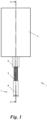
- a fitting 1 which can be anchored to a component (here: to a post) 2.
- the fitting 1 comprises a first and a second plate 3, 4, at least one of which can be firmly anchored to the component 2, a threaded bolt 5 and a nut 6 which can be screwed onto the threaded bolt 5.
- the fitting 1 can be anchored to a wide variety of components 2 for many purposes.
- the fitting 1 acts as a "support foot" to support the component 2 at a lower end 7 of the threaded bolt 5, e.g. on the ground or on a supporting structure.
- the lower end 7 can be concreted into the ground, held in a dowel 8, in a threaded bushing of a step or a threshold, etc., or designed as a plate.
- the fitting 1 functions as a "connector” to connect one component 2 to another component 2 (not shown) via the threaded bolt 5, e.g. via its lower end 7.
- the component(s) 2 can have any shape and be made of any material, in particular wood, or metal, concrete, plastic, composite material, brick, etc.
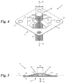
- the first plate 3 has a first opening 9 - in particular in the middle - which passes through the first plate 3 from its top side 10 to its bottom side 11.
- the first plate 3 has at least two spring tongues 13 distributed over the circumference 12 of the first opening 9 (here: four spring tongues 13 evenly distributed over the circumference 12).
- the spring tongues 13 each protrude radially into the first opening 9 and at the same time at the top side 10 of the first plate 3 at an acute angle ⁇ from the plate plane ⁇ , more precisely from the peripheral area 14 of the first plate 3 around the spring tongues 13.
- the first opening 9 does not have to be circular (as in the example shown); the aforementioned radial orientations of the spring tongues 13 in any case indicate (radial) directions of the respective spring tongues 13 from their root on the circumference 12 of the first opening 9 into the interior of the first opening 9.
- each spring tongue 13 facing away from the circumference 12 of the first opening 9 is free.
- a clear width W remains between the free ends 15 of the spring tongues 13.
- the threaded bolt 5 has a diameter D, i.e. an external or nominal thread diameter that exceeds the clear width W remaining between the free ends 15 of the spring tongues 13.
- the second plate has 4, as in Fig.8 shown, a - in particular central - second opening 16 which passes through the second plate 4 from its upper side 17 to its lower side 18.
- the first and second openings 9, 16 are aligned so that the threaded bolt 5 can be guided with its upper end 19 through the openings 9, 16.
- the second opening 16 can either accommodate the threaded bolt 5 with play or, alternatively, have an internal thread (not shown) so that the threaded bolt 5 can be guided through by screwing it in.
- the spring tongues 13 are each displaced upwards at their free ends 15 by the thread 20 of the threaded bolt 5 and forced outwards by the acute angles ⁇ being temporarily increased slightly against the spring effect, in order to then engage again in the next thread of the threaded bolt 5.
- the threaded bolt 5 is, however, latched or locked, since it cannot reduce the acute angle ⁇ of the spring tongues 13 with respect to the plate plane ⁇ : to do so, it would have to force open the peripheral area 14 of the first plate 3 remaining around the first opening 9 via the spring tongues 13, which can be prevented by a suitable design of the first plate 3.
- the nut 6 can be tightened against the underside 18 of the second plate 4 facing away from the first plate 3.
- the threaded bolt 5 is spread or braced against the free ends 15 of the spring tongues 13 in the other normal direction A 2 by the locking effect just described and on the other hand the second plate 4 is pressed against the first plate 3.
- the fitting 1 is in a braced position. Position which can be left again by loosening the nut 6, e.g. to anchor the fitting to another component 2.
- a washer 6' ( Fig.2 and 3 ) between the nut 6 and the second plate 4.
- the anchoring of one of the plates 3 or 4 or both plates 3 and 4 to the component 2 can be carried out in many different ways, be it by force, form or material connection and - depending on the application - either before the threaded bolt 5 is passed through or after.
- the first and second plates 3, 4 can each have two or more (here: four) fastening holes 21, 22 distributed around the respective opening 9, 16, which are aligned in the contact position of the plates 3, 4, e.g. for fastening screws 23 for screwing to the component 2.
- only the second plate 4 could have fastening holes 22, e.g. in an area of the second plate 4 that protrudes beyond the first plate 3 in the contact position of the plates 3, 4 (not shown).
- only the first plate 3 could have fastening holes 21 and the second plate 4 could then be held, e.g. only by the contact pressure of the nut 6.
- the free ends 15 of the spring tongues 13 can only engage in a single thread of the thread 20 ( Fig. 2 , 4 and 5 ) or, alternatively, in several threads simultaneously.
- the Fig. 6 and 7 an optional Variant in which the free end 15 of each spring tongue 13 has a two- or multi-start threaded section 24 corresponding to the threaded bolt 5, so that the thread 20 of the threaded bolt 5 can engage in the threaded sections 24 of the free ends 15 of the spring tongues 13.
- the first plate 3 could have, for example, only two or three or five or more spring tongues 13 instead of the four shown, which can, for example, be formed in one piece with the plate 3 or welded, glued, clamped, etc. to it.
- the spring tongues 13 can be evenly distributed over the circumference of the first opening 9 as shown, so that in plan view all angles between two adjacent spring tongues 13 are always the same, or they can be unevenly distributed.
- a single spring tongue 13 could protrude radially from one circumferential side of the first opening 9 and two further spring tongues 13 closely adjacent to one another could protrude radially from the opposite other circumferential side of the first opening 9; in plan view this optionally results in mirror symmetry.
- the acute angle ⁇ is approximately 15° relative to the plate plane ⁇ in the first opening 9.
- the acute angle ⁇ is between 5° and 60°, but will usually be between 10° and 30°.
- the acute angle ⁇ can be in the relaxed state of the spring tongues 13, ie without the threaded bolt 5 locked between the free ends 13 ( Fig.5 and 7 ), another value than in the case where the threaded bolt 3 assumes its locked position ( Fig. 2 , 4 and 6 ).
- the two plates 3, 4 can have any shape.
- the two plates 3, 4 are essentially square in their respective plate planes and of equal size, so that they can lie congruently against each other in four rotationally symmetrical positions in the contact position ( Fig. 2 ).
- the two plates 3, 4 could be circular or regularly polygonal, for example.
- the plates 3, 4 can have asymmetrical shapes and/or not be made to overlap.
- the two plates 3, 4 can be made of any material, e.g. metal, plastic, in particular fiber-reinforced plastic, wood or another material.
- the first plate 3 and the second plate 4 can be made of different materials.
- the first plate 3 can be made of spring steel and/or the second plate 4 can be made of metal, in particular steel.
- the second plate 4 can optionally have several openings 25 for weight reduction.
- the openings 25 can, for example, be arranged at positions of low mechanical stress, e.g. between the fastening holes 22 of the second plate 4.
- the shape of the component 2 can optionally be adapted to that of the fitting 1.
- the component 2 has a recess 26 for receiving the spring tongues 13 and the upper end 19 of the threaded bolt 5 when the latter is guided through the aligned openings 9, 16.
- the recess 26 also has an inner shoulder 27 against which the peripheral region 14 of the upper side of the first plate 3, which lies around the spring tongues 13, can rest. Due to its shape corresponding to the shape of the first plate 3, the inner shoulder 27 aligns the first plate 3 and thus the fitting 1 on the component 2.
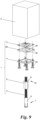
- the fitting 1 can optionally have an elastic plate 28, which has a third opening 29 passing through it for the passage of the bolt 5, which is aligned with the first and second openings 9, 16 in the contact position.
- the elastic plate 28 can be arranged between the first plate 3 and the second plate 4 ( Fig.9 ) and/or between the first plate 3 and the component 2, i.e. on the top side 11 of the first plate 3 (not shown), in order to elastically brace the elements resting thereon against each other and/or to insulate them from each other electrically, thermally and/or fluid-tight.
- the elastic plate 28 can be made from a variety of elastic materials, e.g. from natural and/or synthetic rubber, in particular from an elastomer.
- the elastic plate 28 can extend over a small area around the third opening 29 and leave the fastening holes 21, 22, if present, free (not shown) or can extend over the fastening holes 21, 22. In the latter case, the elastic plate 28 can either have openings 30 for the passage of the fastening screws 23 or cover the fastening holes 21, 22 so that the fastening screws 23 cut through the elastic plate 28 when screwed in. It is understood that the directions “top” (top side, upper end) and “bottom” (bottom side, lower end) have been used here only for reasons of clarity, but do not necessarily have to correspond to a direction of gravitational acceleration.
Landscapes
- Engineering & Computer Science (AREA)
- General Engineering & Computer Science (AREA)
- Mechanical Engineering (AREA)
- Joining Of Building Structures In Genera (AREA)
Priority Applications (1)
| Application Number | Priority Date | Filing Date | Title |
|---|---|---|---|
| EP23154583.1A EP4411152A1 (fr) | 2023-02-02 | 2023-02-02 | Ferrure pour un composant |
Applications Claiming Priority (1)
| Application Number | Priority Date | Filing Date | Title |
|---|---|---|---|
| EP23154583.1A EP4411152A1 (fr) | 2023-02-02 | 2023-02-02 | Ferrure pour un composant |
Publications (1)
| Publication Number | Publication Date |
|---|---|
| EP4411152A1 true EP4411152A1 (fr) | 2024-08-07 |
Family
ID=85172585
Family Applications (1)
| Application Number | Title | Priority Date | Filing Date |
|---|---|---|---|
| EP23154583.1A Pending EP4411152A1 (fr) | 2023-02-02 | 2023-02-02 | Ferrure pour un composant |
Country Status (1)
| Country | Link |
|---|---|
| EP (1) | EP4411152A1 (fr) |
Citations (5)
| Publication number | Priority date | Publication date | Assignee | Title |
|---|---|---|---|---|
| US2378957A (en) * | 1942-06-29 | 1945-06-26 | Tinnerman Products Inc | Fastening device |
| US3263630A (en) * | 1964-04-24 | 1966-08-02 | John I Foster Jr | Furniture fasteners |
| US3443530A (en) * | 1967-07-06 | 1969-05-13 | Raymond T Carlson | Furniture fastener |
| DE29710749U1 (de) * | 1997-06-19 | 1998-10-15 | Springfix-Befestigungstechnik GmbH, 73084 Salach | Befestigungsklammer zum Einstecken in ein dünnwandiges Bauteil |
| EP3009583A1 (fr) | 2014-10-15 | 2016-04-20 | VH Holding GmbH | Pied de colonne |
-
2023
- 2023-02-02 EP EP23154583.1A patent/EP4411152A1/fr active Pending
Patent Citations (5)
| Publication number | Priority date | Publication date | Assignee | Title |
|---|---|---|---|---|
| US2378957A (en) * | 1942-06-29 | 1945-06-26 | Tinnerman Products Inc | Fastening device |
| US3263630A (en) * | 1964-04-24 | 1966-08-02 | John I Foster Jr | Furniture fasteners |
| US3443530A (en) * | 1967-07-06 | 1969-05-13 | Raymond T Carlson | Furniture fastener |
| DE29710749U1 (de) * | 1997-06-19 | 1998-10-15 | Springfix-Befestigungstechnik GmbH, 73084 Salach | Befestigungsklammer zum Einstecken in ein dünnwandiges Bauteil |
| EP3009583A1 (fr) | 2014-10-15 | 2016-04-20 | VH Holding GmbH | Pied de colonne |
Similar Documents
| Publication | Publication Date | Title |
|---|---|---|
| DE202014002813U1 (de) | Temporäre Wandstütze | |
| AT16386U2 (de) | Vorrichtung zur Sicherung von Personen gegen Absturz | |
| DE102021210759A1 (de) | Schutzzaunsystem und Verfahren zum Montieren eines Schutzzaunsystems | |
| WO2001098597A1 (fr) | Systeme de liaison destine a la fixation rigide d'au moins deux elements | |
| WO2010000403A2 (fr) | Stabilisateur à dispositif d'ajustage pour des ancrages au sol | |
| EP4411152A1 (fr) | Ferrure pour un composant | |
| EP3586614B1 (fr) | Systeme de connection pour meuble modulaire ou stand de foire | |
| EP1247922B1 (fr) | Support de sol avec une plaque de tête pour supporter une structure de faux plancher surélevé et structure de faux plancher surélevé | |
| WO2012041606A1 (fr) | Dispositif de fixation à un bâtiment | |
| EP3211146B1 (fr) | Systeme de liaison pour une construction en bois | |
| DE2606940A1 (de) | Befestigungsmittel | |
| DE19843293C2 (de) | An einer Stirnseite eines Holzständers befestigter Stützfuß | |
| DE102014004160B3 (de) | Einrichtung zum Spannen von Strangelementen | |
| EP4314428A1 (fr) | Ensemble de liaison pour relier deux composants dans le domaine de la construction | |
| DE29820923U1 (de) | Befestigungselement | |
| DE102017206376B4 (de) | Stützenfuß | |
| DE102020134623B4 (de) | Befestigungsanordnung zur Bodenbefestigung | |
| EP4299930B1 (fr) | Dispositif de liaison pour deux composants | |
| DE102009057389A1 (de) | Schraube | |
| EP0866231B1 (fr) | Dispositif de fixation préfabriqué | |
| DE102010049194A1 (de) | Justiersystem für Bauelemente | |
| AT522359B1 (de) | Verbindungsvorrichtung zum kraftschlüssigen Verbinden wenigstens zweier Betonfertigteile | |
| EP0704011A1 (fr) | Systeme et element de liaison de pieces en bois | |
| AT520550B1 (de) | Adaptervorrichtung für einen Rammpfahl | |
| DE29810981U1 (de) | Befestigungseinheit zur Befestigung eines Bauelements, insbesondere Rohr o.dgl. Gegenstand |
Legal Events
| Date | Code | Title | Description |
|---|---|---|---|
| PUAI | Public reference made under article 153(3) epc to a published international application that has entered the european phase |
Free format text: ORIGINAL CODE: 0009012 |
|
| STAA | Information on the status of an ep patent application or granted ep patent |
Free format text: STATUS: THE APPLICATION HAS BEEN PUBLISHED |
|
| AK | Designated contracting states |
Kind code of ref document: A1 Designated state(s): AL AT BE BG CH CY CZ DE DK EE ES FI FR GB GR HR HU IE IS IT LI LT LU LV MC ME MK MT NL NO PL PT RO RS SE SI SK SM TR |
|
| STAA | Information on the status of an ep patent application or granted ep patent |
Free format text: STATUS: REQUEST FOR EXAMINATION WAS MADE |
|
| 17P | Request for examination filed |
Effective date: 20250206 |