EP4411191A1 - Joint à rotule - Google Patents
Joint à rotule Download PDFInfo
- Publication number
- EP4411191A1 EP4411191A1 EP23382096.8A EP23382096A EP4411191A1 EP 4411191 A1 EP4411191 A1 EP 4411191A1 EP 23382096 A EP23382096 A EP 23382096A EP 4411191 A1 EP4411191 A1 EP 4411191A1
- Authority
- EP
- European Patent Office
- Prior art keywords
- ball joint
- shroud
- bellow
- outer shroud
- housing
- Prior art date
- Legal status (The legal status is an assumption and is not a legal conclusion. Google has not performed a legal analysis and makes no representation as to the accuracy of the status listed.)
- Pending
Links
Images



Classifications
-
- F—MECHANICAL ENGINEERING; LIGHTING; HEATING; WEAPONS; BLASTING
- F01—MACHINES OR ENGINES IN GENERAL; ENGINE PLANTS IN GENERAL; STEAM ENGINES
- F01D—NON-POSITIVE DISPLACEMENT MACHINES OR ENGINES, e.g. STEAM TURBINES
- F01D25/00—Component parts, details, or accessories, not provided for in, or of interest apart from, other groups
- F01D25/24—Casings; Casing parts, e.g. diaphragms, casing fastenings
-
- F—MECHANICAL ENGINEERING; LIGHTING; HEATING; WEAPONS; BLASTING
- F16—ENGINEERING ELEMENTS AND UNITS; GENERAL MEASURES FOR PRODUCING AND MAINTAINING EFFECTIVE FUNCTIONING OF MACHINES OR INSTALLATIONS; THERMAL INSULATION IN GENERAL
- F16L—PIPES; JOINTS OR FITTINGS FOR PIPES; SUPPORTS FOR PIPES, CABLES OR PROTECTIVE TUBING; MEANS FOR THERMAL INSULATION IN GENERAL
- F16L27/00—Adjustable joints; Joints allowing movement
- F16L27/02—Universal joints, i.e. with mechanical connection allowing angular movement or adjustment of the axes of the parts in any direction
- F16L27/04—Universal joints, i.e. with mechanical connection allowing angular movement or adjustment of the axes of the parts in any direction with partly-spherical engaging surfaces
-
- F—MECHANICAL ENGINEERING; LIGHTING; HEATING; WEAPONS; BLASTING
- F02—COMBUSTION ENGINES; HOT-GAS OR COMBUSTION-PRODUCT ENGINE PLANTS
- F02C—GAS-TURBINE PLANTS; AIR INTAKES FOR JET-PROPULSION PLANTS; CONTROLLING FUEL SUPPLY IN AIR-BREATHING JET-PROPULSION PLANTS
- F02C7/00—Features, components parts, details or accessories, not provided for in, or of interest apart form groups F02C1/00 - F02C6/00; Air intakes for jet-propulsion plants
Definitions
- the present invention relates to a ball joint for connecting together two tubular portions of a duct assembly in a gas turbine engine and allows angular movement between these two tubular portions. More particularly, the invention relates to an improved configuration of ball joint provided with local thickening that significantly improves the mechanical properties of the ball joint.
- Turbine engines and particularly gas or combustion turbine engines, are rotary engines that extract energy from a flow of combusted gases passing through the engine in a series of compressor stages, which include pairs of rotating blades and stationary vanes, through a combustor, and then onto a multitude of turbine stages, also including multiple pairs of rotating blades and stationary vanes.
- Duct assemblies are provided about the turbine engine and provide conduits for the flow of various operating fluids to and from the turbine engine.
- one of the operating fluids in the turbine engine is bleed air.
- Current systems use ball joints or axial joints in the duct to meet requirements for flexibility, which compromise system dynamic performance by increasing the weight of the system.
- ball joints are used for joining together pressurized fluid carrying conduits which requires articulation there between.
- An integral bellows seal is provided inside the ball joints for preventing leakage of fluid flow there through while allowing articulation of the ball joint itself.
- the current configuration of ball joints has a structure composed with components manufactured by forming whose materials are compatible with forming process. This has the disadvantage of limiting the materials that can be used and has an impact on bending moment due to the intrinsic tolerances of the forming processes.
- the current ball joint components have a quasi-constant thickness which leads to an increase in weight due to non-optimized thicknesses.
- these known ball joints needs large thicknesses to support the loads and maintenance of the ball joint structure itself and also needs stress concentrators.
- the present invention provides a ball joint with an improved configuration of local thickening that avoids, among other things, the above drawbacks that the current ball joints presents.
- the present invention provides a ball joint according to claim 1 and a duct assembly according to claim 14.
- preferred embodiments of the invention are defined.
- a first aspect of the invention provides a ball joint for duct assembly of a gas turbine engine.
- Ball joints are used in fluid lines to impart limited flexibility for the purpose of accommodating tolerances, thermal expansion and vehicular motion.
- the present ball joint is intended for joining two tubular portions of a duct assembly of a gas turbine engine, however, this ball joint can be used in almost any type of fluid line.
- the present ball joint is configured for joining a first tubular portion with a second tubular portion, both tubular portions of the duct assembly.
- Each tubular portions of the duct assembly has a longitudinal axis.
- the ball joint comprising:
- the present ball joint is provided to support the articulation between the two tubular portions of the duct assembly through the housing and the flexure capability of the bellow.
- the ball joint primarily allows the bellow to flex while holding the tubular portions of the duct assembly together, without axial deformation.
- the housing prevents the axial movement of the two tubular portions.
- the tubular portions of the duct assembly rotate in solidarity with the respective shrouds of the housing to which they are attached. Therefore, when the tubular portions of the duct assembly are pressurized, the ball joint allows the bellow to flex within predetermined angle limits beyond which the ball joint would be broken in that the shrouds of the housing would be uncoupled and the bellow would stretch freely.
- the flexure capability of the bellow is limited to accommodate variations in the angles which the longitudinal axes of the tubular portions form with respect to one another.
- the bellow serves to permit relative flexure within a limited angular range between the tubular portions of the duct assembly while maintaining the water tightness inside the duct.
- the present ball joint allows only turns with respect to the center of the sphere that conform the housing.
- the housing holds the tubular portions of the duct assembly against axial forces due to the relative movement between these two tubular portions of the duct assembly. Moreover, the housing constrains the flexure of the bellow according to a predetermined angle limits, where these angle limits correspond to the maximum and minimum angles that the longitudinal axes of the tubular portions form with respect to one another.
- the housing covers the bellow and the bellow is attached at its ends to the housing, in particular at the ends of the housing which are attached to each tubular portion respectively.
- the housing comprising:
- the housing is formed by two shroud, an inner and outer shroud. These shroud are called one outer and the other inner as one of the shroud, the outer shroud, partially overlaps above the inner shroud. This overlapping provides an overlapping interface between the shrouds. It will be understood along this document the overlapping interface as the contact region between the surfaces of the inner shroud and outer shroud.
- the inner shroud is configured to be attached to the first tubular portion of the duct assembly in a first end of the inner shroud, so that the inner shroud is cantilevered over the bellow, the second end of the inner shroud being arranged over the bellow.
- the outer shroud is configured to be attached to the second tubular portion of the duct assembly in a first end of the outer shroud and rest on the inner shroud so that a second end of the outer shroud being located above the inner shroud.
- the inner shroud comprises a first thickening at a region located between the first end and the second end and a spherical portion extending between the second end and the first thickening; the outer shroud comprises a spherical portion arising from the second end and a second thickening at its second end.
- the present ball joint is configured with the provision of two thickening arranged each in each shroud of the housing. Specifically, a first thickening arranged at a region of the inner shroud between the first end and the second end of the inner shroud; and a second thickening located in the second end of the outer shroud. Furthermore, both shrouds comprise a spherical portion extended at least in regions of each shroud between which the overlapping interface if provided due to the outer shroud partially overlaps the inner shroud. The two spherical portions of the shrouds are intended to be partially in contact with each other.
- Comparative test have been developed between a ball joint without the thickenings (prior art solutions) and a ball joint with the two thickening described above (according to this invention) to compare the stresses experienced by each ball joint under equal loads. From these tests, results have been obtained which indicate that the stress level goes from 1000 MPa to 180 MPa at equal loads from a ball joint without thickenings to a ball joint with the thickenings. The result has also been an increase in axial stiffness from 35 KN/mm TO 100KN/mm, as well as the deformation of the spherical surface of the housing is reduced by 50% improving the bending moment and load distribution.
- the overlapping interface between the inner shroud and the outer shroud is annularly constant along the ball joint; and in at least one operating position where the ball joint is subjected to flexure stresses, the overlapping interface between the inner shroud and the outer shroud varies annularly along the ball joint while the outer shroud still overlaps over the inner shroud.
- the present ball joint comprises at least two positions, a rest position and at least one operating position.
- the difference between these positions is whether the ball joint is subjected to flexure stresses or not, that is, the rest position is when the longitudinal axes of the first and second tubular portions are parallel or form an angle 0 to each other; and the operating position is when the longitudinal axes of the first and second tubular portions form an angle different from 0.
- the ball joint may comprise several operating positions, although for all of them there will always be an overlapping interface between the inner shroud and the outer shroud.
- the rest position of the ball joint corresponds to the position in which the ball joint is not rotated while the operating positions correspond to the positions in which the ball joint is rotated compared to the rest position.
- the shrouds of the housing rotate relative to each other, which will be understood as the rotation of the ball joint being the one that allows the bellow to flex.
- the ball joint may rotate around two rotating axes, a first rotating axis through which the ball joint rotates allowing the bellow flexure and, a second rotation axis through which the ball joint rotates allowing the bellow torsion.
- the rotation of the ball joint will be referred to as the rotation leading to the flexure of the bellow and not to the bellow torsion.
- annularly For the rest position of the ball joint, the term “annularly” will be understood relative to the longitudinal axes of the tubular portions; and for any of the operating positions of the ball joint, the term “annularly” will be understood relative to the longitudinal axis of any of the tubular portions, either with respect to the first or to the second longitudinal axis.
- the overlapping interface varies annularly along the ball joint between the two shrouds of the housing means that the contact region between the surfaces of the shrouds may either increase or decrease along the ball joint when the ball joint is rotated (or subjected to flexure stresses).
- the ball joint is subjected to flexure stresses, there will be sections where the overlapping interface remains constant, increases and/or decreases with respect to other sections or to the rest position.
- the main object of this type of ball joint is to allow its rotation in a controlled manner without it suffering excessively, i.e. by reducing as far as possible the stress levels to which it is subjected. This is achieved in an improved way thank to the thickenings and their exact location. In the rest position of the ball joint, the two thickenings are located next to each other, which benefits the function of the present ball joint.
- the new configuration of the present ball joint compared to prior art ball joints, provides a significant weight reduction at equal ball joint stress levels, increased axial stiffness, and reduction of the bending moment associated with the deflection of the spherical sliding surface of the outer shroud.
- the first thickening is a reinforcement ring extending annularly along the inner shroud
- the second thickening is a reinforcement ring extending annularly along the outer shroud at its second end.
- Both thickenings are reinforcement rings surrounding the entire ball joint from tis respective shroud. These thickenings provide a local reinforcement that advantageously reduces the deformation suffered by the inner and outer shroud by 50% due to the rotation of the ball joint.
- the first thickening is configured as a projection in an inner surface of the inner shroud so that the projection protrudes towards the bellow.
- the inner shroud comprises an inner surface faced to the inside of the ball joint or the bellow, and from this inner surface, between the first and second end of the inner shroud, a projection in the form of a reinforcement ring protrudes towards the inside of the ball joint or the bellow. This first thickening protrudes inwards into the ball joint.
- the second thickening is configured as a projection in an outer surface of the outer shroud so that the projection protrudes towards outside the ball joint.
- the outer shroud comprises an outer surface faced to the outside of the ball joint, and from this outer surface, at the second end of the outer shroud, a projection in the form of a reinforcement ring protrudes outwards the ball joint. This second thickening protrudes outwards the ball joint.
- the first and second thickenings counteract the deformation suffered by the inner and outer shroud due to axial pressure loads so that the stiffness provided by the reinforcement ring means that both the inner and the outer shroud do not flex. That is, when the shrouds of the housing are under pressure, the provision of the thickening in both shrouds of the housing provide stiffness such that the housings do not decouple, i.e. there is no longer any overlapping surface between the shrouds of the housing. Therefore, the thickenings located in the housing increase the flexure stiffness both inwards and outwards in the housing.
- the ball joint further comprises a first and second liners that extend cantilevered from the first ends of the inner and outer shroud respectively, wherein the below is supported at its ends on the first and second liners respectively.
- a liner is cantilevered extended and the bellow is attached at its end on these liners. That is, the bellow is supported by the liners and being in contact with the housing through said liners.
- the liners provides a correct support for the bellow.
- each liner comprises an extension partially covering the bellow so that the bellow being housed between the housing and the extensions of the liners.
- These extensions from the liners are understood as aerodynamics fairing that shields the bellow from the air flow inside the duct assembly, mainly when fluid velocities exceed Mach 0.3.
- the bellow is directly attached to the housing so that he bellow being supported at its ends on the first ends of the inner and outer shroud respectively.
- the bellow may be attached to the housing in such a way that the bellow being supported at the first ends of the shrouds.
- the bellow is attached to the inner and outer shroud by means of an appendix which is integral to the shrouds so that the bellow being attached to the underside of the appendix in order to facilitate the manufacturing process.
- These ribbed patterns both on the inner shroud and outer shroud advantageously reduces the weight of the ball joint which.
- These ribbed pattern are understood as reinforcement ribbed mesh on the shrouds, specifically, for the inner shroud the first ribbed pattern corresponds to indentations in the form of grooves on the inner surface of the inner shroud, and for the outer shroud the second ribbed pattern corresponds to projections that protrudes from the outer surface of the outer shrouds towards outside the ball joint.
- These ribbed patterns allows the shrouds of the housing to have sufficient thickness to provide rigidity to the ball joint as the ribbed patterns are intended to lighten the housing and in effect the ball joint.
- the second ribbed pattern is arranged downstream of the second end of the outer shroud along a portion of the outer surface; and the first ribbed pattern is arranged between the first thickening and the second end of the inner shroud.
- the provision of the first and the second ribbed patterns reduce the weight of the ball joint while maintaining the stiffness of the shrouds.
- the first and second ribbed pattern have an isogrid configuration. In another embodiments, the ribbed patterns have any configuration different from isogrid.
- both inner shroud and outer shroud are 3D printed structures.
- the reinforcements provided by the thickening in the ball joint take advantage of the capabilities of additive manufacturing o 3D printing to significantly improve the mechanical characteristic of the ball joint at minimal added cost.
- the 3D printing of these shrouds of the housing allows the inclusion of the thickening that clearly improve functionality in a cost-effective way.
- the use of the additive manufacturing allows the stiffness of the shrouds of the ball joint, specifically in their sliding areas, to be optimized.
- additive manufacturing reduces the loss of materials in the manufacturing process as well as being less costly than other techniques used in the prior art, such as the machined manufacturing.
- the outer shroud is formed by two portions, the spherical portion and the remaining portion, and wherein these two portions are joined, preferably by welding. This specific configuration of the outer shroud is needed in order to accommodate the outer shroud partially around the inner shroud since the outer shroud cannot be deformed.
- the two portions of the outer shroud are joined by high energy beam welding, preferably laser welding, and wherein the remaining portion comprises at its end where it is welded to the spherical portion a step on which a joining end of the spherical portion rests.
- high energy beam welding preferably laser welding
- the remaining portion comprises at its end where it is welded to the spherical portion a step on which a joining end of the spherical portion rests.
- a second aspect of the invention provides a duct assembly of a gas turbine engine comprising a first duct with a first tubular portion, a second duct with a second tubular portion and at least one ball joint according to the first inventive aspect, wherein the first tubular portion of the first duct is connected to the first end of the inner shroud of the at least one ball joint and the second tubular portion of the second duct is connected to the first end of the outer shroud of the at least one ball joint.
- Figure 1 shows a duct assembly of a gas turbine engine comprising a ball joint (10).
- the duct assembly comprises a first duct and a second duct both being connected to each other through the ball joint (10).
- the ball joint (10) is arranged between a first tubular portion (1) of the first duct and a second tubular portion (2) of the second duct of the duct assembly, so that the ball joint (10) is attached to these tubular portions (1, 2) at their ends.
- the first tubular portion has a first longitudinal axis (X1) and the second tubular portion has a second longitudinal axis (X2).
- This ball joint (10) shown in figure 1 comprises a housing that connects the two tubular portions (1, 2) of the duct assembly.
- This housing comprises an inner shroud (4) with a first end (4.1) that is in contact with the first tubular portion (1) and an outer shroud (5) with a first end (5.1) in contact with the second tubular portion (2).
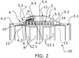
- the ball joint (10) further comprises a bellow (3) as it can be shown on figures 2 and 3 .
- These figures 2 and 3 show a cross sectional view of a portion of the ball joint (10) shown in figure 1 .
- the bellow (3) is housed in the housing and is configured with limited flexure capability to accommodate variations in the angle between the longitudinal axes (X1, X2) of the first (1) and second (2) tubular portions of the duct assembly respectively.
- the housing is configured to hold the tubular portions (1, 2) against axial forces while allows the bellow (3) to flex within predetermined angle limits set by the ball joint (10).
- the inner shroud (4) of the housing further comprises a second end (4.2) arranged over the bellow (3).
- the outer shroud (5) of the housing further comprises a second end (5.2) arranged above the inner shroud (4), specifically, the outer shroud (5) partially overlaps above the inner shroud (4).
- an overlapping interface is provided between the inner shroud (4) and the outer shroud (5), the overlapping interface being understood as the contact surfaces between the shrouds (4, 5) as a result of the outer shroud (5) overlapping above the inner shroud (4).
- the inner shroud (4) also comprises an inner surface (4.3) faced to the bellow (3), and the outer shroud (5) comprises an outer surface (5.3) faced to the outside of the ball joint (10).
- the inner shroud (4) comprises a first thickening (6) located at a region between the first end (4.1) and the second end (4.2) of the inner shroud (4).
- the outer shroud (5) comprises a second thickening (7) located at the second end (5.2) of the outer shroud (5).
- the inner shrouds (4) comprises a spherical portion (4.4) extended between the first end (4.1) and the second end (4.2) of the inner shroud (4).
- the outer shroud (5) comprises a spherical portion (5.4) extended from the second end (5.2) of the outer shroud (5) to a point midway between the first (5.1) and second (5.2) end.
- the first thickening (6) of the inner shroud (4) is a reinforcement ring that is annularly extended along the inner shroud (4) relative to the first longitudinal axis (X1)
- the second thickening (7) of the outer shroud (5) is also a reinforcement ring that in this case is annularly extended along the outer shroud (5) relative to the second longitudinal axis (X2).
- the first thickening (6) is a projection that protrudes from the inner surface (4.3) of the inner shrouds (4) towards the inside of the ball joint (10) or the bellow (3)
- the second thickening (7) is a projection that protrudes from the outer surface (5.3) of the outer shroud (5) towards the outside of the ball joint (10).
- the ball joint (10) shown in these figures 1-3 further comprises a first liner (12) and a second liner (13).
- the first liner (12) is extended cantilevered from the first end (4.1) of the inner shroud (4) as a bracket on which the bellow (3) is supported at one end
- the second liner (13) is extended cantilevered from the first end (5.1) of the outer shroud (5) as a bracket on which the bellow (3) is supported at the other end.
- the bellow is connected to the housing through these liners (12, 13) since it is attached to the liners (12, 13).
- the bellow (3) is attached to the liners (12, 13) by fixing means (14).
- These liners (12, 13) comprises an extension (12.1, 13.1) that partially covers the bellow (3) so that the bellow (3) is housed in a space bounded by the housing of the ball joint (10) and the liners (12, 13) with their respective extensions (12.1, 13.1).
- the bellow (3) is directly attached at one end to the first end (4.1) of the inner shroud (4) and at the other end to the first end (5.1) of the outer shroud (5).
- the bellow (3) is connected to the housing through its direct link to the housing, the bellow (3) being supported by the first ends (4.1, 5.1) of the shrouds (4, 5) respectively.
- the outer shroud (5) is formed by two portions, a spherical portion (5.4) and a remaining portion (5.5) extended from the spherical portion (5.4) to the first end (5.1) of the outer shroud (5).
- Each figure 2 and 3 shows a different example of link between the spherical portion (5.4) and the remaining portion (5.5) of the outer shroud (5). According to figure 2 , the spherical portion (5.4) and the remaining portion (5.5) are joined each other by welding (11).
- the outer shroud (5) comprises a step (5.6) extended from the remaining portion (5.5) and below the spherical portion (5.4) so that a joining end (5.4.1) of the spherical portion (5.4) rests.
- the step (5.6) is provided from an end (5.5.1) of the remaining portion (5.5) where the remaining portion (5.5) is welded to the spherical portion (5.4).
- the ball joint (10) shown in figures 1-3 further comprises a first ribbed pattern (8) on the inner shroud (4) and a second ribbed pattern (9) on the outer shroud (5).
- the first ribbed pattern (8) is indentations arranged annularly on the inner surface (4.3) of the inner shroud (4). These indentations are understood as grooves located on the inner surface (4.3) of the inner shroud (4).
- the second ribbed pattern (9) is projections arranged annularly on the outer surface (5.3) of the outer shroud (5).
- both ribbed patterns (8, 9) has an isogrid configuration.
- the first ribbed pattern (8) is arranged between the first thickening (6) and the second end (4.2) of the inner shroud (4), and particularly on the spherical portion (4.4) of the inner shroud (4).
- the second thickening (9) is arranged downstream of the second end (5.2) of the outer shroud (5), and particularly, on the spherical portion (5.4) of the outer shroud (5).
- the ball joint (10) comprises a rest position where the ball joint (10) is not subjected to flexure stresses, that is, it is not rotated; and a plurality of operating positions where the ball joint (10) is subjected to flexure stresses, that is, it is rotated.
- the rotation of the ball joint (10) that allows the bellow (3) to flex will be deemed to mean when the shrouds (4, 5) of the housing rotate relative to each other as result of the tubular portions (1, 2) of the duct assembly being pressurized. That is, the ball joint rotation refers to bellow flexion rotation and not bellow torsion rotation.
- Figure 4A shows a frontal view of the ball joint (10) (the same as shown in figure 1 ) in a rest position. In this rest position, the overlapping interface between the inner shroud (4) and the outer shroud (5) is annularly constant along the ball joint (10). Further, figures 1-3 shown the ball joint (10) in the rest positions. In the rest position of the ball joint (10) according to an example, the first (8) and second (9) ribbed patterns are partially coincident along the ball joint due to the constant overlapping interface between the shroud (4, 5). Figure 4A also shows the longitudinal axes (X1, X2) that the tubular portions (not shown) of the duct assembly will have. In this case where the ball joint (10) is in the rest position. Both longitudinal axes (X1, X2) are parallel to each other as it is understood that the ducts have not displaced relative to each other and therefore the ball joint (10) has not been subjected to rotation.
- Figure 4B shows a frontal view of the ball joint (10) (the same as shown in figure 1 ) in one operating position.
- the ball joint (10) In this operating position, the ball joint (10) is rotated with respect to its rest position so that the overlapping interface between the shrouds (4, 5) varies annularly along the ball joint (10) while the outer shroud (5) is still overlapping over the inner shroud (4).
- the rotation of the ball joint (10), also referred to the bellow flexion rotation is further shown by the longitudinal axes (X1, X2) that the tubular portions (not shown) will have, in particular, due these longitudinal axes (X1, X2) are not parallel each other as shown in figure 4A of the rest position.
- the rotation of the ball joint (10) shown in figure 4B corresponds to the rotation of the ball joint (10) around a first rotating axis (not shown) such that it leads to the bellow flexure and not to the bellow torsion.
- the overlapping surface between the shrouds (4, 5) increases from the top to the bottom of the ball joint (10).
- Figure 5 shows a cross sectional view of the ball joint (10) in the operating position of figure 4B without showing the bellow for a better view of the ball joint (10).
- the ball joint (10) shown in figure 5 corresponds to the ball joint (10) shown in figures 1 and 2 but without shown the bellow (3).
- the overlapping interface is larger in the bottom of the ball joint (10) than in the top.
- the contact surface between the inner shrouds (4) and the outer shroud (5) is larger in the bottom of the ball joint (10) compared with the top of the ball joint (10) according to the view of this figure 5 .
- the inner (4) and outer (5) shrouds of the ball joint (10) described above in relation with figures 1-5 are 3D printed structures, that is, they have been manufacture by additive manufacturing.
Landscapes
- Engineering & Computer Science (AREA)
- General Engineering & Computer Science (AREA)
- Mechanical Engineering (AREA)
- Chemical & Material Sciences (AREA)
- Combustion & Propulsion (AREA)
- Pivots And Pivotal Connections (AREA)
- Joints Allowing Movement (AREA)
Priority Applications (4)
| Application Number | Priority Date | Filing Date | Title |
|---|---|---|---|
| EP23382096.8A EP4411191A1 (fr) | 2023-02-02 | 2023-02-02 | Joint à rotule |
| CA3225891A CA3225891A1 (fr) | 2023-02-02 | 2024-01-11 | Joint a rotule |
| US18/409,851 US12601431B2 (en) | 2023-02-02 | 2024-01-11 | Ball joint |
| CN202410155584.3A CN118423141A (zh) | 2023-02-02 | 2024-02-02 | 球形接头 |
Applications Claiming Priority (1)
| Application Number | Priority Date | Filing Date | Title |
|---|---|---|---|
| EP23382096.8A EP4411191A1 (fr) | 2023-02-02 | 2023-02-02 | Joint à rotule |
Publications (1)
| Publication Number | Publication Date |
|---|---|
| EP4411191A1 true EP4411191A1 (fr) | 2024-08-07 |
Family
ID=85174113
Family Applications (1)
| Application Number | Title | Priority Date | Filing Date |
|---|---|---|---|
| EP23382096.8A Pending EP4411191A1 (fr) | 2023-02-02 | 2023-02-02 | Joint à rotule |
Country Status (4)
| Country | Link |
|---|---|
| US (1) | US12601431B2 (fr) |
| EP (1) | EP4411191A1 (fr) |
| CN (1) | CN118423141A (fr) |
| CA (1) | CA3225891A1 (fr) |
Citations (4)
| Publication number | Priority date | Publication date | Assignee | Title |
|---|---|---|---|---|
| DE9404481U1 (de) * | 1994-03-16 | 1994-05-26 | Thyssen Polymer GmbH, 81671 München | Gelenkrohr |
| US5611577A (en) * | 1994-12-22 | 1997-03-18 | General Electric Company | Bellows sealed ball joint and method of forming |
| US20150338003A1 (en) * | 2014-05-23 | 2015-11-26 | Waterworks Technology Development Organization Co., Ltd. | Extendable and Contractible Flexible Joint |
| WO2024089318A1 (fr) * | 2022-10-24 | 2024-05-02 | Safran Aerosystems | Raccord rotulaire pour tuyauterie d'un moteur, tuyauterie et aéronef associés |
Family Cites Families (3)
| Publication number | Priority date | Publication date | Assignee | Title |
|---|---|---|---|---|
| US6250690B1 (en) * | 1999-08-26 | 2001-06-26 | Waterworks Technology Development Organization Co., Ltd. | Expansion flexible tube joint and assembling method thereof |
| GB2413977B (en) * | 2004-05-13 | 2006-04-12 | Rolls Royce Plc | Method of manufacturing thin wall isogrid casings |
| JP5998680B2 (ja) * | 2012-07-02 | 2016-09-28 | オイレス工業株式会社 | 球面排気管継手 |
-
2023
- 2023-02-02 EP EP23382096.8A patent/EP4411191A1/fr active Pending
-
2024
- 2024-01-11 CA CA3225891A patent/CA3225891A1/fr active Pending
- 2024-01-11 US US18/409,851 patent/US12601431B2/en active Active
- 2024-02-02 CN CN202410155584.3A patent/CN118423141A/zh active Pending
Patent Citations (4)
| Publication number | Priority date | Publication date | Assignee | Title |
|---|---|---|---|---|
| DE9404481U1 (de) * | 1994-03-16 | 1994-05-26 | Thyssen Polymer GmbH, 81671 München | Gelenkrohr |
| US5611577A (en) * | 1994-12-22 | 1997-03-18 | General Electric Company | Bellows sealed ball joint and method of forming |
| US20150338003A1 (en) * | 2014-05-23 | 2015-11-26 | Waterworks Technology Development Organization Co., Ltd. | Extendable and Contractible Flexible Joint |
| WO2024089318A1 (fr) * | 2022-10-24 | 2024-05-02 | Safran Aerosystems | Raccord rotulaire pour tuyauterie d'un moteur, tuyauterie et aéronef associés |
Also Published As
| Publication number | Publication date |
|---|---|
| CN118423141A (zh) | 2024-08-02 |
| US20240263670A1 (en) | 2024-08-08 |
| US12601431B2 (en) | 2026-04-14 |
| CA3225891A1 (fr) | 2025-04-10 |
Similar Documents
| Publication | Publication Date | Title |
|---|---|---|
| EP1643084B1 (fr) | Segment de virole pour une moteur à turbine et dispositif de suspension | |
| EP1350927B1 (fr) | Segment de virole, procédé de fabrication d'un segment de virole, et virole pour moteur à turbine | |
| EP2192275B1 (fr) | Moteur à turbine à gaz | |
| EP2192276B1 (fr) | Turbine à gaz avec structure de support pour palier | |
| US10907489B2 (en) | Vaned ring for turbomachine stator having vanes connected to an outer shell by conical seating and frangible pin | |
| CN110761855B (zh) | 一种燃气涡轮发动机后机匣 | |
| EP1045959A1 (fr) | Joint d'etancheite annulaire en forme de c | |
| CA2686658A1 (fr) | Systeme de bati de mi-turbine a gaz | |
| US10151209B2 (en) | Sealing system made of ceramic fiber composite materials | |
| CN108302269B (zh) | 球状挠性接头的万向挠曲 | |
| US20170241291A1 (en) | Turbine intermediate casing and sealing arrangement of ceramic fiber composite materials | |
| RU2524831C2 (ru) | Изогнутый шатун, снабженный, по меньшей мере, одним средством самовыравнивания | |
| US9399952B2 (en) | Method for assembling a nozzle and an exhaust case of a turbomachine | |
| US6336789B1 (en) | Casing for a steam or gas turbine | |
| EP4411191A1 (fr) | Joint à rotule | |
| US7430867B2 (en) | Gas turbine multiple sectioned exhaust duct | |
| GB2036888A (en) | Seal vibration-reducing apparatus | |
| US12234930B2 (en) | Multipart pipe joint | |
| HK40110241A (en) | Ball joint | |
| JP7470059B2 (ja) | 航空機用ターボマシンの取付ストラットの一端と、インターフローコンパートメントを区切る前記ターボマシンのカウリングとの間に配置されるように設計された改良型耐火装置 | |
| US7458772B2 (en) | Guide vane ring of a turbomachine and associated modification method | |
| EP3299584A1 (fr) | Turbine à gaz | |
| US20240317415A1 (en) | Propulsion unit comprising pendular bifurcation panels | |
| EP3901412B1 (fr) | Configurations d'enveloppe d'amortisseur | |
| US20260125986A1 (en) | Turbine sealing ring that is removable upstream |
Legal Events
| Date | Code | Title | Description |
|---|---|---|---|
| PUAI | Public reference made under article 153(3) epc to a published international application that has entered the european phase |
Free format text: ORIGINAL CODE: 0009012 |
|
| STAA | Information on the status of an ep patent application or granted ep patent |
Free format text: STATUS: THE APPLICATION HAS BEEN PUBLISHED |
|
| AK | Designated contracting states |
Kind code of ref document: A1 Designated state(s): AL AT BE BG CH CY CZ DE DK EE ES FI FR GB GR HR HU IE IS IT LI LT LU LV MC ME MK MT NL NO PL PT RO RS SE SI SK SM TR |
|
| REG | Reference to a national code |
Ref country code: HK Ref legal event code: DE Ref document number: 40110241 Country of ref document: HK |
|
| STAA | Information on the status of an ep patent application or granted ep patent |
Free format text: STATUS: REQUEST FOR EXAMINATION WAS MADE |
|
| 17P | Request for examination filed |
Effective date: 20250204 |
|
| STAA | Information on the status of an ep patent application or granted ep patent |
Free format text: STATUS: EXAMINATION IS IN PROGRESS |
|
| 17Q | First examination report despatched |
Effective date: 20250527 |