EP4411337A2 - Procédé d'étalonnage de fréquences nominales - Google Patents
Procédé d'étalonnage de fréquences nominales Download PDFInfo
- Publication number
- EP4411337A2 EP4411337A2 EP24171166.2A EP24171166A EP4411337A2 EP 4411337 A2 EP4411337 A2 EP 4411337A2 EP 24171166 A EP24171166 A EP 24171166A EP 4411337 A2 EP4411337 A2 EP 4411337A2
- Authority
- EP
- European Patent Office
- Prior art keywords
- frequency
- rotor blade
- eigenmodes
- operating
- mode
- Prior art date
- Legal status (The legal status is an assumption and is not a legal conclusion. Google has not performed a legal analysis and makes no representation as to the accuracy of the status listed.)
- Withdrawn
Links
Images


Classifications
-
- F—MECHANICAL ENGINEERING; LIGHTING; HEATING; WEAPONS; BLASTING
- F03—MACHINES OR ENGINES FOR LIQUIDS; WIND, SPRING, OR WEIGHT MOTORS; PRODUCING MECHANICAL POWER OR A REACTIVE PROPULSIVE THRUST, NOT OTHERWISE PROVIDED FOR
- F03D—WIND MOTORS
- F03D17/00—Monitoring or testing of wind motors, e.g. diagnostics
-
- F—MECHANICAL ENGINEERING; LIGHTING; HEATING; WEAPONS; BLASTING
- F03—MACHINES OR ENGINES FOR LIQUIDS; WIND, SPRING, OR WEIGHT MOTORS; PRODUCING MECHANICAL POWER OR A REACTIVE PROPULSIVE THRUST, NOT OTHERWISE PROVIDED FOR
- F03D—WIND MOTORS
- F03D1/00—Wind motors with rotation axis substantially parallel to the air flow entering the rotor
- F03D1/06—Rotors
- F03D1/065—Rotors characterised by their construction elements
- F03D1/0675—Rotors characterised by their construction elements of the blades
-
- G—PHYSICS
- G01—MEASURING; TESTING
- G01M—TESTING STATIC OR DYNAMIC BALANCE OF MACHINES OR STRUCTURES; TESTING OF STRUCTURES OR APPARATUS, NOT OTHERWISE PROVIDED FOR
- G01M7/00—Vibration-testing of structures; Shock-testing of structures
- G01M7/02—Vibration-testing by means of a shake table
-
- F—MECHANICAL ENGINEERING; LIGHTING; HEATING; WEAPONS; BLASTING
- F05—INDEXING SCHEMES RELATING TO ENGINES OR PUMPS IN VARIOUS SUBCLASSES OF CLASSES F01-F04
- F05B—INDEXING SCHEME RELATING TO WIND, SPRING, WEIGHT, INERTIA OR LIKE MOTORS, TO MACHINES OR ENGINES FOR LIQUIDS COVERED BY SUBCLASSES F03B, F03D AND F03G
- F05B2270/00—Control
- F05B2270/30—Control parameters, e.g. input parameters
- F05B2270/303—Temperature
-
- F—MECHANICAL ENGINEERING; LIGHTING; HEATING; WEAPONS; BLASTING
- F05—INDEXING SCHEMES RELATING TO ENGINES OR PUMPS IN VARIOUS SUBCLASSES OF CLASSES F01-F04
- F05B—INDEXING SCHEME RELATING TO WIND, SPRING, WEIGHT, INERTIA OR LIKE MOTORS, TO MACHINES OR ENGINES FOR LIQUIDS COVERED BY SUBCLASSES F03B, F03D AND F03G
- F05B2270/00—Control
- F05B2270/30—Control parameters, e.g. input parameters
- F05B2270/32—Wind speeds
-
- F—MECHANICAL ENGINEERING; LIGHTING; HEATING; WEAPONS; BLASTING
- F05—INDEXING SCHEMES RELATING TO ENGINES OR PUMPS IN VARIOUS SUBCLASSES OF CLASSES F01-F04
- F05B—INDEXING SCHEME RELATING TO WIND, SPRING, WEIGHT, INERTIA OR LIKE MOTORS, TO MACHINES OR ENGINES FOR LIQUIDS COVERED BY SUBCLASSES F03B, F03D AND F03G
- F05B2270/00—Control
- F05B2270/30—Control parameters, e.g. input parameters
- F05B2270/328—Blade pitch angle
-
- F—MECHANICAL ENGINEERING; LIGHTING; HEATING; WEAPONS; BLASTING
- F05—INDEXING SCHEMES RELATING TO ENGINES OR PUMPS IN VARIOUS SUBCLASSES OF CLASSES F01-F04
- F05B—INDEXING SCHEME RELATING TO WIND, SPRING, WEIGHT, INERTIA OR LIKE MOTORS, TO MACHINES OR ENGINES FOR LIQUIDS COVERED BY SUBCLASSES F03B, F03D AND F03G
- F05B2270/00—Control
- F05B2270/30—Control parameters, e.g. input parameters
- F05B2270/334—Vibration measurements
-
- F—MECHANICAL ENGINEERING; LIGHTING; HEATING; WEAPONS; BLASTING
- F05—INDEXING SCHEMES RELATING TO ENGINES OR PUMPS IN VARIOUS SUBCLASSES OF CLASSES F01-F04
- F05B—INDEXING SCHEME RELATING TO WIND, SPRING, WEIGHT, INERTIA OR LIKE MOTORS, TO MACHINES OR ENGINES FOR LIQUIDS COVERED BY SUBCLASSES F03B, F03D AND F03G
- F05B2270/00—Control
- F05B2270/80—Devices generating input signals, e.g. transducers, sensors, cameras or strain gauges
- F05B2270/802—Calibration thereof
-
- Y—GENERAL TAGGING OF NEW TECHNOLOGICAL DEVELOPMENTS; GENERAL TAGGING OF CROSS-SECTIONAL TECHNOLOGIES SPANNING OVER SEVERAL SECTIONS OF THE IPC; TECHNICAL SUBJECTS COVERED BY FORMER USPC CROSS-REFERENCE ART COLLECTIONS [XRACs] AND DIGESTS
- Y02—TECHNOLOGIES OR APPLICATIONS FOR MITIGATION OR ADAPTATION AGAINST CLIMATE CHANGE
- Y02E—REDUCTION OF GREENHOUSE GAS [GHG] EMISSIONS, RELATED TO ENERGY GENERATION, TRANSMISSION OR DISTRIBUTION
- Y02E10/00—Energy generation through renewable energy sources
- Y02E10/70—Wind energy
- Y02E10/72—Wind turbines with rotation axis in wind direction
Definitions
- Embodiments of the present invention generally relate to operating modal analysis, and more particularly relate to a method for calibrating nominal frequencies in operating modal analysis. Such a method can be used, for example, to monitor rotor blades of wind turbines or other moving structures with regard to their vibration properties.
- the analysis of the natural frequencies or natural modes of a system provides important information about its structure and vibration behavior, for example. Once these natural frequencies or natural modes are known, deviations can be used to conclude that there is a change in the state of the system structure.
- Many systems have variable operating parameters or are operated under different environmental parameters. This is the case, for example, with rotor blades of wind turbines, where, for example, rotor speed, pitch angle, surface loading, angle of attack, flow velocity, etc. can change within short periods of time.
- external influences i.e. environmental parameters such as wind conditions, temperatures, ice coverage, humidity, etc.
- the natural frequencies and natural modes of the system are therefore dependent on the operating or environmental parameters, with such a dependency being different for each natural frequency or natural mode.
- a method for monitoring an oscillatory system comprising detecting vibration eigenmodes of the oscillatory system as a function of at least one operating parameter and/or as a function of at least one environmental parameter of the oscillatory system; creating a frequency distribution of the detected vibration eigenmodes as a function of a mode frequency and the at least one operating parameter and/or the at least one environmental parameter; as a function of the created frequency distribution, dividing the vibration eigenmodes into frequency classes; and in at least one frequency class, determining a mode curve over the operating parameter and/or over the environmental parameter.
- a method for monitoring an oscillatory system includes: detecting vibration eigenmodes of the oscillatory system as a function of at least one operating parameter and/or as a function of at least one environmental parameter of the oscillatory system in at least one operating range; creating a frequency distribution of the detected vibration eigenmodes as a function of a mode frequency and the at least one operating parameter and/or the at least one environmental parameter in the operating range; as a function of the frequency distribution created, classifying the vibration eigenmodes into frequency classes, wherein the classification of the vibration eigenmodes into frequency classes is carried out by determining a peak value of the frequency distribution of eigenmodes which exceeds a predetermined threshold and which has continuity over the entire operating range; and in at least one frequency class, determining a mode curve over the operating parameter and/or over the environmental parameter.
- a hardware module comprising a computer program designed to carry out the method for monitoring an oscillatory system.
- Figure 1 shows a schematic overview block diagram to explain the method according to an embodiment.
- relevant eigenmodes are automatically detected, automatically divided into operating ranges and the eigenmodes are modeled depending on the operating parameters.
- both operating parameters 101 and environmental parameters 102 can be entered.
- measured eigenmodes 103 are known according to embodiments of the method described below and can also be processed in the analysis step 100.
- the analysis step 100 comprises an operating range classification step 105, which serves to carry out an automatic classification into operating ranges. Furthermore, in the analysis step 100, a modeling of eigenmodes takes place over selected operating parameters and/or environmental parameters in a modeling step 106. After the Figure 1 In the analysis step 100 shown, a calibration and modeling step is carried out which can provide an automated or at least partially automated detection of relevant eigenmodes using the data output from the analysis step 100 on the basis of a frequency distribution 200.
- histograms are used in an automatic calibration of the nominal frequencies in the operating modal analysis.
- Such a histogram is designed in particular not only to show summary measurement data such as an arithmetic mean and an associated standard deviation, but also to indicate a course of the recorded frequency distribution.
- conclusions can thus be drawn about changes in the state of the structure being examined, such as a rotor blade of a wind turbine.
- the dependence of nominal eigenmodes in relation to operating parameters of the structure being examined and/or environmental parameters in the vicinity of the structure being examined can vary for different eigenmodes.
- the creation of a frequency distribution includes the creation of a histogram.
- a histogram represents a clear graphic of the frequency distribution of certain scaled features.
- the measurement data obtained are divided into classes, whereby the classes can have a constant or variable width. This results in areas directly next to one another which have a total content that corresponds to a relative or absolute class frequency.
- a maximum value of an area can represent a relative or absolute frequency density.
- the frequency density can thus define the relative or absolute frequency in relation to the width of the corresponding class.
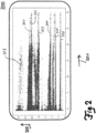
- Figure 2 is a procedure according to the provisions of Figure 1 The histogram obtained in the embodiment shown is presented in more detail.
- Figure 2 illustrates different frequency distributions in specific frequency classes, where the x-axis represents an operating parameter curve 201 and the y-axis a frequency range division 202.
- the x-axis represents an operating parameter curve 201 and the y-axis a frequency range division 202.
- Figure 2 In the measurement shown as an example, clearly different mode curves 301, 302, 303, 304, 305, 306, ... can be seen in different frequency ranges or frequency classes 202.
- curves of the eigenmodes can be modeled using a linear least squares approximation. A polynomial of any degree can be adapted to individual mode curves. It is possible to adapt either just the frequency curve or the combined curve of frequency and mode shape via the individual parameters, ie operating parameters and/or environmental parameters.
- the individual mode curves 301, 302, 303, 304, 305, 306, ... result from the frequency distributions of individual natural frequencies 203, which are recorded as individual measuring points in the Figure 2 shown diagram.
- the natural frequencies 203 are therefore the frequencies actually occurring in the oscillating system.
- the histogram is then used to sort the individual natural frequencies 203 by defining individual frequency classes.
- FIG. 3 finally shows a schematic flow diagram to illustrate a method for monitoring an oscillatory system according to an embodiment.
- the process that runs according to the method starts at a block 401.
- oscillation modes of the oscillatory system are detected depending on at least one operating parameter of the oscillatory system and/or depending on at least one environmental parameter of an environment of the oscillatory system.
- Such detection can be carried out, for example, with oscillation sensors, in particular fiber-optic oscillation sensors, preferably fiber Bragg grating sensors.
- the process proceeds to a block 403 in which a frequency distribution of the detected vibration eigenmodes is determined as a function of a mode frequency and the at least one operating parameter and/or the at least one environmental parameter is created.
- a frequency distribution can be evaluated on the basis of a histogram.
- a mode curve over the operating parameter and/or a mode curve over the environmental parameter is determined in at least one frequency class.
- Such a mode curve can be used for an automatic determination or calibration of nominal modes. This enables an estimation of a behavior or a curve of vibration eigenmodes over the selected parameter.
- the procedure ends in a block 406.
- relevant eigenmodes are identified automatically or semi-automatically, with the entire operating range being divided into frequency classes.
- a model of the eigenmodes can now be provided for each individual class depending on the operating parameters or environmental parameters.
- the relevant eigenmodes are identified.
- the histogram 200 shown of all recorded eigenfrequencies and mode shapes provides the basis for this.
- the rotor speed is plotted on the x-axis in revolutions per minute, while the y-axis shows the frequency classes (frequency ranges) in Hertz.
- Relevant eigenmodes are determined using a peak-finding algorithm, which can be provided, for example, as a kernel density function or a zero-point search in the derivation. Whether an eigenmode is relevant or not depends on whether the peak values of the eigenmodes are clearly distinguishable and/or whether their peak value exceeds a predetermined threshold.
- the monitoring of operating parameters or environmental parameters takes place continuously or discontinuously, ie at certain time intervals.
- the set operating parameters and/or the existing environmental parameters can significantly influence the operation of a wind turbine. For example, It is possible that under unfavourable conditions fluttering movements of one or more rotor blades may occur.
- carrying out a determination of the vibration eigenmodes can include detecting foreign material on a rotor blade of a wind turbine. For example, exposure of a rotor blade to foreign material can be determined by detecting a change in a natural frequency within a frequency class.
- the vibration eigenmodes recorded in a frequency class or the mode curve recorded in a frequency class can be compared with a target value or target values in order to detect deviations in an operating behavior and changes in environmental parameters in the environment of the rotor blade or the wind turbine.
- the at least one operating parameter of the oscillatable system is selected from the group consisting of: a rotor speed, an angle of attack of a rotor blade, an angle of attack, a pitch angle of a rotor blade, a yaw angle of a rotor nacelle, a generator speed, a generator power, and any combination thereof.
- An operating parameter can be, for example, the angle of attack of a rotor blade or the pitch angle.
- the angle of attack is defined with respect to a reference plane.
- the pitch angle can define an angular setting of a rotor blade with respect to a rotor hub on which the rotor blade is rotatably mounted.
- the at least one environmental parameter from the environment of the oscillatable system is selected from the group consisting of: the ambient temperature, an ice coating on a rotor blade, an impact of foreign material on a rotor blade, an air humidity, a wind pressure, a wind direction, a wind speed, a surface loading on a rotor blade, an angle of attack, an airflow velocity, a pressure difference, a rotor blade temperature, a rotor blade stiffness, a rotor blade mass distribution, and any combination thereof.
- a wind pressure can be specified as a surface load at a specific location on a rotor blade.
- the wind speed can specify an absolute wind speed.
- An angle of attack can specify an angle between a plane defined by the rotor blade and a wind direction.
- An airflow velocity can define a relative speed or a relative average speed with which ambient air hits the rotor blade.
- firstly vibration modes of the oscillatory system are recorded as a function of at least one operating parameter and/or as a function of at least one environmental parameter of the oscillatory system.
- Such recording can be carried out, for example, using vibration sensors, in particular fiber-optic vibration sensors.
- the vibration modes After the vibration modes have been recorded, they are represented in a frequency distribution, i.e. a frequency distribution of the recorded vibration modes is created as a function of a mode frequency and the at least one operating parameter and/or the at least one environmental parameter.
- the frequency distribution created now serves as a basis for classifying the vibration eigenmodes into frequency classes.
- the vibration eigenmodes are classified into frequency classes depending on the frequency distribution created. It is then possible to determine a mode progression over the operating parameter and/or over the environmental parameter in the respective frequency classes.
- the method according to one embodiment records the mode progression over the operating parameter, the environmental parameter, or over both the operating parameter and the environmental parameter in at least one frequency class.
- the division into frequency classes or a division of the entire operating range is carried out on the basis of a test in which the continuity of the peak values obtained is checked over the entire range. If jumps occur in certain modes, or if these disappear and new modes appear, the operating range is divided at this point.
- the division of the vibration eigenmodes into frequency classes is carried out by determining the frequency distribution of eigenmodes which exceeds a predetermined threshold.
- a predetermined threshold it is essential that the peak values of the eigenmodes can be distinguished, identifying those peak values which exceed the predetermined threshold.
- the determination of whether an eigenmode is relevant or not can be derived from the fact that the peak values of the eigenmodes are clearly distinguishable and/or that a corresponding peak value exceeds a predetermined threshold.
- the detection of vibrational modes of the oscillatable system takes place with regard to natural frequencies, mode shapes and damping.
- the detection of vibrational modes of the oscillatable system includes detecting natural frequencies and/or mode shapes and/or damping and/or mode angles.
- the detection of vibrational eigenmodes of the oscillatable system can be carried out in combination with at least one of the following: one or more natural frequencies, mode shapes, mode angles and dampings. Frequency and/or mode shapes can thus be fitted via individual parameters such as operating parameters or environmental parameters.
- monitoring of operating parameters of a wind turbine and/or environmental parameters in the surrounding area of the wind turbine on a calibration of nominal frequencies can be carried out from a specific mode curve over one or more operating parameters and/or over one or more environmental parameters.
- nominal modes can be determined by adapting a polynomial of a predetermined order to the frequency curve.
- the eigenmodes are modeled on the basis of a linear least squares process in order to adapt a polynomial of any degree to individual mode curves.
- the method allows an automatic detection of relevant eigenmodes and a determination of the dependencies between individual eigenmodes on the one hand and operating (operational) and environmental parameters (external influences).
- the method allows the inclusion of a detection of an attenuation and/or a mode angle in individual frequency classes.
- the result of a calibration is provided in the form of coefficients of individual polynomials. From these coefficients, the expected values for the natural frequencies, the natural modes and the dampings as well as the mode angles can then be calculated at any time using the current operating parameters and/or the current environmental parameters.
- the choice of the polynomial order is made in such a way that the average expected standard deviation combined from all the natural modes is minimized.
- the expected standard deviation is calculated using a prediction band of the individual polynomials and averaged.
- the method according to embodiments described herein thus allows oscillatory structures to be monitored without having to manually define certain quasi-static operating ranges. It is therefore not necessary to determine constant nominal modes for a single operating range.
- the method according to embodiments described herein thus offers considerable time savings, since an automated or at least partially automated calibration of the nominal frequencies can be provided during the operating modal analysis. The calibration effort can thus be significantly reduced. Only a short check is required to check whether the calibration quality is sufficient. Furthermore, it is possible to improve the quality of the calibration and to provide a way to automatically update calibrations. Thus, a determination of nominal modes and/or nominal frequencies can be carried out depending on the operating parameters and/or environmental parameters, so that detection or monitoring of oscillatory structures is provided in a simple manner.
- the oscillatable system or the oscillatable structure is a rotor blade of a wind turbine.
Landscapes
- Engineering & Computer Science (AREA)
- Mechanical Engineering (AREA)
- Sustainable Development (AREA)
- Sustainable Energy (AREA)
- Chemical & Material Sciences (AREA)
- Combustion & Propulsion (AREA)
- Life Sciences & Earth Sciences (AREA)
- General Engineering & Computer Science (AREA)
- Physics & Mathematics (AREA)
- General Physics & Mathematics (AREA)
- Wind Motors (AREA)
- Measurement Of Mechanical Vibrations Or Ultrasonic Waves (AREA)
- Testing Of Devices, Machine Parts, Or Other Structures Thereof (AREA)
Applications Claiming Priority (3)
| Application Number | Priority Date | Filing Date | Title |
|---|---|---|---|
| DE102017131389.3A DE102017131389B4 (de) | 2017-12-28 | 2017-12-28 | Verfahren zum Kalibrieren von Nominalfrequenzen |
| PCT/EP2018/097078 WO2019129849A1 (fr) | 2017-12-28 | 2018-12-28 | Procédé pour étalonner des fréquences nominales |
| EP18833072.4A EP3732371B1 (fr) | 2017-12-28 | 2018-12-28 | Procédé pour étalonner des fréquences nominales |
Related Parent Applications (2)
| Application Number | Title | Priority Date | Filing Date |
|---|---|---|---|
| EP18833072.4A Division EP3732371B1 (fr) | 2017-12-28 | 2018-12-28 | Procédé pour étalonner des fréquences nominales |
| EP18833072.4A Previously-Filed-Application EP3732371B1 (fr) | 2017-12-28 | 2018-12-28 | Procédé pour étalonner des fréquences nominales |
Publications (2)
| Publication Number | Publication Date |
|---|---|
| EP4411337A2 true EP4411337A2 (fr) | 2024-08-07 |
| EP4411337A3 EP4411337A3 (fr) | 2024-10-30 |
Family
ID=65010768
Family Applications (2)
| Application Number | Title | Priority Date | Filing Date |
|---|---|---|---|
| EP24171166.2A Withdrawn EP4411337A3 (fr) | 2017-12-28 | 2018-12-28 | Procédé d'étalonnage de fréquences nominales |
| EP18833072.4A Active EP3732371B1 (fr) | 2017-12-28 | 2018-12-28 | Procédé pour étalonner des fréquences nominales |
Family Applications After (1)
| Application Number | Title | Priority Date | Filing Date |
|---|---|---|---|
| EP18833072.4A Active EP3732371B1 (fr) | 2017-12-28 | 2018-12-28 | Procédé pour étalonner des fréquences nominales |
Country Status (7)
| Country | Link |
|---|---|
| US (1) | US11105318B2 (fr) |
| EP (2) | EP4411337A3 (fr) |
| CN (1) | CN111527303B (fr) |
| CA (1) | CA3085503C (fr) |
| DE (1) | DE102017131389B4 (fr) |
| ES (1) | ES2980058T3 (fr) |
| WO (1) | WO2019129849A1 (fr) |
Families Citing this family (2)
| Publication number | Priority date | Publication date | Assignee | Title |
|---|---|---|---|---|
| DE102020105053A1 (de) * | 2020-02-26 | 2021-08-26 | fos4X GmbH | Verfahren zur Zustandsüberwachung eines Antriebsstrangs oder Turms einer Windenergieanlage und Windenergieanlage |
| DE102021120494B3 (de) * | 2021-08-06 | 2023-01-26 | Sandvik Mining and Construction Deutschland GmbH | Verfahren und vorrichtung zur resonanzanalyse einer schwingmaschine |
Family Cites Families (31)
| Publication number | Priority date | Publication date | Assignee | Title |
|---|---|---|---|---|
| US7224077B2 (en) * | 2004-01-14 | 2007-05-29 | Ocean Power Technologies, Inc. | Bluff body energy converter |
| JP5172077B2 (ja) * | 2005-05-06 | 2013-03-27 | アズビル株式会社 | 距離・速度計および距離・速度計測方法 |
| GB0523455D0 (en) * | 2005-11-18 | 2005-12-28 | Renishaw Plc | Dynamic air turbulence compensation |
| GB0525989D0 (en) * | 2005-12-21 | 2006-02-01 | Qinetiq Ltd | Generation of electrical power from fluid flows |
| US20070176430A1 (en) * | 2006-02-01 | 2007-08-02 | Hammig Mark D | Fluid Powered Oscillator |
| US20080048455A1 (en) * | 2006-08-25 | 2008-02-28 | Matthew Eli Carney | Energy capture in flowing fluids |
| DE102006054666B4 (de) * | 2006-11-17 | 2010-01-14 | Repower Systems Ag | Schwingungsdämpfung einer Windenergieanlage |
| EP1953567A3 (fr) * | 2007-01-25 | 2010-09-22 | Yamatake Corporation | Dispositif de comptage, mesure de distance, procédé de comptage, et procédé de mesure de distance |
| CZ2007331A3 (cs) * | 2007-05-09 | 2008-12-29 | Vysoké ucení technické Brno | Elektromagnetický vibracní generátor pro nízké frekvence vibrací |
| US7649631B2 (en) * | 2007-06-06 | 2010-01-19 | Yamatake Corporation | Distance/speed meter and distance/speed measuring method |
| JP5545916B2 (ja) * | 2008-01-31 | 2014-07-09 | アズビル株式会社 | 物理量センサおよび物理量計測方法 |
| JP5663148B2 (ja) * | 2009-06-29 | 2015-02-04 | アズビル株式会社 | 計数装置、物理量センサ、計数方法および物理量計測方法 |
| JP2011033525A (ja) * | 2009-08-04 | 2011-02-17 | Yamatake Corp | 計数装置、物理量センサ、計数方法および物理量計測方法 |
| US9464623B2 (en) * | 2009-09-17 | 2016-10-11 | Western Michigan University Research Foundation | Method and device for power generation |
| JP5702536B2 (ja) * | 2010-01-05 | 2015-04-15 | アズビル株式会社 | 速度計測装置および方法 |
| US8982336B2 (en) * | 2010-03-10 | 2015-03-17 | Azbil Corporation | Physical quantity sensor and physical quantity measuring method |
| US8537341B2 (en) * | 2010-03-16 | 2013-09-17 | Azbil Corporation | Physical quantity sensor and physical quantity measuring method |
| ES2374233B8 (es) * | 2010-08-02 | 2013-02-27 | Deutecno S.L. | Aerogenerador resonante por vorticidad. |
| US9326698B2 (en) * | 2011-02-18 | 2016-05-03 | The Trustees Of The University Of Pennsylvania | Method for automatic, unsupervised classification of high-frequency oscillations in physiological recordings |
| US9222465B2 (en) * | 2011-04-15 | 2015-12-29 | Northeastern University | Non-rotating wind energy generator |
| EP2746885A1 (fr) | 2012-12-18 | 2014-06-25 | Alstom Wind, S.L.U. | Procédé de surveillance de l'état d'une éolienne |
| DE102013202261A1 (de) | 2013-02-12 | 2014-08-28 | Senvion Se | Verfahren zum Überprüfen des Betriebs einer Windenergieanlage und Windenergieanlage |
| US20160013737A1 (en) * | 2013-03-06 | 2016-01-14 | Deutecno S.L. | Electrical Energy Generator and Method of Generating Electrical Energy |
| WO2015085465A1 (fr) * | 2013-12-09 | 2015-06-18 | General Electric Company | Système et procédé pour réduire des charges d'oscillation de turbine éolienne |
| CN104075795B (zh) * | 2014-06-18 | 2017-11-21 | 北京金风科创风电设备有限公司 | 用于监测风力发电机组的叶轮振动状态的方法和系统 |
| EP3204635B1 (fr) * | 2014-10-06 | 2020-05-06 | Vortex Bladeless, S.L. | Générateur électrique et méthode de génération électrique |
| DE102014117918A1 (de) | 2014-12-04 | 2016-06-09 | fos4X GmbH | Verfahren zur individuellen Pitchregelung von Rotorblättern einer Windkraftanlage, Beschleunigungssensor für ein Rotorblatt, Rotorblatt mit Beschleunigungssensor, ein Rotor einer Windkraftanlage und Windkraftanlagen |
| WO2017174161A1 (fr) * | 2016-04-07 | 2017-10-12 | Vortex Bladeless, S.L. | Générateur d'énergie électrique |
| EP3642481B1 (fr) * | 2017-06-20 | 2021-05-12 | Vestas Wind Systems A/S | Procédé de détermination de récurrence de charge dans le sens de la traînée de pale d'éolienne |
| CN107171345B (zh) * | 2017-07-03 | 2019-11-05 | 云南电网有限责任公司 | 用于分析不确定参数对电力系统超低频振荡影响的方法 |
| US10982648B2 (en) * | 2019-03-30 | 2021-04-20 | Ehsan Azadi Yazdi | Bladeless wind turbine with a telescoping natural frequency tuning mechanism |
-
2017
- 2017-12-28 DE DE102017131389.3A patent/DE102017131389B4/de active Active
-
2018
- 2018-06-28 US US16/958,749 patent/US11105318B2/en active Active
- 2018-12-28 EP EP24171166.2A patent/EP4411337A3/fr not_active Withdrawn
- 2018-12-28 CA CA3085503A patent/CA3085503C/fr active Active
- 2018-12-28 ES ES18833072T patent/ES2980058T3/es active Active
- 2018-12-28 WO PCT/EP2018/097078 patent/WO2019129849A1/fr not_active Ceased
- 2018-12-28 CN CN201880083928.7A patent/CN111527303B/zh active Active
- 2018-12-28 EP EP18833072.4A patent/EP3732371B1/fr active Active
Also Published As
| Publication number | Publication date |
|---|---|
| WO2019129849A1 (fr) | 2019-07-04 |
| DE102017131389B4 (de) | 2022-05-05 |
| ES2980058T3 (es) | 2024-09-27 |
| US20200332774A1 (en) | 2020-10-22 |
| CA3085503C (fr) | 2023-09-12 |
| DE102017131389A1 (de) | 2019-07-04 |
| EP4411337A3 (fr) | 2024-10-30 |
| EP3732371A1 (fr) | 2020-11-04 |
| US11105318B2 (en) | 2021-08-31 |
| EP3732371B1 (fr) | 2024-04-24 |
| CN111527303B (zh) | 2024-06-07 |
| CN111527303A (zh) | 2020-08-11 |
| CA3085503A1 (fr) | 2019-07-04 |
| EP3732371C0 (fr) | 2024-04-24 |
Similar Documents
| Publication | Publication Date | Title |
|---|---|---|
| DE10065314B4 (de) | Verfahren und Einrichtung zur Überwachung des Zustandes von Rotorblättern an Windkraftanlagen | |
| EP2021890B1 (fr) | Procede de surveillance des contraintes de pales de rotor d'eoliennes | |
| EP2565444B1 (fr) | Procédé et dispositif de surveillance d'état de pales de rotor | |
| DE102010053523B4 (de) | Verfahren zur Überwachung einer statischen und/oder dynamischen Stabilität einer Windenergieanlage | |
| EP3227690B1 (fr) | Procédé pour surveiller une éolienne, procédé pour détecter la présence de givre sur une éolienne, capteur d'accélération pour une pale de rotor, pale de rotor équipée d'un capteur d'accélération, et profil pour une pale de rotor | |
| EP1197417B1 (fr) | Méthode et appareil pour détecter des défauts sur les roues d' un véhicule ferroviaire | |
| DE69406096T2 (de) | Verfahren und Vorrichtung zum Bestimmen einer Lastdimensionierungsüberschreitung eines Flugzeuges | |
| EP2511524A1 (fr) | Procédé et dispositif de surveillance d'une pale de rotor pour une éolienne | |
| WO2002053910A1 (fr) | Procede et dispositif servant a surveiller l'etat de pales de rotor d'installations eoliennes | |
| CN109885854A (zh) | 基于arma模型的颤振边界实时预测系统及预测方法 | |
| WO2018050697A1 (fr) | Procédé et dispositif pour surveiller un état d'au moins une éolienne et produit-programme d'ordinateur | |
| EP2404059A2 (fr) | Procédé de surveillance d'éoliennes | |
| WO2010054644A2 (fr) | Procédé et dispositif de détection de fissures sur des aubes mobiles d'un compresseur | |
| EP2985454A1 (fr) | Procédé de vérification d'un système de détection de glace sur les pâles d'un rotor ainsi que système de détection de glace sur les pâles d'un rotor et éolienne destinée à l'exécution du procédé | |
| DE102019217740B3 (de) | Verfahren und Anordnung zur Überprüfung eines Zustands eines Koordinatenmessgeräts oder eines Drehtisches | |
| EP3732371B1 (fr) | Procédé pour étalonner des fréquences nominales | |
| DE102011016868A1 (de) | Messvorrichtung zum Messen von Verformungen elastisch verformbarer Objekte | |
| DE102022105681A1 (de) | Verfahren zur Ermittlung einer Schwingung eines Lüftungssystems | |
| DE102010009941A1 (de) | Verfahren zum Überwachen von Windturbinen | |
| WO2021122865A1 (fr) | Procédé de détermination de données de fonctionnement d'une éolienne | |
| EP4097440B1 (fr) | Procédé et surface utilisateur graphique pour l'analyse d'un objet mécanique | |
| DE102018102789B4 (de) | Verfahren und Vorrichtung zur Schwingungsanalyse eines schwingungsfähigen Objekts, insbesondere eines Bauwerks | |
| DE102020105053A1 (de) | Verfahren zur Zustandsüberwachung eines Antriebsstrangs oder Turms einer Windenergieanlage und Windenergieanlage | |
| DE60319245T2 (de) | Verfahren und einrichtung zur bestimmung des zustands einer turbinenschaufel und zur verwendung der gesammelten informationen zur schätzung der lebensdauer der schaufel | |
| DE102020127738A1 (de) | Verfahren zur Überwachung einer Rauigkeit zumindest eines Rotorblatts einer Windkraftanlage |
Legal Events
| Date | Code | Title | Description |
|---|---|---|---|
| PUAI | Public reference made under article 153(3) epc to a published international application that has entered the european phase |
Free format text: ORIGINAL CODE: 0009012 |
|
| STAA | Information on the status of an ep patent application or granted ep patent |
Free format text: STATUS: THE APPLICATION HAS BEEN PUBLISHED |
|
| AC | Divisional application: reference to earlier application |
Ref document number: 3732371 Country of ref document: EP Kind code of ref document: P |
|
| AK | Designated contracting states |
Kind code of ref document: A2 Designated state(s): AL AT BE BG CH CY CZ DE DK EE ES FI FR GB GR HR HU IE IS IT LI LT LU LV MC MK MT NL NO PL PT RO RS SE SI SK SM TR |
|
| REG | Reference to a national code |
Ref country code: DE Ref legal event code: R079 Free format text: PREVIOUS MAIN CLASS: G01M0007020000 Ipc: F03D0017000000 |
|
| PUAL | Search report despatched |
Free format text: ORIGINAL CODE: 0009013 |
|
| AK | Designated contracting states |
Kind code of ref document: A3 Designated state(s): AL AT BE BG CH CY CZ DE DK EE ES FI FR GB GR HR HU IE IS IT LI LT LU LV MC MK MT NL NO PL PT RO RS SE SI SK SM TR |
|
| RIC1 | Information provided on ipc code assigned before grant |
Ipc: G01M 7/02 20060101ALI20240923BHEP Ipc: F03D 17/00 20160101AFI20240923BHEP |
|
| STAA | Information on the status of an ep patent application or granted ep patent |
Free format text: STATUS: THE APPLICATION IS DEEMED TO BE WITHDRAWN |
|
| 18D | Application deemed to be withdrawn |
Effective date: 20250501 |