EP4411392A1 - Circuit et procédé de mesure de tension, carte de circuit imprimé et module de commande - Google Patents
Circuit et procédé de mesure de tension, carte de circuit imprimé et module de commande Download PDFInfo
- Publication number
- EP4411392A1 EP4411392A1 EP21967675.6A EP21967675A EP4411392A1 EP 4411392 A1 EP4411392 A1 EP 4411392A1 EP 21967675 A EP21967675 A EP 21967675A EP 4411392 A1 EP4411392 A1 EP 4411392A1
- Authority
- EP
- European Patent Office
- Prior art keywords
- voltage measurement
- voltage
- low
- circuit
- control module
- Prior art date
- Legal status (The legal status is an assumption and is not a legal conclusion. Google has not performed a legal analysis and makes no representation as to the accuracy of the status listed.)
- Pending
Links
Images



Classifications
-
- G—PHYSICS
- G01—MEASURING; TESTING
- G01R—MEASURING ELECTRIC VARIABLES; MEASURING MAGNETIC VARIABLES
- G01R31/00—Arrangements for testing electric properties; Arrangements for locating electric faults; Arrangements for electrical testing characterised by what is being tested not provided for elsewhere
- G01R31/36—Arrangements for testing, measuring or monitoring the electrical condition of accumulators or electric batteries, e.g. capacity or state of charge [SoC]
- G01R31/385—Arrangements for measuring battery or accumulator variables
-
- G—PHYSICS
- G01—MEASURING; TESTING
- G01R—MEASURING ELECTRIC VARIABLES; MEASURING MAGNETIC VARIABLES
- G01R1/00—Details of instruments or arrangements of the types included in groups G01R5/00 - G01R13/00 and G01R31/00
- G01R1/20—Modifications of basic electric elements for use in electric measuring instruments; Structural combinations of such elements with such instruments
- G01R1/206—Switches for connection of measuring instruments or electric motors to measuring loads
-
- G—PHYSICS
- G01—MEASURING; TESTING
- G01R—MEASURING ELECTRIC VARIABLES; MEASURING MAGNETIC VARIABLES
- G01R19/00—Arrangements for measuring currents or voltages or for indicating presence or sign thereof
- G01R19/0084—Measuring voltage only
-
- G—PHYSICS
- G01—MEASURING; TESTING
- G01R—MEASURING ELECTRIC VARIABLES; MEASURING MAGNETIC VARIABLES
- G01R19/00—Arrangements for measuring currents or voltages or for indicating presence or sign thereof
- G01R19/10—Measuring sum, difference or ratio
-
- G—PHYSICS
- G01—MEASURING; TESTING
- G01R—MEASURING ELECTRIC VARIABLES; MEASURING MAGNETIC VARIABLES
- G01R19/00—Arrangements for measuring currents or voltages or for indicating presence or sign thereof
- G01R19/165—Indicating that current or voltage is either above or below a predetermined value or within or outside a predetermined range of values
- G01R19/16533—Indicating that current or voltage is either above or below a predetermined value or within or outside a predetermined range of values characterised by the application
- G01R19/16538—Indicating that current or voltage is either above or below a predetermined value or within or outside a predetermined range of values characterised by the application in AC or DC supplies
- G01R19/16542—Indicating that current or voltage is either above or below a predetermined value or within or outside a predetermined range of values characterised by the application in AC or DC supplies for batteries
-
- G—PHYSICS
- G01—MEASURING; TESTING
- G01R—MEASURING ELECTRIC VARIABLES; MEASURING MAGNETIC VARIABLES
- G01R31/00—Arrangements for testing electric properties; Arrangements for locating electric faults; Arrangements for electrical testing characterised by what is being tested not provided for elsewhere
- G01R31/36—Arrangements for testing, measuring or monitoring the electrical condition of accumulators or electric batteries, e.g. capacity or state of charge [SoC]
- G01R31/374—Arrangements for testing, measuring or monitoring the electrical condition of accumulators or electric batteries, e.g. capacity or state of charge [SoC] with means for correcting the measurement for temperature or ageing
-
- G—PHYSICS
- G01—MEASURING; TESTING
- G01R—MEASURING ELECTRIC VARIABLES; MEASURING MAGNETIC VARIABLES
- G01R31/00—Arrangements for testing electric properties; Arrangements for locating electric faults; Arrangements for electrical testing characterised by what is being tested not provided for elsewhere
- G01R31/36—Arrangements for testing, measuring or monitoring the electrical condition of accumulators or electric batteries, e.g. capacity or state of charge [SoC]
- G01R31/382—Arrangements for monitoring battery or accumulator variables, e.g. SoC
- G01R31/3835—Arrangements for monitoring battery or accumulator variables, e.g. SoC involving only voltage measurements
-
- G—PHYSICS
- G01—MEASURING; TESTING
- G01R—MEASURING ELECTRIC VARIABLES; MEASURING MAGNETIC VARIABLES
- G01R31/00—Arrangements for testing electric properties; Arrangements for locating electric faults; Arrangements for electrical testing characterised by what is being tested not provided for elsewhere
- G01R31/36—Arrangements for testing, measuring or monitoring the electrical condition of accumulators or electric batteries, e.g. capacity or state of charge [SoC]
- G01R31/396—Acquisition or processing of data for testing or for monitoring individual cells or groups of cells within a battery
-
- H—ELECTRICITY
- H01—ELECTRIC ELEMENTS
- H01M—PROCESSES OR MEANS, e.g. BATTERIES, FOR THE DIRECT CONVERSION OF CHEMICAL ENERGY INTO ELECTRICAL ENERGY
- H01M10/00—Secondary cells; Manufacture thereof
- H01M10/42—Methods or arrangements for servicing or maintenance of secondary cells or secondary half-cells
- H01M10/48—Accumulators combined with arrangements for measuring, testing or indicating the condition of cells, e.g. the level or density of the electrolyte
-
- H—ELECTRICITY
- H02—GENERATION; CONVERSION OR DISTRIBUTION OF ELECTRIC POWER
- H02J—ELECTRIC POWER NETWORKS; CIRCUIT ARRANGEMENTS OR SYSTEMS FOR SUPPLYING OR DISTRIBUTING ELECTRIC POWER; SYSTEMS FOR STORING ELECTRIC ENERGY
- H02J7/00—Circuit arrangements for charging or discharging batteries or for supplying loads from batteries
- H02J7/80—Circuit arrangements for charging or discharging batteries or for supplying loads from batteries including monitoring or indicating arrangements
Definitions
- the present application relates to the field of battery technologies, and in particular to a voltage measurement circuit and method, a circuit board, and a control module.
- Embodiments of the present application provide a voltage measurement circuit and method, a circuit board, and a control module, which enable large-range measurement and measurement precision to be balanced.
- embodiments of the present application provides a voltage measurement circuit for measuring a voltage output by a battery, the battery comprising n battery cells connected in series, wherein n is an integer greater than 1; and the circuit comprising: n low-voltage measurement modules provided in one-to-one correspondence with the n battery cells, a first switching circuit, a second switching circuit, a reference voltage source, and a control module, wherein the reference voltage source is used for outputting a preset reference voltage; the two ends of each of the low-voltage measurement modules are connected to the two ends of a corresponding one of the battery cells via the first switching circuit, the two ends of each of the low-voltage measurement modules are further connected to the two ends of the reference voltage source via the second switching circuit, and the control module is connected to switching units in the first switching circuit and the second switching circuit, and the control module is further connected to each of the low-voltage measurement modules; and the control module is used for controlling the switching units to be on or off and acquiring the voltages of the battery cells that are
- the voltages across the n battery cells in the battery can be measured by the n low-voltage measurement modules, respectively, and the measured voltages can be summed up as the voltage output by the battery that is obtained through measurement, which not only expands the measurement range of the voltage measurement circuit, but also ensures that the measurement precision of the summed voltage is close to that of the low-voltage measurement module, so that the large-range measurement and the measurement precision can be balanced.
- embodiments of the present application can also use a reference voltage source to calibrate each of the low-voltage measurement modules, which can further improve the accuracy of voltage measurement by the measurement device.
- the first switching circuit comprises n+1 first switching units; and n-1 connection nodes formed by series connection of the n low-voltage measurement modules and the two ends of a branch circuit formed by series connection of the n low-voltage measurement modules are used as first connectable nodes, and n-1 connection nodes formed by series connection of the n battery cells and the two ends of a branch circuit formed by series connection of the n battery cells are used as second connectable nodes, the first connectable nodes being separately connected to corresponding ones of the second connectable nodes via the first switching units.
- the second switching circuit comprises n+2 second switching units; and n-1 connection nodes formed by series connection of n second switching units and the two ends of a branch circuit formed by series connection of n second switching units are used as third connectable nodes, the first connectable nodes being separately connected to corresponding ones of the third connectable nodes via the second switching units, and the two ends of a branch circuit formed by series connection of the second switching units are further connected to the two ends of the reference voltage source via the second switching units.
- the second switching circuit comprises 2n second switching units; and the two ends of each of the n low-voltage measurement modules are connected at the two ends of the reference voltage source via the second switching units.
- another specific circuit structure of the second switching circuit is provided that allows the voltage across the reference voltage source to be measured by the low-voltage measurement modules simultaneously, thus reducing the time to acquire the error values corresponding to the low-voltage measurement modules.
- control module is specifically used for controlling switching units in the second switching circuit, so as to control switching units in the first switching circuit in the case where the low-voltage measurement modules are all disconnected from the reference voltage source, and to obtain voltages U 1 , U 2 , ..., and U n of the corresponding battery cells through measurement by the low-voltage measurement modules; the control module is further used for controlling the switching units in the first switching circuit, so as to control the switching units in the second switching circuit in the case where the low-voltage measurement modules are all disconnected from the battery cells, and to obtain voltages V 1 , V 2 , ..., and V n output by the reference voltage source through measurement by the low-voltage measurement modules, respectively; and the control module is further used for calculating differences between V 1 , V 2 , ..., and V n and the preset reference voltage separately to obtain errors ⁇ v1 , ⁇ v2 , ..., and ⁇ vn of the low-voltage measurement modules, and calibrating U 1 , U 2 , ..., and
- the voltage measurement circuit further comprises a high-voltage measurement module, the two ends of the high-voltage measurement module being connected to the two ends of the battery, and the control module being further connected to the high-voltage measurement module, wherein the high-voltage measurement module is used for measuring the voltage output by the battery to obtain V total ; and the control module is specifically used for using U sum as the voltage output by the battery that is obtained through measurement when
- the measurement circuit in order to avoid the situation where the measured value keeps changing due to the too high precision of the low-voltage measurement module, the measurement circuit is also provided with a high-voltage measurement module with lower accuracy for directly measuring the voltage output by the battery, and only when the absolute value of the difference between the voltage V total measured by the high-voltage measurement module and U sum is greater than the permissible error of the high-voltage measurement module, the U sum measured by the low-voltage measurement module is used as the voltage output by the battery that is obtained through measurement.
- > ⁇ allow and ⁇ vN ⁇ 0 ; calibrating U 1 , U 2 , ..., and U n according to the equation U n ' U n +
- > ⁇ allow and ⁇ vN ⁇ 0; and setting U n ' U n when
- ⁇ allow is the smaller one of a first permissible error and a second permissible error, wherein the first permissible error is the maximum permissible error of the low-voltage measurement modules and the second permissible error is
- the set permissible error ⁇ allow of the low-voltage measurement module is specifically the maximum permissible error of the low-voltage measurement module, and the maximum permissible error of the high-voltage measurement module is assigned with the smaller one of the second permissible errors on the low-voltage measurement modules, so that when the error satisfies ⁇ allow , the error requirements of both the low-voltage measurement module and the high-voltage measurement module can definitely be satisfied.
- setting the preset reference voltage to be the average value of V 1 , V 2 , ..., and V n can make the preset reference voltage close to the interval in which the voltages of the battery cells are located, thus reducing the adjustment magnitude of each low-voltage measurement device and also reducing the time spent on adjustment.
- embodiments of the present application provide a voltage measurement method that is based on a control module in any of the voltage measurement circuits described above, the method comprising: controlling switching units in a first switching circuit and a second switching circuit to be on or off, and acquiring voltages of battery cells that are measured by low-voltage measurement modules.
- controlling switching units in a first switching circuit and a second switching circuit to be on or off, and acquiring voltages of battery cells that are measured by low-voltage measurement modules comprises: controlling switching units in the second switching circuit, so as to control switching units in the first switching circuit in the case where the low-voltage measurement modules are all disconnected from the reference voltage source, and to obtain voltages U 1 , U 2 , ..., and U n of the corresponding battery cells through measurement by the low-voltage measurement modules; the method further comprises: controlling the switching units in the first switching circuit, so as to control the switching units in the second switching circuit in the case where the low-voltage measurement modules are all disconnected from the battery cells, and to obtain voltages V 1 , V 2 , ..., and V n output by the reference voltage source through measurement by the low-voltage measurement modules, respectively; calculating differences between V 1 , V 2 , ..., and V n and the preset reference voltage output by the reference voltage source separately to obtain errors ⁇ v1 , ⁇ v2
- the voltage measurement circuit further comprises a high-voltage measurement module, the two ends of the high-voltage measurement module being connected to the two ends of the battery, and the control module being further connected to the high-voltage measurement module, wherein the high-voltage measurement module is used for measuring the voltage output by the battery to obtain V total ; and using U sum obtained by summing up U 1 ', U 2 ', ..., and U n ' as a voltage output by the battery that is obtained through measurement comprises: using U sum as the voltage output by the battery that is obtained through measurement when
- > ⁇ allow and ⁇ vN ⁇ 0 ; calibrating U 1 , U 2 , ..., and U n according to the equation U n ' U n +
- > ⁇ allow and ⁇ vN ⁇ 0 ; and setting U n ' U n when
- ⁇ allow is the smaller one of a first permissible error and a second permissible error, wherein the first permissible error is the maximum permissible error of the low-voltage measurement modules and the second permissible error is
- embodiments of the present application provide a circuit board, comprising a voltage measurement circuit in the above mentioned implementations.
- embodiments of the present application provide a control module, comprising: at least one processor; and a memory communicatively connected to the at least one processor, wherein the memory stores instructions executable by the at least one processor, the instructions, when executed by the at least one processor, cause the at least one processor to perform the voltage measurement method described above.
- Battery voltage is one of the most basic monitoring parameters of battery systems.
- Battery voltage can be used for high-voltage fault diagnosis, relay diagnosis, charge and discharge management, and battery safety warning, and other aspects. These functions can not be achieved without accurate and reliable voltage measurements, and at present, changes in the precision of voltage measurements lack the necessary continuous monitoring and correction, and the reliability is not high.
- a battery used in a new energy vehicle is usually made of multiple battery cells connected in series and parallel, and the voltage of the battery is usually high, so a large-range measuring instrument is needed to measure them, but the precision of the large-range measuring instrument is low, so it is difficult to meet the requirements for the measurement precision of the battery voltage.
- the present application proposes the following technical idea: for a battery formed by a plurality of battery cells connected in series, specifically, the voltages of the battery cells are measured separately by a plurality of low-voltage measurement modules with small range but high precision, and the measured voltages of the battery cells are summed up as the measured voltage of the battery, so as to balance the large range and high accuracy of the measured voltage.
- a reference voltage source with higher precision compared to the low-voltage measurement modules can also be used to calibrate each low-voltage measurement module to further ensure the measurement precision of the voltage measurement circuit.
- a high-voltage measurement module with a large range but smaller precision can also be provided to directly measure the voltage of the battery, and the measured voltage of the battery that is calculated according to the low-voltage measurement modules can be used as a standard to calibrate the high-voltage measurement module when the measurement error of the high-voltage measurement module is too large, while when the measurement error is within a permissible range, the measurement result of the high-voltage measurement module is used directly.
- Embodiments of the present application provides a voltage measurement circuit for measuring a voltage output by a battery.
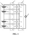
- the battery 1 comprises n battery cells C 1 -C n connected in series, wherein n is an integer greater than 1; and the voltage measurement circuit comprises: n low-voltage measurement modules V 1 -V n provided in one-to-one correspondence with the n battery cells C 1 -C n , a first switching circuit 2, a second switching circuit 3, a reference voltage source 4, and a control module (the control module is not shown in the figure), wherein the reference voltage source 4 is used for outputting a preset reference voltage; the two ends of each of the low-voltage measurement modules are connected to the two ends of the corresponding battery cell via the first switching circuit 2, the two ends of each of the low-voltage measurement modules are further connected to the two ends of the reference voltage source 4 via the second switching circuit 3, the control module is connected to switching units in the first switching circuit 2 and the second switching circuit 3, and the control module is further connected to each of
- the control module is used for controlling the switching units in the first switching circuit 2 and the second switching circuit 3 to be on or off, and acquiring voltages of battery cells that are measured by low-voltage measurement modules.
- the low-voltage measurement module may be a small-range voltage sensor, for example, a small-range voltmeter.
- the reference voltage source may be a programmable high-precision reference voltage source generation module, which can generate high-precision reference voltages of different voltage values according to actual needs, and the voltage values can be adjusted by programming.
- the first switching circuit and the second switching circuit are circuits separately formed by a plurality of switching units connected in series and/or in parallel, wherein the switching units are, for example, knife switches or relays.
- the low-voltage measurement modules are connected to the corresponding battery cells via the first switching circuit, the low-voltage measurement modules are further connected to the reference voltage source via the second switching circuit, and the control module can control whether the low-voltage measurement modules measure the voltages of the battery cells or the voltage of the reference voltage source by controlling the on and off of the switching units in the first switching circuit and the second switching circuit.
- the low-voltage measurement modules measure the voltages of the battery cells
- the low-voltage measurement modules measure the voltage of the reference voltage source, at which time the output voltage of the reference voltage source and the voltages measured by the low-voltage measurement modules can be used to calibrate the low-voltage measurement modules.
- the voltages across the n battery cells in the battery can be measured by the n low-voltage measurement modules, respectively, and the measured voltages can be summed up as the voltage output by the battery that is obtained through measurement, which not only expands the measurement range of the voltage measurement circuit, but also ensures that the measurement precision of the summed voltage is close to that of the low-voltage measurement module, so that the large-range measurement and the measurement precision can be balanced.
- embodiments of the present application can also use a reference voltage source to calibrate each of the low-voltage measurement modules, which can further improve the accuracy of voltage measurement by the measurement device.
- the first switching circuit 2 comprises n+1 first switching units S 0 -S n .
- N-1 connection nodes formed by series connection of the n low-voltage measurement modules V 1 -V n and the two ends of a branch circuit formed by series connection of the n low-voltage measurement modules V 1 -V n are used as first connectable nodes
- n-1 connection nodes formed by series connection of the n battery cells C 1 -C n and the two ends of a branch circuit formed by series connection of the n battery cells C 1 -C n are used as second connectable nodes, the first connectable nodes being separately connected to corresponding ones of the second connectable nodes via the first switching units.
- n-1 connection nodes are formed on a branch circuit formed by the sequential series connection of the n low-voltage measurement modules.
- a connection node here can be considered as a node located on the connection line between any two low-voltage measurement modules connected on the branch circuit.
- the first connectable nodes comprise these n-1 connection nodes, as well as two endpoints (as two nodes) of the branch circuit formed by series connection of the n low-voltage measurement modules, and it can be seen that there are a total of n+1 first connectable nodes.
- connection nodes On a branch circuit formed by the sequential series connection of the n battery cells, n-1 connection nodes are formed.
- a connection node here can be considered as a node located on the connection line between any two battery cells connected on the branch circuit.
- the second connectable nodes comprise these n-1 connectable nodes, as well as two endpoints (as two nodes) of the branch circuit formed by series connection of the n battery cells, and it is seen that there are a total of n+1 second connectable nodes.
- the two ends of a low-voltage measurement module can also be connected to the two ends of the corresponding battery cell via two first switching units.
- the two ends of V 1 are connected to the two ends of C 1 via the first switching units S 0 and S 1
- the two ends of V 2 are connected to the two ends of C 2 via the first switching units S 1 and S 2
- the two ends of V n are connected to the two ends of C n via the first switching units S n-1 and S n .
- the control module can connect the low-voltage measurement modules V 1 -V n and the corresponding battery cells C 1 -C n by controlling the first switching units to be on, so that the low-voltage measurement modules V 1 -V n can measure the voltages of the corresponding battery cells C 1 -C n .
- the second switching circuit 3 comprises n+2 second switching units A 0 -A n+1 .
- N-1 connection nodes formed by series connection of n second switching units and the two ends of a branch circuit formed by series connection of n second switching units are used as third connectable nodes, the first connectable nodes being separately connected to corresponding ones of the third connectable nodes via the second switching units, and the two ends of a branch circuit formed by series connection of the second switching units are further connected to the two ends of the reference voltage source 4 via the second switching units.
- connection nodes On a branch circuit formed by the sequential series connection of the n second switching units, n-1 connection nodes are formed.
- a connection node here can be considered as a node located on the connection line between any two second switching units connected on the branch circuit.
- the third connectable nodes comprise these n-1 connectable nodes, as well as two endpoints (as two nodes) of the branch circuit formed by series connection of the n second switching units, and it can be seen that there are a total of n+1 third connectable nodes.
- control module can specifically connect the series loop of the low-voltage measurement module V 1 and the reference voltage source 4 by controlling all the second switching units except A 1 to be on and only A 1 to be off, so that the output voltage of the reference voltage source 4 is measured by the low-voltage measurement module V 1 , and then the low-voltage measurement module V 1 is calibrated by comparing the measured voltage of the low-voltage measurement module V 1 with a preset output voltage of the reference voltage source 4.
- control module can connect the series loop of the low-voltage measurement module V 2 and the reference voltage source 4 by controlling all the second switching units except A 2 to be on and only A 2 to be off, thus calibrating the low-voltage measurement module V 2 .
- the low-voltage measurement modules V 1 -V n can all be calibrated to improve the accuracy of the measurement of the battery voltage by the voltage measurement circuit.
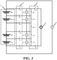
- the second switching circuit comprises 2n second switching units A 0 -A 2n-1 ; and the two ends of each of the n low-voltage measurement modules V 1 -V n are connected at the two ends of the reference voltage source 4 via the second switching units.
- the control module can specifically connect the series loop of the low-voltage measurement modules V 1 -V n and the reference voltage source 4 by turning the second switching units on, so that the output voltage of the reference voltage source 4 can be measured by the low-voltage measurement modules V 1 -V n , and then the low-voltage measurement modules V 1 -V n can be calibrated by comparing the measured voltages of the low-voltage measurement modules V 1 -V n with the output voltage of the reference voltage source 4, so as to improve the accuracy of measurement of the battery voltage by the voltage measurement circuit.
- control module can connect the series loop of the low-voltage measurement module V 1 and the reference voltage source 4 by turning on A 0 and A 1 ; and the control module can also connect the series loop of the low-voltage measurement module V 2 and the reference voltage source 4 by turning on A 2 and A 3 .
- control module can simultaneously connect the series loops of the low-voltage measurement modules V 1 -V n and the reference voltage source 4 by simultaneously turning on the second switching unit A 0 -A 2n-1 , and thus the low-voltage measurement modules V 1 -V n can simultaneously measure the voltage across of the reference voltage source 4, that is, the low-voltage measurement modules can measure the voltage across the reference voltage source 4 in parallel.
- the above embodiment provides another circuit structure of the second switching circuit that eliminates the need to turn on all the second switching units except A 1 -A n in sequence to connect the series loop of the low-voltage measurement modules V 1 -V n and the reference voltage source when turning on A 0 and A n+1 as in the corresponding embodiment of Fig. 1 .
- the low-voltage measurement modules V 1 -V n can measure the voltage across the reference voltage source simultaneously, thus reducing the time to acquire the error value corresponding to each low-voltage measurement module.
- the control module is used for controlling the switching units in the second switching circuit 3, so as to control the switching units in the first switching circuit 2 in the case where the low-voltage measurement modules V 1 -V n are all disconnected from the reference voltage source 4, and to obtain voltages U 1 , U 2 , ..., and U n of the corresponding battery cells C 1 -C n through measurement by the low-voltage measurement modules V 1 -V n ;
- the control module is further used for controlling the switching units in the first switching circuit 2, so as to control the switching units in the second switching circuit 3 in the case where the low-voltage measurement modules V 1 -V n are all disconnected from the battery cells C 1 -C n , and to obtain voltages V 1 , V 2 , ..., and V n output by the reference voltage source 4 through measurement by the low-voltage measurement modules V 1 -V n , respectively; and the control module is further used for calculating differences between V 1 , V 2
- the circuit of Fig. 1 is illustrated as an example.
- the control module records the measured values U 1 , U 2 , ..., and U n of the low-voltage measurement modules V 1 -V n when A 0 -A n+1 are turned off and S 0 -S n are turned on; the control module also turns on all the second switching units except A 1 -A n in sequence when S 0 -S n are turned off and A 0 and A n+1 are turned on so as to record the measured values V 1 , V 2 , ..., and V n across the reference voltage source 4 measured by the low-voltage measurement modules V 1 -V n , respectively, and then calculates differences between V 1 , V 2 , ..., and V n and the preset reference voltage separately to obtain errors ⁇ v1 , ⁇ v2 , ..., and ⁇ vn of the low-voltage measurement modules V 1 -V n , and calibrates U 1 , U 2 ,
- the calibration of U 1 is illustrated as an example below.
- the measurement errors ⁇ v1 , ⁇ v2 , ..., and ⁇ vn of the low-voltage measurement modules can be obtained relatively accurately, and the precision decline of the low-voltage measurement modules can be compensated by means of calibration to ensure the accuracy of measurement throughout the life cycle of the low-voltage measurement modules.
- the voltage measurement circuit further comprises a high-voltage measurement module 5, the two ends of the high-voltage measurement module 5 being connected to the two ends of the battery 1, and the control module being further connected to the high-voltage measurement module 5.
- one end of the high-voltage measurement module 5 may be connected to one end of the battery 1 via at least one switching unit, and the other end of the battery 1 is then connected to the other end of the high-voltage measurement module 5, or the two ends of the high-voltage measurement module 5 may each be connected to the two ends of the battery 1 via at least one switching unit.
- the control module is connected to the switching units and is used to control the switching units to be on or off. When the control module controls the switching units to be on, the measurement loop of the high-voltage measurement module 5 and the battery 1 is connected so as to measure the voltage across the battery 1 by the high-voltage measurement module 5.
- one of the two ends of the high-voltage measurement module 5 may be connected to one of the two ends of the battery 1 via a switching unit, and the control module is also connected to the two switching units for controlling the switching units to be on or off.
- the control module controls the two switching units to be on simultaneously, the measurement loop of the high-voltage measurement module 5 and the battery 1 is connected so as to measure the voltage across the battery 1 by the high-voltage measurement module 5.
- the high-voltage measurement module 5 is used for measuring the voltage output by the battery 1 to obtain V total ; and the control module is specifically used for using U sum as the voltage output by the battery that is obtained through measurement 1 when
- the high-voltage measurement module 5 may be a large-range voltage sensor, for example, a large-range voltmeter.
- the measurement precision of the low-voltage measurement module is 0.01V, so when the change of the measured value of the low-voltage measurement module is greater than 0.01V, the measured value recorded by the low-voltage measurement module will be changed, which may cause the measured value of the voltage of the battery 1 output by the voltage measurement circuit to keep changing up and down, thus making the output measured value not stable enough.
- the voltage V total across the battery 1 is measured directly by the high-voltage measurement module 5, and then the U sum obtained through measurement by the low-voltage measurement module and calculation is acquired, and then the voltage measured by the high-voltage measurement module 5 is compared with U sum .
- the measurement precision of the high-voltage measurement module 5 is difficult to reach the measurement precision of measuring the voltage of the battery 1, so it is necessary to calibrate the measured value of the high-voltage measurement module 5 according to U sum , specifically, using U sum as the measured value of the high-voltage measurement module 5.
- the measurement circuit in order to avoid the situation where the measured value of the battery measured by the voltage measurement circuit keeps changing due to the too high precision of the low-voltage measurement module, the measurement circuit is also provided with a high-voltage measurement module with lower accuracy for directly measuring the voltage output by the battery, and only when the absolute value of the difference between the voltage V total measured by the high-voltage measurement module and U sum is greater than the permissible error of the high-voltage measurement module, the U sum measured by the low-voltage measurement module is used as the voltage output by the battery that is obtained through measurement.
- the above embodiments can obtain the test error
- a specific implementation of the calibration of U 1 , U 2 , ..., U n is provided.
- > ⁇ allow and ⁇ vN ⁇ 0 ; calibrating U 1 , U 2 , ..., and U n according to the equation U n ' U n +
- > ⁇ allow and ⁇ vN ⁇ 0 ; and setting U n ' U n when
- the control module can calibrate U 1 , U 2 , ..., and U n when the measurement error of the low-voltage measurement module is too large, specifically when
- ; and the other is when ⁇ vN ⁇ 0, in which case it is considered that the measured value of the low-voltage measurement module is too small compared to the actual value, and at this time U 1 , U 2 , ..., and U n are calibrated by adding the difference between the measured value and the actual value, i.e., by U 1 ' U 1 +
- ⁇ allow is the smaller one of a first permissible error and a second permissible error, wherein the first permissible error is the maximum permissible error of the low-voltage measurement modules and the second permissible error is
- the set permissible error ⁇ allow of the low-voltage measurement module is specifically the maximum permissible error of the low-voltage measurement module, and the maximum permissible error of the high-voltage measurement module is assigned with the smaller one of the second permissible errors on the low-voltage measurement modules, so that when the error satisfies ⁇ allow , the error requirements of both the low-voltage measurement module and the high-voltage measurement module can definitely be satisfied.
- the technicians may also set the preset reference voltage V REF according to the practical needs.
- setting the preset reference voltage to be the average value of V 1 , V 2 , ..., and V n can make the preset reference voltage close to the interval in which the voltages of the battery cells are located, thus reducing the adjustment magnitude of each low-voltage measurement device and also reducing the time spent on adjustment.
- Embodiments of the present application provide a voltage measurement method that is based on a control module in a voltage measurement circuit of any of the above embodiments, and reference can be made to the corresponding embodiments of the voltage measurement circuit described above for the components included in the voltage measurement circuit and the connection relationship between the modules, etc.
- the voltage measurement method comprises: controlling switching units in a first switching circuit and a second switching circuit to be on or off, and acquiring voltages of battery cells that are measured by low-voltage measurement modules.
- controlling switching units in a first switching circuit and a second switching circuit to be on or off, and acquiring voltages of battery cells that are measured by low-voltage measurement modules comprises: controlling switching units in the second switching circuit, so as to control switching units in the first switching circuit in the case where the low-voltage measurement modules are all disconnected from the reference voltage source, and to obtain voltages U 1 , U 2 , ..., and U n of the corresponding battery cells through measurement by the low-voltage measurement modules; the method further comprises: controlling switching units in the first switching circuit, so as to control switching units in the second switching circuit in the case where the low-voltage measurement modules are all disconnected from the battery cells, and to obtain voltages V 1 , V 2 , ..., and V n output by the reference voltage source through measurement by the low-voltage measurement modules, respectively; calculating differences between V 1 , V 2 , ..., and V n and the preset reference voltage output by the reference voltage source separately to obtain errors ⁇ v1 , ⁇ v2 ,
- the voltage measurement circuit further comprises a high-voltage measurement module, the two ends of the high-voltage measurement module being connected to the two ends of the battery, and the control module being further connected to the high-voltage measurement module, wherein the high-voltage measurement module is used for measuring the voltage output by the battery to obtain V total ; and using U sum obtained by summing up U 1 ', U 2 ', ..., and U n ' as a voltage output by the battery that is obtained through measurement comprises: using U sum as the voltage output by the battery that is obtained through measurement when
- ⁇ ⁇ allow , U n ' U n , so that U 1 ', U 2 ', ..., and U n ' are obtained, wherein ⁇ allow is a set permissible error of the low-voltage measurement modules.
- ⁇ allow is the smaller one of a first permissible error and a second permissible error, wherein the first permissible error is the maximum permissible error of the low-voltage measurement modules and the second permissible error is
- Step 101 closing S 0 , S 1 , S 2 , ..., S n-2 , S n-1 , and S n and opening A 0 , A 1 , A 2 , ..., A n-1 , A n , and A n+1 , and measuring voltages U 1 , U 2 , ...U n-1 , and U n of battery cells C 1 , C 2 , ..., C n-1 , and C n .
- Step 103 opening S 0 , S 1 , S 2 , ..., S n-2 , S n-1 , and S n and closing A 0 , A 1 , ..., A x-1 , A x+1 , ..., A n , and A n+1 , and measuring the preset reference voltage with A x , which is denoted as V REFAx .
- closing A 0 , A 1 , ..., A x-1 , A x+1 , ..., A n and A n+1 means closing all A-numbered switches except A x ; and x ranges from 1 to n, and accordingly, V REFA1 , V REFA2 , ..., V REFAn-1 , and V REFAn can be measured.
- Step 104 calculating V REFAx -V REF to obtain the absolute errors ⁇ v1 , ⁇ v2 , ..., and ⁇ vn of the low-voltage measurement modules V 1 , V 2 , ..., V n-1 , and V n .
- ⁇ v1 , ⁇ v2 , ..., and ⁇ vn may be positive, may be negative, or may be 0.
- Step 105 setting the maximum permissible error of the measurement value V total of the high-voltage measurement module to be the absolute value
- Step 106 determining whether
- Step 107 determining whether ⁇ vn is greater than or equal to 0; if yes, proceeding to step 109; and if not, proceeding to step 110.
- , where ⁇ vn ' - ⁇ allow .
- , where ⁇ vn ' ⁇ allow .
- Step 111 obtaining U sum by summing up U 1 ', U 2 ', ..., and U n ', and obtaining the error value ⁇ n of U sum by summing up ⁇ v1 ', ⁇ v2 ', ..., and ⁇ vn .
- Step 112 determining whether
- Step 113 correcting V total to U sum , wherein
- is updated to ⁇ n and output, i.e., V' total U sum , and
- ' ⁇ n .
- Step 114 performing outputting in accordance with the actual measured value V total of the high-voltage measurement module, wherein
- remains unchanged, i.e., V' total V total , and
- '
- Embodiments of the present application provide a circuit board, comprising a voltage measurement circuit in the above mentioned implementations.
- Embodiments of the present application provide a control module which, with reference to Fig. 5 , comprises: at least one processor 201; and a memory 202 communicatively connected to the at least one processor 201, wherein the memory 202 stores instructions executable by the at least one processor 201, the instructions, when executed by the at least one processor 201, cause the at least one processor 201 to perform the voltage measurement method described above.
- the memory and the processor are connected by means of a bus, wherein the bus may comprise any number of interconnected buses and bridges, the bus connecting various circuits of the one or more processors and the memory together.
- the bus may also connect together various other circuits, such as peripherals, voltage regulators, and power management circuits, all of which are well known in the art and therefore will not be described further herein.
- a bus interface provides an interface between the bus and a transceiver.
- the transceiver may be a single element or multiple elements, such as multiple receivers and transmitters, providing a unit for communicating with various other apparatuses over a transmission medium.
- Data processed by the processor is transmitted on a wireless medium over an antenna, and further, the antenna also receives the data and conveys the data to the processor.
- the processor is responsible for bus managing and general processing, and may also provide various functions comprising timing, peripheral interface, voltage regulation, power management, and other control functions.
- the memory may be used for storing data that is used by the processor in performing operations.
Landscapes
- Physics & Mathematics (AREA)
- General Physics & Mathematics (AREA)
- Engineering & Computer Science (AREA)
- Power Engineering (AREA)
- Manufacturing & Machinery (AREA)
- Chemical & Material Sciences (AREA)
- Chemical Kinetics & Catalysis (AREA)
- Electrochemistry (AREA)
- General Chemical & Material Sciences (AREA)
- Measurement Of Current Or Voltage (AREA)
- Secondary Cells (AREA)
Applications Claiming Priority (1)
| Application Number | Priority Date | Filing Date | Title |
|---|---|---|---|
| PCT/CN2021/138783 WO2023108540A1 (fr) | 2021-12-16 | 2021-12-16 | Circuit et procédé de mesure de tension, carte de circuit imprimé et module de commande |
Publications (2)
| Publication Number | Publication Date |
|---|---|
| EP4411392A1 true EP4411392A1 (fr) | 2024-08-07 |
| EP4411392A4 EP4411392A4 (fr) | 2025-01-01 |
Family
ID=86775082
Family Applications (1)
| Application Number | Title | Priority Date | Filing Date |
|---|---|---|---|
| EP21967675.6A Pending EP4411392A4 (fr) | 2021-12-16 | 2021-12-16 | Circuit et procédé de mesure de tension, carte de circuit imprimé et module de commande |
Country Status (6)
| Country | Link |
|---|---|
| US (1) | US12360168B2 (fr) |
| EP (1) | EP4411392A4 (fr) |
| JP (1) | JP7583178B2 (fr) |
| KR (1) | KR102845799B1 (fr) |
| CN (1) | CN117157535A (fr) |
| WO (1) | WO2023108540A1 (fr) |
Families Citing this family (1)
| Publication number | Priority date | Publication date | Assignee | Title |
|---|---|---|---|---|
| JP7802530B2 (ja) * | 2021-12-28 | 2026-01-20 | 株式会社マキタ | 充電器 |
Family Cites Families (15)
| Publication number | Priority date | Publication date | Assignee | Title |
|---|---|---|---|---|
| JP2003240806A (ja) * | 2002-02-15 | 2003-08-27 | Yazaki Corp | 組電池のセル電圧測定装置及びその方法 |
| JP2005086867A (ja) * | 2003-09-05 | 2005-03-31 | Shin Kobe Electric Mach Co Ltd | 充電制御システム |
| JP4702331B2 (ja) * | 2006-10-25 | 2011-06-15 | 株式会社デンソー | 半導体集積回路装置 |
| JP5297730B2 (ja) * | 2008-09-09 | 2013-09-25 | 矢崎総業株式会社 | 電圧検出装置 |
| CN102216795B (zh) | 2008-09-18 | 2015-07-15 | 株式会社Lg化学 | 监测电池组件的电池单体的电压的装置和方法 |
| JP2010220280A (ja) * | 2009-03-13 | 2010-09-30 | Panasonic Corp | 充放電制御回路、電源装置、及び電源装置の制御方法 |
| CN101806866B (zh) * | 2010-04-07 | 2013-02-13 | 大连交通大学 | 一种燃料电池电堆的单体电池电压测量电路 |
| CN102162834A (zh) * | 2010-12-14 | 2011-08-24 | 宁波飞驰达电子科技发展有限公司 | 串联电池组中的电池电压检测装置及其方法 |
| JP2012202738A (ja) * | 2011-03-24 | 2012-10-22 | Toyota Motor Corp | 電圧測定装置、電圧測定システム、電圧測定方法 |
| JP5791584B2 (ja) * | 2012-11-28 | 2015-10-07 | 三菱重工業株式会社 | 電圧監視システム、電圧監視装置、及び電圧監視方法 |
| JP5673658B2 (ja) * | 2012-12-03 | 2015-02-18 | トヨタ自動車株式会社 | 蓄電システム |
| CN104836261A (zh) * | 2014-02-07 | 2015-08-12 | 鸿富锦精密工业(深圳)有限公司 | 电池组充电控制方法及装置 |
| CN105896665A (zh) * | 2016-05-17 | 2016-08-24 | 福建万众百源实业有限公司 | 一种新能源动力锂电池组超低功耗控制电路 |
| CN107479001B (zh) * | 2017-08-25 | 2023-04-04 | 深圳金仕盾照明科技有限公司 | 一种电池电量检测装置和灯具 |
| JP7295750B2 (ja) * | 2019-09-13 | 2023-06-21 | 矢崎総業株式会社 | 電池制御ユニットおよび電池システム |
-
2021
- 2021-12-16 EP EP21967675.6A patent/EP4411392A4/fr active Pending
- 2021-12-16 KR KR1020237026493A patent/KR102845799B1/ko active Active
- 2021-12-16 WO PCT/CN2021/138783 patent/WO2023108540A1/fr not_active Ceased
- 2021-12-16 CN CN202180097024.1A patent/CN117157535A/zh active Pending
- 2021-12-16 JP JP2023546080A patent/JP7583178B2/ja active Active
-
2023
- 2023-08-11 US US18/232,839 patent/US12360168B2/en active Active
Also Published As
| Publication number | Publication date |
|---|---|
| CN117157535A (zh) | 2023-12-01 |
| JP2024504481A (ja) | 2024-01-31 |
| KR102845799B1 (ko) | 2025-08-12 |
| EP4411392A4 (fr) | 2025-01-01 |
| WO2023108540A1 (fr) | 2023-06-22 |
| US12360168B2 (en) | 2025-07-15 |
| KR20230128359A (ko) | 2023-09-04 |
| US20230384385A1 (en) | 2023-11-30 |
| JP7583178B2 (ja) | 2024-11-13 |
Similar Documents
| Publication | Publication Date | Title |
|---|---|---|
| US12169223B2 (en) | Method and apparatus for battery SOC correction, and battery management system | |
| KR101559197B1 (ko) | 충방전 전원 교정 장치, 충방전 시험 장치, 충방전 시험 시스템 및 충방전 전원의 교정 방법 | |
| EP1806592B1 (fr) | Procédé et système destiné à surveiller des blocs de batteries | |
| KR101732854B1 (ko) | 축전지 장치 및 축전지 시스템 | |
| US10429450B2 (en) | Battery sensing method and apparatus | |
| EP3429053A1 (fr) | Dispositif et procédé de surveillance de batterie | |
| US11971770B2 (en) | Current calibration device and cureent calibration method for power supply channel in test system thereof | |
| US12360168B2 (en) | Voltage measurement circuit and method, circuit board, and control module | |
| US20250383375A1 (en) | Traceability device for direct-current (dc) high-voltage divider based on distributed synchronous measurement, and calibration method using the same | |
| US20130162259A1 (en) | Reference reuse in high voltage stack monitoring | |
| US20220367926A1 (en) | BMS and Battery System | |
| CN118393191B (zh) | 电源板卡、电源板卡的精度补偿方法和测试机 | |
| CN214473651U (zh) | Rms电源切换模块自动测试与校准系统 | |
| CN118566814B (zh) | 一种自动测试设备及电流源校准方法 | |
| WO2021180674A1 (fr) | Procédé d'étalonnage d'un capteur de courant d'un système de batterie | |
| US7554299B2 (en) | Battery monitoring circuit and method | |
| US12130320B2 (en) | Measuring device | |
| CN117347704A (zh) | 电池充放电设备电压电流自校准采样电路及方法 | |
| CN116338480A (zh) | 一种消除共模电压误差的电池电压采样系统及补偿方法 | |
| CN110133399A (zh) | 充电设备校准方法、装置、充电系统和存储介质 | |
| CN216696441U (zh) | 一种电芯通道扩展电路 | |
| CN121348155B (zh) | 电源测试电路及电源测试方法 | |
| CN113985243B (zh) | 一种高精度运算放大器测试系统校准方法及装置 | |
| CN112362957A (zh) | 采样电路和分流器 | |
| CN120468683A (zh) | 串联电池模组间校准soc的方法以及电池系统的soc估算方法 |
Legal Events
| Date | Code | Title | Description |
|---|---|---|---|
| STAA | Information on the status of an ep patent application or granted ep patent |
Free format text: STATUS: THE INTERNATIONAL PUBLICATION HAS BEEN MADE |
|
| PUAI | Public reference made under article 153(3) epc to a published international application that has entered the european phase |
Free format text: ORIGINAL CODE: 0009012 |
|
| STAA | Information on the status of an ep patent application or granted ep patent |
Free format text: STATUS: REQUEST FOR EXAMINATION WAS MADE |
|
| 17P | Request for examination filed |
Effective date: 20230817 |
|
| AK | Designated contracting states |
Kind code of ref document: A1 Designated state(s): AL AT BE BG CH CY CZ DE DK EE ES FI FR GB GR HR HU IE IS IT LI LT LU LV MC MK MT NL NO PL PT RO RS SE SI SK SM TR |
|
| RAP1 | Party data changed (applicant data changed or rights of an application transferred) |
Owner name: CONTEMPORARY AMPEREX TECHNOLOGY(HONG KONG) LIMITED |
|
| A4 | Supplementary search report drawn up and despatched |
Effective date: 20241129 |
|
| RIC1 | Information provided on ipc code assigned before grant |
Ipc: G01R 31/3835 20190101ALI20241125BHEP Ipc: G01R 31/396 20190101ALI20241125BHEP Ipc: H01M 10/48 20060101ALI20241125BHEP Ipc: G01R 31/36 20200101ALI20241125BHEP Ipc: G01R 19/00 20060101AFI20241125BHEP |
|
| DAV | Request for validation of the european patent (deleted) | ||
| DAX | Request for extension of the european patent (deleted) |