EP4411437A1 - Fibre optique avec performance améliorée de macro-courbure et de micro-courbure - Google Patents
Fibre optique avec performance améliorée de macro-courbure et de micro-courbure Download PDFInfo
- Publication number
- EP4411437A1 EP4411437A1 EP23181466.6A EP23181466A EP4411437A1 EP 4411437 A1 EP4411437 A1 EP 4411437A1 EP 23181466 A EP23181466 A EP 23181466A EP 4411437 A1 EP4411437 A1 EP 4411437A1
- Authority
- EP
- European Patent Office
- Prior art keywords
- cladding
- optical fiber
- core
- range
- dopant
- Prior art date
- Legal status (The legal status is an assumption and is not a legal conclusion. Google has not performed a legal analysis and makes no representation as to the accuracy of the status listed.)
- Withdrawn
Links
Images




Classifications
-
- G—PHYSICS
- G02—OPTICS
- G02B—OPTICAL ELEMENTS, SYSTEMS OR APPARATUS
- G02B6/00—Light guides; Structural details of arrangements comprising light guides and other optical elements, e.g. couplings
- G02B6/02—Optical fibres with cladding with or without a coating
- G02B6/036—Optical fibres with cladding with or without a coating core or cladding comprising multiple layers
- G02B6/03616—Optical fibres characterised both by the number of different refractive index layers around the central core segment, i.e. around the innermost high index core layer, and their relative refractive index difference
- G02B6/03638—Optical fibres characterised both by the number of different refractive index layers around the central core segment, i.e. around the innermost high index core layer, and their relative refractive index difference having 3 layers only
- G02B6/0365—Optical fibres characterised both by the number of different refractive index layers around the central core segment, i.e. around the innermost high index core layer, and their relative refractive index difference having 3 layers only arranged - - +
Definitions
- Embodiments of the present disclosure relate to the field of optical fiber communications, and more particularly to a reduced diameter optical fiber with improved macrobending and microbending performance usable for an optical fiber communication system.
- optical fibers with small diameters are attracting attention as optical fibers that realize dense optical fiber cables.
- An optical fiber with a small diameter is in general an optical fiber in which a portion made of glass has a small diameter and the cladding diameter is small.
- optical fibers with small diameters also include one whose outer circumference with a coating, formed such that the coating covers the outer circumference of a cladding, included is small because the cladding diameter is small.
- optical fibers with small diameters are attracting attention as optical fibers that realize dense optical fiber cables.
- An optical fiber with a small diameter is in general an optical fiber in which a portion made of glass has a small diameter and the cladding diameter is small.
- optical fibers with small diameters also include one whose outer circumference with a coating, formed such that the coating covers the outer circumference of a cladding, included is small because the cladding diameter is small.
- Optical fiber cables are a critical component of a modern communications network across the globe. As the data and data rate requirement increases, more optical fibers are required in the network to support higher capacity and speed. Data centers are continuously trying to meet the challenges of delivering more bandwidth networks. However, attributes such as attenuation and bend loss are a few significant factors aiding the degradation of signals and channel capacity.
- One way to improve the channel capacity is to increase the number of optical fibers in the network, which can be done by reducing the diameter of the optical fibers.
- attributes like micro-bending sensitivity, attenuation, and residual and applied stress may increase.
- a fiber clad diameter can be reduced by changing glass material composition of the optical fibers.
- a prior art reference “ US8200057B2” discloses an optical fiber with a core, an inner cladding, and an outer cladding.
- the inner cladding surrounds the core, and an outer cladding with a deep trench surrounds the inner cladding.
- the fiber with both core and inner cladding is doped with an up-dopant (Germanium) and a down-dopant (Fluorine).
- the outer cladding deep trench is doped with fluorine material.
- both the core and the inner cladding are doped with Germanium, the fiber results more density fluctuations in the core and the inner cladding, an increased Rayleigh scattering which leads to high attenuation losses. Since both the core and inner cladding are doped with Germanium, the usage of Germanium is high which is not cost-effective way to manufacture the fiber and it also leads to an increased viscosity mismatch in the cladding interfaces of fiber.
- US10094975B2 describes an optical fiber having a core doped with the up dopant such as chlorine.
- An inner cladding surrounds the core that is doped with down-dopant such as fluorine and an outer cladding surrounds the inner cladding that is down-doped with fluorine.
- the viscosity of inner cladding is increased and hence viscosity mismatch also increase, which further increases the structural relaxation time during fiber draw process leads to increase in scattering losses and attenuation losses in the optical fiber.
- US11125937B2 describes an optical fiber that has a core that is doped with Germanium, an inner cladding surrounding the core, and an outer cladding surrounding the inner cladding.
- the outer cladding is chlorine-doped such that the relative refractive index varies as a function of radius.
- the radially varying relative refractive index profile of the outer cladding reduces excess stress in the core and inner cladding, which helps lower fiber attenuation while also reducing macro bend and micro bend loss.
- the outer cladding of the optical fiber is chlorine-doped, the outer glass of the optical fiber become less viscous and soft which leads to increased draw tension in the core during the optical fiber draw process.
- the increased draw tension in the core is not desirable as this increase density fluctuations and scattering losses in the optical fiber.
- the present disclosure provides a reduced diameter optical fiber with improved macro-bending and micro-bending performance.
- an optical fiber comprising one or more cores extending along a central axis of the optical fiber and a cladding surrounding the one or more core.
- the one or more core comprises at least a first up-dopant and a second up-dopant.
- the cladding has at least the second up-dopant, at least one down-dopant, and an undoped region.
- the optical fiber has (i) an attenuation less than 0.324 dB/km at 1310 nm wavelength and less than 0.19 dB/km at 1550 nm wavelength, and (ii) a MAC number less than 6.8.
- the cladding comprises a first cladding surrounding the one or more core , a second cladding surrounding the first cladding , and a third cladding surrounding the second cladding.
- the first cladding has at least the second up-dopant
- the second cladding has at least one down-dopant
- the third cladding is undoped.
- the first cladding has traces of the first up-dopant and the at least one down-dopant
- the third cladding has traces of the at least one down-dopant.
- the first up-dopant is Germanium (Ge)
- the second up-dopant is Chlorine (Cl)
- at least one down-dopant is Fluorine (F).
- the optical fiber has
- the core is defined by a core refractive index ⁇ 1
- the first cladding is defined by a first cladding refractive index ⁇ 2
- the second cladding is defined by a second cladding refractive index ⁇ 3
- the third cladding is defined by a third cladding refractive index ⁇ 4 such that ⁇ 1 > ⁇ 2 > ⁇ 3 and ⁇ 3 ⁇ ⁇ 4.
- the optical fiber has a clad diameter between 79.3 ⁇ m and 125.7 ⁇ m. Further, an absolute difference between absolute value of a first cladding refractive index percentage ⁇ 2% and a second cladding refractive index percentage ⁇ 3% is in a range of 0.26 to 0.30.
- the core is defined by a core thickness T1 in a range of 3.6 to 4.1 ⁇ m
- the first cladding is defined by a first cladding thickness T2 in a range of 5.4 to 5.8 ⁇ m
- the second cladding is defined by a second cladding thickness T3 in a range of 6 to 7 ⁇ m
- the third cladding is defined by a third cladding thickness T4 in range of 23 to 45.6 such that T2 is greater than T1 and less than T3.
- the core is defined by a core radius R1 in a range of 3.6 to 4.1 ⁇ m
- the first cladding is defined by a first cladding radius R2 in a range of 9 to 10 ⁇ m
- the second cladding is defined by a second cladding radius R3 in a range of 15 to 16 ⁇ m
- the third cladding is defined by a third cladding radius R4 in a range of 39.5 to 63 ⁇ m such that a final clad diameter of the optical fiber is in a range of 79 to 126 ⁇ m .
- the third cladding is covered by a first coating followed by a second coating , wherein the first coating is defined by a first coating thickness in a range of 15 to 43.5 ⁇ m and the second coating is defined by a second coating thickness in a range of 9 to 42.5 ⁇ m, wherein the second coating is a coloured coating.
- the optical fiber has a ratio of the first coating thickness to the second coating thickness in a range of 0.5 and 3.
- a novel refractive index (RI) profile of an optical fiber with an immediate fluorine trench surrounding an up-doped inner clad and an up-doped core region.
- the inner clad is doped with chlorine surrounding the up-doped core region and the core region is doped with germanium and chlorine.
- the enhanced design of the RI profile of the optical fiber reduces macro-bending and micro-bending sensitivity.
- An optical fiber refers to a medium associated with transmission of information over long distances in the form of light pulses.
- the optical fiber uses light to transmit voice and data communications over long distances when encapsulated in a jacket/sheath.
- the optical fiber may be of ITU.T G.657.A2 category.
- the optical fiber may be of ITU.T G.657.A1 or G.657.B3 or G.652.D or other suitable category or the optical fiber may be a multi-core optical fiber.
- the ITU.T stands for International Telecommunication Union-Telecommunication Standardization Sector, is one of the three sectors of the ITU.
- the ITU is the United Nations specialized agency in the field of telecommunications and is responsible for studying technical, operating and tariff questions and issuing recommendations on them with a view to standardizing telecommunications on a worldwide basis.
- the optical fiber may be a bend insensitive fiber that has less degradation in optical properties or less increment in optical attenuation during multiple winding/unwinding operations of an optical fiber cable.
- the optical fiber comprises one or more cores, one or more clads or claddings and/or one or more coating layers, where a core is a light-carrying portion of the optical fiber using total internal reflection in which optical signal is confined and a cladding is a region that prevents loss of signal by preventing any signal leakage from the core.
- the refractive index of the cladding is lower than the refractive index of core in order to cause reflection within the core so that light waves are transmitted through the optical fiber.
- the coating protects the optical fiber from moisture and physical damage and also improves the strength in terms of heat and cold resistance.
- the refractive index profile of the optical fiber as used herein is referred to as the distribution of refractive indexes in the optical fiber from the core to the outmost cladding layer of the optical fiber.
- the optical fiber may be configured as a step index fiber.
- the refractive index of the core of the optical fiber is constant throughout the fiber and is higher than the refractive index of the cladding.
- the optical fiber may be configured as a graded index fiber, wherein the refractive index of the core gradually varies as a function of the radial distance from the center of the core.
- Term “viscosity” is the measure of resistance to flow.
- Term "core" of the optical fiber (100) as used herein is referred to as an inner most cylindrical structure present in the center of the optical fiber (100), that is configured to guide the light rays inside the optical fiber (100).
- the core (102) may be a glass core.
- up-doping is referred to as adding doping materials to facilitate increase in the refractive index of a particular layer or part of the optical fiber.
- the materials configured to facilitate up-doping are known as up-dopants.
- down-doping is referred to as adding doping materials to facilitate the decrease in the refractive index of a particular layer or part of the optical fiber.
- the materials configured to facilitate down-doping are known as down-dopants.
- Term “cladding" of the optical fiber (100) as used herein is referred to as one or more layered structure covering the core (102) of the optical fiber (100) from the outside, that is configured to possess a lower refractive index than the refractive index of the core (102) to facilitate total internal reflection of light rays inside the optical fiber (100).
- Term coating thickness ratio is defined as a ratio of the first coating thickness to the second coating thickness.
- Fig. 1 is a pictorial snapshot illustrating a cross-sectional view of an optical fiber in accordance with an embodiment of the present disclosure .
- Fig. 2 is an exemplary refractive index (RI) profile of the optical fiber in accordance with an embodiment of the present disclosure .
- the optical fiber (100) comprises a core (102) extending along a central axis (112) of the optical fiber (100).
- the core (102) further comprises at least a first up-dopant and a second up-dopant.
- the first up-dopant may be germanium, for example and the second up-dopant may be chlorine.
- Addition of germanium increases the refractive index in the core (102).
- germanium may be present in a range of 2500 to 3200 ppm, preferably 3000 ppm and chlorine may be present in a range of 1850 to 2100 ppm in the core (102).
- germanium is present in a range of 3.5 to 4.5% (mol%), preferably 4% (mol%).
- the core (102) is defined by a core radius R1 and a core refractive index ⁇ 1.
- the core radius R1 is in a range of 3.6 to 4.1 ⁇ m and the core refractive index ⁇ 1 is in a range of 4.9 to 5.5.
- ⁇ 1% is in a range of 0.34 to 0.38.
- the core (102) is further defined by a core thickness T1 in a range of 3.6 to 4.1 ⁇ m.
- the optical fiber (100) further comprises a cladding (104) surrounding the core (102).
- the cladding (104) further comprises a first cladding (106) surrounding the core (102), a second cladding (108) surrounding the first cladding (106), and a third cladding (110) surrounding the second cladding (108).
- the first cladding (106) comprises of silica glass doped with the second up-dopant
- the second cladding (108) has at least one down-dopant
- the third cladding (110) is undoped.
- the first cladding (106) is up-doped with chlorine
- the second cladding (108) is down-doped with fluorine, for example, forming an immediate trench to the first cladding (106)
- the third cladding (110) is pure silica.
- a trench is referred as a down doped region with a higher down dopant concentration to decrease the refractive index of the down doped region with respect to pure silica and increase the relative refractive index of the core region.
- the undoped means a region of the optical fiber contains a dopant not intentionally added to the region during fabrication, but the term does not exclude low levels of background doping that may be inherently incorporated during the fabrication process. Such background doping levels are very low in amount that does not have an insignificant effect on the refractive index of the undoped region.
- chlorine may be present in a range of 2490 to 2800 ppm, preferably 2680 ppm in the first cladding (106). and fluorine may be present in a range of 0.8 to 1% (mol%) in the second cladding (108). If chlorine and fluorine are doped beyond the given range, bubbles may be formed in the cladding (104) and below the given range, viscosity matching at the core-cladding interface may be impacted.
- first cladding (106) may have traces of the first up-dopant and the at least one down-dopant
- second cladding (108) may have traces of the second up-dopant
- third cladding (110) may have traces of the at least one down-dopant.
- the first cladding (106) may have traces of the first up-dopant in 7.1% to 16.1% region of a total region of the first cladding (106) and the traces of at least one down-dopant in 8.9% to 17.9% region of the total region of the first cladding (106).
- the third cladding (110) may have traces of the at least one down-dopant in 1.1% to 4.3% region of a total region of the third cladding (110).
- the third cladding (110) when the diameter of the cladding (104) of the optical fiber (100) is equal to 80 ⁇ 0.7, the third cladding (110) may have traces of the at least one down-dopant in 2.1% to 4.3% region of the total region of the third cladding (110). And when the diameter of the cladding (104) of the optical fiber (100) is equal to 125 ⁇ 0.7, the third cladding (110) may have traces of the at least one down-dopant in 1.1% to 2.2% region of the total region of the third cladding (110).
- the traces of dopants may be induced in another region through the diffusion process during Outside Vapor Deposition (OVD) process.
- OTD Outside Vapor Deposition
- the up-doping in the aforesaid ranges, reduces the viscosity mismatch between the core (102) and the first cladding (106) i.e., the core-cladding interface and also helps in reducing viscosity mismatch between the first cladding (106) and the second cladding (108), which further reduces structural relaxation time during fiber draw and hence scattering and attenuation losses.
- the concentration of the first up-dopant in the core (102), the concentration of the second up-dopant in the first cladding (106) and the concentration of the down-dopant in the second cladding (108) is used to match the viscosity. Mismatch of the viscosity in the optical fiber leads to displacement of the core (102) to the first cladding (106) at a given temperature, such as temperatures between the softening points of the core (102) to the first cladding (106) and the displacement causes interfacial fluctuations that become permanent when the glass is cooled and, thereby, increases attenuation. Matching the viscosity of the core (102), the first cladding (106) and the second cladding (108) reduces interfacial fluctuation.
- the addition of chlorine in the first cladding (106) reduces residual stress between the core (102) and the first cladding (106).
- the residual stress is a stress that develops over the entire length from thermal expansion mismatch between the core (102) and the first cladding (106) as well as draw induced stress.
- down-doping with fluorine in the second cladding (108) reduces RI as well as viscosity and creates trench which helps in increasing mode confinement (i.e., leaking loss due to bending and stress) and hence reduces macro-bending and micro-bending losses, which is very critical as bend loss sensitivity increase as we move towards lower diameter optical fibers i.e., ⁇ 125 ⁇ m.
- the bending loss in an optical fiber under pressure is related linearly to the resulting lateral pressure, and the pressure on the core can be minimized by providing a cushion in the core region, which is done by coating thickness changes and providing a trench between the core and an outer cladding of the optical fiber.
- the trench protects the core from deformation.
- the combination of both up-doping and down-doping helps in reducing viscosity mismatch between the core (102), the first cladding (106), the second cladding (108) and the third cladding (110), which provides benefit in attenuation, macro-bend, and micro-bend losses in lower-diameter optical fibers.
- the aforesaid combination also reduces losses due to applied stress that is imparted to the optical fiber (100) by bending, pulling or twisting during processing, handling and deployment.
- the aforesaid ranges of radius, thickness and refractive index are important to achieve the characteristics and properties of the optical fiber (100) of the present disclosure.
- the first cladding (106) is defined by a first cladding radius R2 and a first cladding refractive index ⁇ 2
- the second cladding (108) is defined by a second cladding radius R3 and a second cladding refractive index ⁇ 3
- the third cladding (110) is defined by a third cladding radius R4 and a third cladding refractive index ⁇ 4 such that ⁇ 1 > ⁇ 2 > ⁇ 3 and ⁇ 3 ⁇ ⁇ 4.
- Table 2 is a tabular representation illustrating peak and average values of ⁇ 1, ⁇ 2, ⁇ 3 with reference to a horizontal axis (202) representing pure silica: Table 2 Peak Avg. ⁇ 1 5.5 5.1 ⁇ 2 0.04 0.025 ⁇ 3 -5.3 -4.4
- the first cladding radius R2 is in a range of 9 to 10 ⁇ m
- the second cladding radius R3 is in a range of 15 to 16 ⁇ m
- the third cladding radius R4 is in a range of 39 to 40 ⁇ m such that a final clad diameter of the optical fiber (100) is in a range of 80 to 125 ⁇ m with a tolerance of ⁇ 0.7 ⁇ m.
- the first cladding refractive index ⁇ 2 is in a range of 0.2 to 0.4
- the second cladding refractive index ⁇ 3 is in a range of -3.9 to -5.3
- the third cladding refractive index ⁇ 4 is in a range of 0 to 0.02.
- ⁇ 2% is in a range of 0.02 to 0.04
- ⁇ 3% is in a range of -0.27 to -0.34
- ⁇ 4% is in a range of 0 to 0.002.
- an absolute difference between absolute value of a first cladding refractive index percentage ⁇ 2% and a second cladding refractive index percentage ⁇ 3% may be in a range of 0.26 to 0.30.
- the first cladding (106) is further defined by a first cladding thickness T2
- the second cladding (108) is further defined by a second cladding thickness T3
- the third cladding (110) is further defined by a third cladding thickness T4.
- the first cladding thickness T2 is in a range of 5.4 to 5.8 ⁇ m
- the second cladding thickness T3 is in a range of 6 to 7 ⁇ m
- the third cladding thickness T4 is in range of 23 to 45.6 ⁇ m such that T2 is greater than T1 and less than T3.
- the cladding (104) has a diameter (i.e., clad diameter) between 79.3 ⁇ m and 125.7 ⁇ m.
- the cladding (104) of the optical fiber (100) may have a diameter that is equal to 80 ⁇ 0.7 ⁇ m such that the third cladding thickness T4 is in range of 23 to 24 ⁇ m.
- the aforesaid ranges of radius, thickness and refractive index are important to achieve the characteristics and properties of the optical fiber (100) of the present disclosure.
- Fig. 3 is a snapshot illustrating concentration profiles of a core, in accordance with an embodiment of the present disclosure .
- Different concentration profiles (300) of the core (102) include the first cladding (aka “inner cladding”) (106), the second cladding (aka “outer cladding with a trench”) (108) and the third cladding (aka “outer cladding undoped”) (110).
- Fig. 4 illustrates a graph (400) showing variation of concentration of dopants in the RI profile (300) including diffusion.
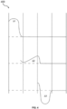
- Fig. 5 is the RI profile (500) with an up-doped first cladding.
- Fig. 6 is the RI profile (600) with a down-doped second cladding in accordance with embodiments of the present disclosure.
- Fig. 7 is a snapshot illustrating a cross-sectional view of an optical fiber having coating.
- Fig. 8 is a snapshot illustrating a cross-sectional view of an optical fiber having multiple cores in accordance with an embodiment of the present disclosure .
- the optical fiber (100) may have coatings, where the third cladding (110) is covered by a first coating (114) followed by a second coating (116).
- the first coating (114) is a protective primary coating around the third cladding (110) acting as a soft layer and the second coating is a protective secondary coating around the primary coating acting as a hard layer.
- the first coating (114) is defined by a first coating thickness having a range of 15 to 43.5 ⁇ m and the second coating (116) is defined by a second coating thickness having a range of 9 to 42.5 ⁇ m.
- the second coating (116) may be a coloured coating.
- a coating thickness ratio may be in a range of 0.5 and 3.
- the optical fiber (100) has a coating diameter of about 158 ⁇ m to 250 ⁇ m.
- the cladding (104) of the optical fiber (100) may have a diameter that is equal to 80 ⁇ 0.7 ⁇ m such that the first coating thickness may be in a range of 15 to 30 ⁇ m and the second coating thickness may be in a range of 9 to 20 ⁇ m.
- the cladding (104) of the optical fiber (100) may have a diameter that is equal to 125 ⁇ 0.7 ⁇ m such that the first coating thickness may be in a range of 20 to 43.5 ⁇ m and the second coating thickness may be in a range of 19 to 42.5 ⁇ m.
- the optical fiber (100) may have a plurality of cores (102) of which first through fourth cores (102a-102d) are shown in Fig. 8 .
- the plurality of cores (102) may be a glass core.
- the plurality of cores (102) comprises at least a first up-dopant and a second up-dopant.
- the optical fiber (100) comprising the plurality of cores (102) may be termed as a multi-core optical fiber that includes multiple core regions, each capable of communicating the optical signals between transceivers including transmitters and receivers which may allow for parallel processing of multiple optical signals.
- the plurality of cores (102) may be arranged in a predefined lattice on the cross-section of the optical fiber (100) that is perpendicular to an axis extending parallelly along the central axis (112) of the optical fiber (100).
- the predefined lattice is a square lattice.
- the predefined lattice may be a hexagonal lattice. It will be apparent to a person skilled in the art that the plurality of cores (102) are shown to be arranged in the square lattice to make the illustrations concise and clear and should not be considered as a limitation of the present disclosure.
- each core of the plurality of cores (102) may have a core radius.
- the core radius is measured from a central axis of the core (not shown).
- the first through fourth cores (102a-102d) may have the core radius.
- the core radius of each core of the plurality of cores (102) may be equal.
- the core radius of each core of the plurality of cores (102) may be different.
- the optical fiber (100) further comprises a cladding (104) surrounding the plurality of cores (102).
- the cladding (104) comprises a first cladding (106) surrounding the core (102), a second cladding (108) surrounding the first cladding (106), and a third cladding (110) surrounding the second cladding (108).
- the first cladding (106) comprises silica glass doped with the second up-dopant
- the second cladding (108) has at least one down-dopant
- the third cladding (110) is undoped.
- the first cladding (106) is up-doped with chlorine
- the second cladding (108) is down-doped with fluorine, for example, forming an immediate trench adjacent to the first cladding (106)
- the third cladding (110) is pure silica.
- the cladding (104) of the optical fiber (100) may have a cladding diameter D less than or equal to 125 ⁇ 0.7 ⁇ m.
- the optical fiber (100) has low attenuation and low macro bending loss and micro bending loss.
- the attenuation measures the amount of light/signal lost between input and output.
- the micro bending loss refers to small-scale "bends" in the optical fiber, often from pressure exerted on the optical fiber itself as when it is cabled and the other elements in the cable press on it and the macro bending loss refers to a loss caused by bending the optical fiber at a predetermined curvature.
- the optical fiber (100) has an attenuation less than 0.324 dB/km at 1310 nm wavelength and less than 0.19 dB/km at 1550 nm wavelength.
- the optical fiber (100) has a macro bend loss of 0.02 dB at 1 turn, 10 mm bend radius and 1550 nm wavelength, 0.07 dB at 1 turn, 10 mm bend radius and 1625 nm wavelength, 0.01 dB at 10 turns, 15 mm bend radius and 1550 nm wavelength and 0.09 dB at 10 turns, 15 mm bend radius and 1625 nm wavelength. Furthermore, the optical fiber (100) has a micro bending loss of 1.08 dB/km at 1550 nm wavelength and 1.379 dB/km at 1625 nm wavelength.
- the optical fiber (100) when the diameter of the cladding (104) of the optical fiber (100) is equal to 125 ⁇ 0.7 ⁇ m, the optical fiber (100) has a micro bending loss of 0.3 dB/km at 1550 nm wavelength and 0.35 dB/km at 1625 nm wavelength
- the optical fiber (100) has a MAC number less than 6.8.
- the MAC number refers to mode field diameter (MFD) divided by cut-off wavelength, wherein the mode field diameter describes the distribution of light intensity observed at the cross-section of a single-mode optical fiber and the cut-off wavelength is defined as a wavelength above which a single-mode fiber will support and propagate only one mode of light.
- MFD mode field diameter
- the present disclosure proposes a reduced diameter optical fiber with improved macrobending and microbending performance with low attenuation losses.
Landscapes
- Physics & Mathematics (AREA)
- General Physics & Mathematics (AREA)
- Optics & Photonics (AREA)
- Glass Compositions (AREA)
Applications Claiming Priority (1)
| Application Number | Priority Date | Filing Date | Title |
|---|---|---|---|
| IN202311007321 | 2023-02-06 |
Publications (1)
| Publication Number | Publication Date |
|---|---|
| EP4411437A1 true EP4411437A1 (fr) | 2024-08-07 |
Family
ID=87047750
Family Applications (1)
| Application Number | Title | Priority Date | Filing Date |
|---|---|---|---|
| EP23181466.6A Withdrawn EP4411437A1 (fr) | 2023-02-06 | 2023-06-26 | Fibre optique avec performance améliorée de macro-courbure et de micro-courbure |
Country Status (2)
| Country | Link |
|---|---|
| US (1) | US20240264367A1 (fr) |
| EP (1) | EP4411437A1 (fr) |
Citations (4)
| Publication number | Priority date | Publication date | Assignee | Title |
|---|---|---|---|---|
| US8200057B2 (en) | 2009-06-26 | 2012-06-12 | Yangtze Optical Fibre And Cable Company, Ltd. | Single-mode fiber and production method thereof |
| US20160139333A1 (en) * | 2012-01-10 | 2016-05-19 | Yangtze Optical Fibre And Cable Joint Stock Limited Company | Bending insensitive single-mode optical fiber |
| US10094975B2 (en) | 2016-07-29 | 2018-10-09 | Corning Incorporated | Low loss single mode fiber with chlorine doped core |
| US11125937B2 (en) | 2016-09-21 | 2021-09-21 | Corning Incorporated | Optical fibers having a varying clad index and methods of forming same |
-
2023
- 2023-06-25 US US18/340,867 patent/US20240264367A1/en active Pending
- 2023-06-26 EP EP23181466.6A patent/EP4411437A1/fr not_active Withdrawn
Patent Citations (4)
| Publication number | Priority date | Publication date | Assignee | Title |
|---|---|---|---|---|
| US8200057B2 (en) | 2009-06-26 | 2012-06-12 | Yangtze Optical Fibre And Cable Company, Ltd. | Single-mode fiber and production method thereof |
| US20160139333A1 (en) * | 2012-01-10 | 2016-05-19 | Yangtze Optical Fibre And Cable Joint Stock Limited Company | Bending insensitive single-mode optical fiber |
| US10094975B2 (en) | 2016-07-29 | 2018-10-09 | Corning Incorporated | Low loss single mode fiber with chlorine doped core |
| US11125937B2 (en) | 2016-09-21 | 2021-09-21 | Corning Incorporated | Optical fibers having a varying clad index and methods of forming same |
Also Published As
| Publication number | Publication date |
|---|---|
| US20240264367A1 (en) | 2024-08-08 |
Similar Documents
| Publication | Publication Date | Title |
|---|---|---|
| EP1929345B1 (fr) | Fibre optique a faible perte par courbure | |
| EP3465298B1 (fr) | Câble à fibres optiques à haute densité de fibres et à faible perte de courbure | |
| US8849082B2 (en) | Low bend loss optical fiber | |
| EP2539752B1 (fr) | Fibre optique à faibles pertes par courbures | |
| WO2018022411A1 (fr) | Fibre monomodale à faible perte avec coeur dopé au chlore | |
| EP3173831A1 (fr) | Fibre optique | |
| US11573368B2 (en) | Universal optical fibre with double trench | |
| US12578525B2 (en) | Optical fiber with inverse triangular trench design | |
| US11714227B2 (en) | Universal optical fiber | |
| EP4411437A1 (fr) | Fibre optique avec performance améliorée de macro-courbure et de micro-courbure | |
| EP4206763A1 (fr) | Fibre optique multicoeur | |
| EP3933467B1 (fr) | Fibre optique | |
| EP3865920A1 (fr) | Fibre optique dotée d'un profil de noyau de ligne centrale | |
| EP4394462A1 (fr) | Fibre optique à gaine de fluor adjacente au coeur | |
| EP4418024A1 (fr) | Fibre optique à grande surface effective | |
| EP4485023A1 (fr) | Fibre optique et câble à fibre optique | |
| US12504578B2 (en) | Multicore optical fiber and multicore optical fiber cable | |
| EP4254026A1 (fr) | Fibre optique avec profil d'indice de réfraction (ri) à réduction d'atténuation | |
| EP4254028A1 (fr) | Fibre optique monomode adaptée à des applications en ruban | |
| EP4485022A1 (fr) | Câble à fibre optique et fibre optique à diamètre réduit | |
| EP4517398A1 (fr) | Fibre optique et ruban de fibre optique | |
| US12353002B2 (en) | Optical fiber with improved microbending performance | |
| US20260043961A1 (en) | Optical Fiber Cable and Optical Fiber with Reduced Diameter | |
| EP4485021A2 (fr) | Câble à fibre optique et fibre optique à double tranchée | |
| US20250180841A1 (en) | Optical fiber having thin coating diameter without increased microbend sensitivity |
Legal Events
| Date | Code | Title | Description |
|---|---|---|---|
| PUAI | Public reference made under article 153(3) epc to a published international application that has entered the european phase |
Free format text: ORIGINAL CODE: 0009012 |
|
| STAA | Information on the status of an ep patent application or granted ep patent |
Free format text: STATUS: THE APPLICATION HAS BEEN PUBLISHED |
|
| AK | Designated contracting states |
Kind code of ref document: A1 Designated state(s): AL AT BE BG CH CY CZ DE DK EE ES FI FR GB GR HR HU IE IS IT LI LT LU LV MC ME MK MT NL NO PL PT RO RS SE SI SK SM TR |
|
| STAA | Information on the status of an ep patent application or granted ep patent |
Free format text: STATUS: THE APPLICATION IS DEEMED TO BE WITHDRAWN |
|
| 18D | Application deemed to be withdrawn |
Effective date: 20250208 |