EP4411691A1 - Procédé de commande de conduite et dispositif de commande de conduite - Google Patents
Procédé de commande de conduite et dispositif de commande de conduite Download PDFInfo
- Publication number
- EP4411691A1 EP4411691A1 EP21958594.0A EP21958594A EP4411691A1 EP 4411691 A1 EP4411691 A1 EP 4411691A1 EP 21958594 A EP21958594 A EP 21958594A EP 4411691 A1 EP4411691 A1 EP 4411691A1
- Authority
- EP
- European Patent Office
- Prior art keywords
- deceleration rate
- switching
- deceleration
- host vehicle
- vehicle speed
- Prior art date
- Legal status (The legal status is an assumption and is not a legal conclusion. Google has not performed a legal analysis and makes no representation as to the accuracy of the status listed.)
- Withdrawn
Links
Images




Classifications
-
- G—PHYSICS
- G08—SIGNALLING
- G08G—TRAFFIC CONTROL SYSTEMS
- G08G1/00—Traffic control systems for road vehicles
- G08G1/16—Anti-collision systems
-
- B—PERFORMING OPERATIONS; TRANSPORTING
- B60—VEHICLES IN GENERAL
- B60W—CONJOINT CONTROL OF VEHICLE SUB-UNITS OF DIFFERENT TYPE OR DIFFERENT FUNCTION; CONTROL SYSTEMS SPECIALLY ADAPTED FOR HYBRID VEHICLES; ROAD VEHICLE DRIVE CONTROL SYSTEMS FOR PURPOSES NOT RELATED TO THE CONTROL OF A PARTICULAR SUB-UNIT
- B60W30/00—Purposes of road vehicle drive control systems not related to the control of a particular sub-unit, e.g. of systems using conjoint control of vehicle sub-units
- B60W30/14—Adaptive cruise control
- B60W30/143—Speed control
- B60W30/146—Speed limiting
-
- B—PERFORMING OPERATIONS; TRANSPORTING
- B60—VEHICLES IN GENERAL
- B60W—CONJOINT CONTROL OF VEHICLE SUB-UNITS OF DIFFERENT TYPE OR DIFFERENT FUNCTION; CONTROL SYSTEMS SPECIALLY ADAPTED FOR HYBRID VEHICLES; ROAD VEHICLE DRIVE CONTROL SYSTEMS FOR PURPOSES NOT RELATED TO THE CONTROL OF A PARTICULAR SUB-UNIT
- B60W30/00—Purposes of road vehicle drive control systems not related to the control of a particular sub-unit, e.g. of systems using conjoint control of vehicle sub-units
- B60W30/14—Adaptive cruise control
- B60W30/143—Speed control
-
- B—PERFORMING OPERATIONS; TRANSPORTING
- B60—VEHICLES IN GENERAL
- B60W—CONJOINT CONTROL OF VEHICLE SUB-UNITS OF DIFFERENT TYPE OR DIFFERENT FUNCTION; CONTROL SYSTEMS SPECIALLY ADAPTED FOR HYBRID VEHICLES; ROAD VEHICLE DRIVE CONTROL SYSTEMS FOR PURPOSES NOT RELATED TO THE CONTROL OF A PARTICULAR SUB-UNIT
- B60W30/00—Purposes of road vehicle drive control systems not related to the control of a particular sub-unit, e.g. of systems using conjoint control of vehicle sub-units
- B60W30/18—Propelling the vehicle
- B60W30/18009—Propelling the vehicle related to particular drive situations
- B60W30/181—Preparing for stopping
-
- B—PERFORMING OPERATIONS; TRANSPORTING
- B60—VEHICLES IN GENERAL
- B60W—CONJOINT CONTROL OF VEHICLE SUB-UNITS OF DIFFERENT TYPE OR DIFFERENT FUNCTION; CONTROL SYSTEMS SPECIALLY ADAPTED FOR HYBRID VEHICLES; ROAD VEHICLE DRIVE CONTROL SYSTEMS FOR PURPOSES NOT RELATED TO THE CONTROL OF A PARTICULAR SUB-UNIT
- B60W30/00—Purposes of road vehicle drive control systems not related to the control of a particular sub-unit, e.g. of systems using conjoint control of vehicle sub-units
- B60W30/18—Propelling the vehicle
- B60W30/18009—Propelling the vehicle related to particular drive situations
- B60W30/18154—Approaching an intersection
-
- B—PERFORMING OPERATIONS; TRANSPORTING
- B60—VEHICLES IN GENERAL
- B60W—CONJOINT CONTROL OF VEHICLE SUB-UNITS OF DIFFERENT TYPE OR DIFFERENT FUNCTION; CONTROL SYSTEMS SPECIALLY ADAPTED FOR HYBRID VEHICLES; ROAD VEHICLE DRIVE CONTROL SYSTEMS FOR PURPOSES NOT RELATED TO THE CONTROL OF A PARTICULAR SUB-UNIT
- B60W2520/00—Input parameters relating to overall vehicle dynamics
- B60W2520/10—Longitudinal speed
-
- B—PERFORMING OPERATIONS; TRANSPORTING
- B60—VEHICLES IN GENERAL
- B60W—CONJOINT CONTROL OF VEHICLE SUB-UNITS OF DIFFERENT TYPE OR DIFFERENT FUNCTION; CONTROL SYSTEMS SPECIALLY ADAPTED FOR HYBRID VEHICLES; ROAD VEHICLE DRIVE CONTROL SYSTEMS FOR PURPOSES NOT RELATED TO THE CONTROL OF A PARTICULAR SUB-UNIT
- B60W2552/00—Input parameters relating to infrastructure
- B60W2552/45—Pedestrian sidewalk
-
- B—PERFORMING OPERATIONS; TRANSPORTING
- B60—VEHICLES IN GENERAL
- B60W—CONJOINT CONTROL OF VEHICLE SUB-UNITS OF DIFFERENT TYPE OR DIFFERENT FUNCTION; CONTROL SYSTEMS SPECIALLY ADAPTED FOR HYBRID VEHICLES; ROAD VEHICLE DRIVE CONTROL SYSTEMS FOR PURPOSES NOT RELATED TO THE CONTROL OF A PARTICULAR SUB-UNIT
- B60W2554/00—Input parameters relating to objects
- B60W2554/20—Static objects
-
- B—PERFORMING OPERATIONS; TRANSPORTING
- B60—VEHICLES IN GENERAL
- B60W—CONJOINT CONTROL OF VEHICLE SUB-UNITS OF DIFFERENT TYPE OR DIFFERENT FUNCTION; CONTROL SYSTEMS SPECIALLY ADAPTED FOR HYBRID VEHICLES; ROAD VEHICLE DRIVE CONTROL SYSTEMS FOR PURPOSES NOT RELATED TO THE CONTROL OF A PARTICULAR SUB-UNIT
- B60W2554/00—Input parameters relating to objects
- B60W2554/40—Dynamic objects, e.g. animals, windblown objects
-
- B—PERFORMING OPERATIONS; TRANSPORTING
- B60—VEHICLES IN GENERAL
- B60W—CONJOINT CONTROL OF VEHICLE SUB-UNITS OF DIFFERENT TYPE OR DIFFERENT FUNCTION; CONTROL SYSTEMS SPECIALLY ADAPTED FOR HYBRID VEHICLES; ROAD VEHICLE DRIVE CONTROL SYSTEMS FOR PURPOSES NOT RELATED TO THE CONTROL OF A PARTICULAR SUB-UNIT
- B60W2554/00—Input parameters relating to objects
- B60W2554/40—Dynamic objects, e.g. animals, windblown objects
- B60W2554/404—Characteristics
-
- B—PERFORMING OPERATIONS; TRANSPORTING
- B60—VEHICLES IN GENERAL
- B60W—CONJOINT CONTROL OF VEHICLE SUB-UNITS OF DIFFERENT TYPE OR DIFFERENT FUNCTION; CONTROL SYSTEMS SPECIALLY ADAPTED FOR HYBRID VEHICLES; ROAD VEHICLE DRIVE CONTROL SYSTEMS FOR PURPOSES NOT RELATED TO THE CONTROL OF A PARTICULAR SUB-UNIT
- B60W2555/00—Input parameters relating to exterior conditions, not covered by groups B60W2552/00, B60W2554/00
- B60W2555/60—Traffic rules, e.g. speed limits or right of way
-
- B—PERFORMING OPERATIONS; TRANSPORTING
- B60—VEHICLES IN GENERAL
- B60W—CONJOINT CONTROL OF VEHICLE SUB-UNITS OF DIFFERENT TYPE OR DIFFERENT FUNCTION; CONTROL SYSTEMS SPECIALLY ADAPTED FOR HYBRID VEHICLES; ROAD VEHICLE DRIVE CONTROL SYSTEMS FOR PURPOSES NOT RELATED TO THE CONTROL OF A PARTICULAR SUB-UNIT
- B60W2720/00—Output or target parameters relating to overall vehicle dynamics
- B60W2720/10—Longitudinal speed
- B60W2720/103—Speed profile
-
- B—PERFORMING OPERATIONS; TRANSPORTING
- B60—VEHICLES IN GENERAL
- B60W—CONJOINT CONTROL OF VEHICLE SUB-UNITS OF DIFFERENT TYPE OR DIFFERENT FUNCTION; CONTROL SYSTEMS SPECIALLY ADAPTED FOR HYBRID VEHICLES; ROAD VEHICLE DRIVE CONTROL SYSTEMS FOR PURPOSES NOT RELATED TO THE CONTROL OF A PARTICULAR SUB-UNIT
- B60W2720/00—Output or target parameters relating to overall vehicle dynamics
- B60W2720/10—Longitudinal speed
- B60W2720/106—Longitudinal acceleration
Definitions
- the present invention relates to a driving control method and a driving control device.
- Patent Citation 1 Japanese Laid-open Patent Application No. 2018-173723
- the "limit position where the host vehicle can stop,” which is the position at which the deceleration rate is changed, is set according to a stop position where the host vehicle stops; therefore, if the stop position is farther upstream of the traffic light, which is an object, the moment in time at which the deceleration rate is changed will be commensurately earlier, potentially disturbing the flow of following traffic.
- a problem to be solved by the present invention is to provide a driving control method and a driving control device with which the deceleration rate can be changed while reducing the possibility of the flow of following traffic being disturbed when the host vehicle stops at a stop position upstream of an intersection.
- the problem described above is solved by generating a vehicle speed profile such that a deceleration rate switching position, which is a predetermined switching determination distance from a predetermined object at an intersection, is set, and where the state of the object satisfies a predetermined stop condition, a host vehicle will decelerate at a primary deceleration rate between a deceleration start position and a deceleration rate switching position, and decelerate at a secondary deceleration rate higher than the primary deceleration rate between the deceleration rate switching position and a stop position so that the host vehicle will stop at the stop position.
- the present invention exhibits the following effect: because a deceleration rate switching position, at which a predetermined switching determination distance is assessed from a predetermined object at an intersection, is set in advance, it is possible, when the host vehicle is to stop at a stop position upstream of the intersection, to switch between deceleration rates while reducing the possibility of disturbing the flow of following traffic.
- Figure 1 is a block diagram of a configuration of a host vehicle 1 and a driving control device 100 that controls autonomous driving of the host vehicle 1.
- the host vehicle 1 is provided with the driving control device 100, a detection device 101, a host vehicle position acquisition unit 102, a map database 103, and a drive control device 104.
- the detection device 101 has either or both an onboard camera that captures images of the surroundings of the host vehicle and a radar (LIDAR) that detects moving objects and obstacles around the host vehicle. Detection results from the detection device 101 are outputted to the driving control device 100 at predetermined time intervals. Objects detected by the detection device 101 are, for example, traffic lights or crosswalks. When the object is a traffic light, the detection device 101 detects a signal (color) emitted by the traffic light. When the object is a crosswalk, the detection device 101 detects the presence or absence of moving objects such as pedestrians, bicycles (two-wheeled vehicles), wheelchairs, etc., at the crosswalk.
- LIDAR radar
- the host vehicle position acquisition unit 102 is constituted of a GPS unit, a gyro sensor, a vehicle speed sensor, etc.
- the host vehicle position acquisition unit 102 detects, via the GPS unit, radio waves transmitted from a plurality of satellite communications and periodically acquires position information for the host vehicle 1, and based on the acquired position information for the host vehicle 1, angle change information acquired from the gyro sensor, and vehicle speed acquired from the vehicle speed sensor, the host vehicle position acquisition unit 102 detects the current position of the host vehicle 1.
- the position information for the host vehicle 1 detected by the host vehicle position acquisition unit 102 is outputted to the driving control device 100 at predetermined time intervals.
- the map database 103 is a memory configured so as to store three-dimensional high-precision map information including position information for various facilities and specific points, and to be accessible from the driving control device 100.
- High-precision digital map information (high-precision map, dynamic map) is stored in the map database 103.
- the high-precision map information includes the positions of intersections.
- the high-precision map information also includes the positions of stop lines where the host vehicle should stop according to predetermined conditions.
- the drive control device 104 controls the driving of the host vehicle 1 based on control commands from the driving control device 100.
- the drive control device 104 via an autonomous speed control function, controls the actions of a drive mechanism for adjusting acceleration rate and vehicle speed (including the actions of an internal combustion engine in an engine automobile, the actions of a travel motor in an electric automobile system, and torque distribution between an internal combustion engine and a travel motor in a hybrid automobile), and braking actions.
- the driving control device 100 is provided with a processor 10.
- the processor 10 is constituted of read-only memory (ROM) that stores programs for controlling the driving of the host vehicle, a central processing unit (CPU) that executes the programs stored in the ROM, and random access memory (RAM) that functions as an accessible storage device.
- ROM read-only memory
- CPU central processing unit
- RAM random access memory
- operating circuits can include a micro processing unit (MPU), a digital signal processor (DSP), an application-specific integrated circuit (ASIC), a field programmable gate array (FPGA), etc.
- the processor 10 is provided with an intersection passage determination unit 11, a speed limit acquisition unit 12, a vehicle speed profile generation unit 13, a secondary deceleration rate assessment unit 14, a vehicle speed profile switching unit 15, and a vehicle speed control unit 16.
- the intersection passage determination unit 11, the speed limit acquisition unit 12, the vehicle speed profile generation unit 13, the secondary deceleration rate assessment unit 14, the vehicle speed profile switching unit 15, and the vehicle speed control unit 16 execute programs for realizing the functions of the processor 10.
- the driving control device 100 is installed in the host vehicle 1 but is not limited as such; the driving control device 100 may be a device that operates the host vehicle 1 remotely.
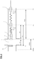
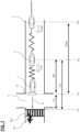
- the intersection passage determination unit 11 has an intersection determination unit 114, a deceleration rate switching position setting unit 111, a stop position acquisition unit 112, and a switching distance acquisition unit 113. Based on information from the map database 103, position information for the host vehicle 1 acquired by the host vehicle position acquisition unit, and a detection result from the detection device 101, the intersection determination unit 114 determines whether or not there is an intersection downstream (ahead) of the host vehicle 1. In addition, the deceleration rate switching position setting unit 111 sets a deceleration rate switching position Pk, which is a predetermined switching determination distance Xa upstream from a traffic light B1, which is a predetermined object in an intersection T, as shown in Fig. 2 .
- the predetermined switching determination distance Xa is a distance at which the detection device 101 of the host vehicle 1 is able to recognize the traffic light B1, which is an object.
- the stop position acquisition unit 112 acquires a stop position Ps, which is a position at which the host vehicle 1 should stop when the state of the object (the traffic light B 1) satisfies a predetermined stop condition.
- the stop position Ps is upstream of the intersection T and downstream of the deceleration rate switching position Pk.
- the stop position Ps is the position of a stop line S displayed on a road surface, but not by way of limitation; the stop position Ps may be the position of an imaginary stop line set by the stop position acquisition unit 112.
- the stop line S does not include a temporary stop line, which is a stop line at which the host vehicle 1 should stop regardless of whether or not the stop condition is satisfied.
- a temporary stop line which is a stop line at which the host vehicle 1 should stop regardless of whether or not the stop condition is satisfied.
- the phrase "when the state of the object satisfies a predetermined stop condition" means, in a case in which the object is the traffic light B1, either, for example, when the traffic light B1 is displaying a stop signal (when the signal color of the traffic light B1 is red), or that the detection device 101 cannot detect the signal color of the traffic light B1.
- the stop signal displayed by the traffic light B1 may also include the signal color of the traffic light B1 being yellow.
- Factors causing the detection device 101 to be unable to detect the signal color of the traffic light B1 are, for example, weather such as a snowstorm, failure of the traffic light B1, road shapes such as a curve, when a preceding vehicle is a large vehicle such as a truck, etc.
- the switching distance acquisition unit 113 acquires a switching distance Xth between the deceleration rate switching position Pk and the stop position Ps.
- the speed limit acquisition unit 12 acquires a speed limit from image information for a speed limit sign detected by the detection device 101, or speed limit information included in navigation data or map data.
- the speed limit is set as an initial vehicle speed Vnow in a deceleration start position P0.
- the vehicle speed profile generation unit 13 generates a vehicle speed profile so that the host vehicle 1 stops as the stop position Ps when the state of the object satisfies a predetermined stop condition.
- the vehicle speed profile generation unit 13 has a primary deceleration profile generation unit 131, a secondary deceleration profile generation unit 132, and an imaginary deceleration profile generation unit 133.
- a primary deceleration profile generated by the primary deceleration profile generation unit 131 and a secondary deceleration profile generated by the secondary deceleration profile generation unit 132 each have an initial vehicle speed Vnow for the host vehicle 1 in the deceleration start position P0, an initial distance Xnow between the deceleration start position P0 and the stop position Ps, a switching vehicle speed Vth of the host vehicle 1 in the deceleration rate switching position Pk, and a switching distance Xth between the deceleration rate switching position Pk and the stop position Ps.
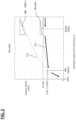
- the primary deceleration profile generation unit 131 generates a primary deceleration profile G1 so that the host vehicle 1 decelerates at a predetermined primary deceleration rate Acoast between the deceleration start position P0 and the deceleration rate switching position Pk, as shown in the graph of Fig. 3 .
- the primary deceleration rate Acoast is a deceleration rate (e.g., 0.04 G) that does not cause the brake lights of the host vehicle 1 to light up.
- the primary deceleration rate Acoast is calculated according to the following formula (1) based on the initial vehicle speed Vnow at the deceleration start position P0 and the initial distance Xnow between the deceleration start position P0 and the stop position Ps, such that the vehicle speed of the host vehicle 1 will reach a predetermined switching vehicle speed Vth at the deceleration rate switching position Pk.
- a coast V now 2 ⁇ V th 2 2 ⁇ X now ⁇ X th
- an imaginary position Poffset at which the vehicle speed of the host vehicle 1 will reach 0 is set as shown in Fig. 2 .
- the vehicle speed V of the host vehicle 1 in the primary deceleration profile is calculated according to the following formula (2) based on the primary deceleration rate Acoast and an imaginary distance Xoffset between the stop position Ps and the imaginary position Poffset.
- the imaginary distance Xoffset is a negative value because the imaginary position Poffset is downstream of the stop position Ps.
- V 2 ⁇ A coast ⁇ X ⁇ X offset
- the secondary deceleration profile generation unit 132 generates a secondary deceleration profile G2 so that the host vehicle 1 decelerates at a predetermined secondary deceleration rate Ath between the deceleration rate switching position Pk and the stop position Ps, as shown in the graph of Fig. 3 .
- the vehicle speed V of the host vehicle 1 is calculated according to the following formula (3) based on the switching vehicle speed Vth, so that the host vehicle 1 will stop at the stop position Ps.
- the secondary deceleration profile generation unit 132 sets the secondary deceleration rate Ath so as to be higher than the primary deceleration rate Acoast.
- the secondary deceleration rate Ath is a deceleration rate (e.g., 0.25 G) that does not impair the riding comfort of occupants of the host vehicle 1.
- V 2 ⁇ A th ⁇ X
- the vehicle speed profile generation unit 13 generates a vehicle speed profile so that the host vehicle 1 travels at the initial vehicle speed Vnow until the deceleration start position P0 and decelerates at the primary deceleration rate Acoast between the deceleration start position P0 and the stop position Ps, as shown by the arrows in Fig. 3 .
- the vehicle speed profile generation unit 13 generates a vehicle speed profile so that the host vehicle 1 decelerates at a secondary deceleration rate Ath higher than the primary deceleration rate Acoast between the deceleration rate switching position Pk and the stop position Ps, and the host vehicle 1 stops at the stop position Ps when the object satisfies a stop condition.
- the vehicle speed profile generation unit 13 generates a vehicle speed profile so that when the state of the object satisfies a stop condition at the moment in time when the host vehicle 1 passes through the deceleration rate switching position Pk, the host vehicle 1, which had been decelerating at the primary deceleration rate Acoast between the deceleration start position P0 and the deceleration rate switching position Pk, will decelerate at the secondary deceleration rate Ath and stop at the stop position Ps after passing through the deceleration rate switching position Pk.
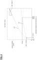
- the secondary deceleration profile generation unit 132 sets the secondary deceleration rate Ath based on the switching distance Xth between the deceleration rate switching position Pk and the stop position Ps. That is, the secondary deceleration rate Ath is set so that a secondary deceleration rate Ath2, which corresponds to a second switching distance Xth2 that is shorter than a first switching distance Xth1 shown in Fig. 4 , will be higher than a secondary deceleration rate Ath1, which corresponds to a first switching distance Xth1 shown in Fig. 3 .
- the secondary deceleration profile generation unit 132 sets the secondary deceleration rate Ath so as to increase commensurately with a decrease in the switching distance Xth.
- the secondary deceleration profile generation unit 132 sets the secondary deceleration rate Ath using a predetermined secondary deceleration rate upper limit value Alim as an upper limit.
- the vehicle speed profile generation unit 13 adjusts the switching vehicle speed Vth in accordance with the secondary deceleration rate upper limit value Alim.
- the primary deceleration profile generation unit 131 generates a primary deceleration profile in accordance with the secondary deceleration rate upper limit value Alim and the switching vehicle speed Vth.
- the secondary deceleration rate upper limit value Alim is an upper limit value of a deceleration rate that does not impair the riding comfort of the occupants of the host vehicle 1 and does not have an undue effect on other following vehicles (the deceleration of the host vehicle 1 is not rapid).
- the vehicle speed profile generation unit 13 sets the switching vehicle speed Vth based on the switching distance Xth between the deceleration rate switching position Pk and the stop position Ps. That is, the switching vehicle speed Vth is set so that a switching vehicle speed Vth2, which corresponds to a second switching distance Xth2 that is shorter than the first switching distance Xth1 shown in Fig. 4 , will be lower than a switching vehicle speed Vth1, which corresponds to the first switching distance Xth1 shown in Fig. 3 . That is, the vehicle speed profile generation unit 13 sets the switching distance Xth so as to decrease commensurately with a decrease in the switching distance Xth.
- the vehicle speed profile generation unit 13 sets the switching vehicle speed Vth using a predetermined vehicle speed upper limit value Vlim as an upper limit.
- the vehicle speed profile generation unit 13 sets the vehicle speed upper limit value Vlim as the switching vehicle speed Vth
- the primary deceleration profile generation unit 131 and the secondary deceleration profile generation unit 132 generate a primary deceleration profile and a secondary deceleration profile in accordance with the vehicle speed upper limit value Vlim.
- the vehicle speed upper limit value Vlim is set to a value that is lower than the speed limit (the initial vehicle speed Vnow).
- the vehicle speed profile generation unit 13 sets the deceleration start position P0 based on the switching determination distance Xa, as shown in Figs. 3 and 4 .
- the switching determination distance Xa is a first switching determination distance Xa1
- the switching determination distance Xa is a second switching determination distance Xa2 shorter than the first switching determination distance Xa1.
- the stop position Ps is the same position.
- the deceleration start position P0 is set such that a deceleration start position P02 corresponding to the second switching determination distance Xa2 shown in Fig.
- the deceleration start position P0 is set so as to be positioned commensurately farther downstream with a decrease in the switching determination distance Xa.
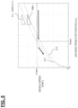
- the imaginary deceleration rate profile generation unit 133 of the vehicle speed profile generation unit 13 shown in Fig. 1 calculates an imaginary deceleration rate Ax for a case assuming that the host vehicle 1 decelerates at a constant imaginary deceleration rate Ax between the deceleration start position P0 and the stop position Ps and stops at the stop position Ps, as shown in Fig. 5 .
- the vehicle speed profile generation unit 13 generates an imaginary deceleration profile G3 based on the imaginary deceleration rate Ax.
- the vehicle speed profile generation unit 13 When the imaginary deceleration rate Ax is higher than the secondary deceleration rate upper limit value Alim, the vehicle speed profile generation unit 13 generates a vehicle speed profile again such that the host vehicle 1 decelerates at the imaginary deceleration rate Ax between the deceleration start position P0 and the stop position Ps, as shown by the arrows in Fig. 5 . That is, when the moment in time that the intersection passage determination unit 11 determines will be the moment the host vehicle 1 will pass through the intersection T is later than a predetermined moment referencing a deceleration rate switching moment at which the host vehicle 1 will pass through the deceleration rate switching position Pk, the imaginary deceleration rate Ax will be higher than the secondary deceleration rate upper limit value Alim. In this case, the vehicle speed profile generation unit 13 selects the imaginary deceleration profile G3 as the vehicle speed profile.
- the secondary deceleration rate assessment unit 14 shown in Fig. 1 assesses whether or not the deceleration rate of the host vehicle 1 will be switched from the primary deceleration rate Acoast to the secondary deceleration rate Ath at the deceleration rate switching position Pk.
- the secondary deceleration rate assessment unit 14 determines whether or not the state of the object satisfies the stop condition at the moment in time when the host vehicle 1 passes through the deceleration rate switching position Pk, and when the state of the object satisfies the stop condition (e.g., when the traffic light B 1 displays a stop signal or when the detection device 101 cannot detect the signal color of the traffic light B 1), the secondary deceleration rate assessment unit 14 assesses that the deceleration rate of the host vehicle 1 will be switched from the primary deceleration rate Acoast to the secondary deceleration rate Ath.
- the vehicle speed profile switching unit 15 switches the vehicle speed profile for after the host vehicle 1 has passed through the deceleration rate switching position Pk from the primary deceleration profile G1 to the secondary deceleration profile G2.
- the vehicle speed profile switching unit 15 when the secondary deceleration rate assessment unit 14 has assessed that the deceleration rate of the host vehicle 1 will not be switched from the primary deceleration rate Acoast to the secondary deceleration rate Ath, the vehicle speed profile switching unit 15, after the host vehicle 1 passes through the deceleration rate switching position Pk, does not switch the vehicle speed profile from the primary deceleration profile G1 to the secondary deceleration profile G2, but cancels executing driving control according to the vehicle speed profile. That is, when the state of the object does not satisfy the stop condition, the vehicle speed V of the host vehicle 1 returns to the initial vehicle speed Vnow and the host vehicle 1 passes through the intersection T at the initial vehicle speed Vnow.
- the host vehicle 1 may pass through the intersection T with the vehicle speed V maintained at the switching vehicle speed Vth.
- the vehicle speed profile switching unit 15 switches the vehicle speed profile so that the host vehicle 1 decelerates at the imaginary deceleration rate Ax or a maximum deceleration rate Amax.
- the vehicle speed profile switching unit 15 cancels executing driving control according to the vehicle speed profile (the imaginary deceleration profile G3) set by the vehicle speed profile generation unit 13. That is, when the imaginary deceleration rate is higher than the predetermined maximum deceleration rate Amax and degree to which the stop condition is satisfied is the predetermined value or lower, the host vehicle 1, without decelerating, passes through the stop position Ps at the initial vehicle speed Vnow.
- the vehicle speed profile switching unit 15 does not cancel execution of driving control according to the vehicle speed profile when the degree to which the stop condition is satisfied is greater than the predetermined value (e.g., when the signal color of the traffic light B1 is red or when a moving object such as a pedestrian is passing through the crosswalk of the intersection T), even if the imaginary deceleration rate Ax is higher than the predetermined maximum deceleration rate Amax. That is, when the imaginary deceleration rate Ax is higher than the predetermined maximum deceleration rate Amax and the degree to which the stop condition is satisfied is greater than the predetermined value, the host vehicle 1 decelerates at the maximum deceleration rate Amax and stops downstream of the stop position Ps.
- the maximum deceleration rate Amax is an upper limit value of the deceleration rate that can be realized by the host vehicle 1.
- the vehicle speed control unit 16 Based on the vehicle speed profile generated by the vehicle speed profile generation unit 13 and the result of the vehicle speed profile being switched by the vehicle speed profile switching unit 15, the vehicle speed control unit 16 outputs a command for controlling the vehicle speed of the host vehicle 1 to the drive control device 104.
- the vehicle speed control unit 16 determines whether or not the state of the object can be determined, and when the state of the object cannot be determined, the vehicle speed control unit 16 starts to execute driving control according to the vehicle speed profile at the deceleration start position P0.
- the detection device 101 cannot detect the signal color of the traffic light B1 while the host vehicle 1 is traveling upstream of the deceleration start position P0, the host vehicle 1 starts to decelerate at the deceleration start position P0 in accordance with the vehicle speed profile generated by the vehicle speed profile generation unit 13.
- step S1 of Fig. 6 the intersection determination unit 114 of the intersection passage determination unit 11 determines whether or not an intersection T exists downstream (ahead) of the host vehicle 1.
- the processor 10 ends the process.
- step S2 When the processor 10 has determined that there is an intersection T downstream of the host vehicle 1, in step S2, the deceleration rate switching position setting unit 111 sets a deceleration rate switching position Pk. Next, in step S3, the stop position acquisition unit 112 acquires a stop position Ps.
- step S4 the primary deceleration profile generation unit 131 and the secondary deceleration profile generation unit 132 generate a primary deceleration profile G1 and a secondary deceleration profile G2, respectively based on the switching determination distance Xa, the initial distance Xnow, and the initial vehicle speed Vnow.
- step S5 the vehicle speed profile generation unit 13 determines whether or not the secondary deceleration rate Ath generated by the secondary deceleration profile generation unit 132 is equal to or less than the secondary deceleration rate upper limit value Alim.
- the vehicle speed profile generation unit 13 sets the secondary deceleration rate Ath again to the secondary deceleration rate upper limit value Alim in step S6, and once more generates a primary deceleration profile and a secondary deceleration profile in step S4.
- step S5 when it has been determined that the secondary deceleration rate Ath is equal to or less than the secondary deceleration rate upper limit value Alim, the vehicle speed profile generation unit 13 determines in step S7 whether or not the switching vehicle speed Vth at the deceleration rate switching position Pk is equal to or less than the vehicle speed upper limit value Vlim.
- the vehicle speed profile generation unit 13 sets the switching vehicle speed Vth again to the vehicle speed upper limit value Vlim in step S8, and once more generates a primary deceleration profile and a secondary deceleration profile in step S4.
- step S7 when it has been determined in step S7 that the switching vehicle speed Vth is equal to or less than the vehicle speed upper limit value Vlim, the vehicle speed profile generation unit 13 determines in step S9 whether or not the imaginary deceleration rate Ax generated by the imaginary deceleration rate profile generation unit 133 is equal to or less than the secondary deceleration rate upper limit value Alim.
- step S10 the vehicle speed profile generation unit 13 determines whether or not the imaginary deceleration rate Ax is equal to or less than the maximum deceleration rate Amax.
- the vehicle speed profile generation unit 13 generates a vehicle speed profile again such that the host vehicle 1 will decelerate at the imaginary deceleration rate Ax between the deceleration start position P0 and the stop position Ps.
- step S12 the processor 10 determines whether or not the degree to which the state of the object satisfies the stop condition is equal to or less than a predetermined value. Specifically, when the object is a traffic light B 1, in step S12, the processor 10 determines that the degree to which the state of the object satisfies the stop condition is equal to or less than the predetermined value when the signal color of the traffic light B 1 is yellow or green.
- step S13 the vehicle speed profile generation unit 13 generates a vehicle speed profile again such that the host vehicle 1 will decelerate at the maximum deceleration rate Amax between the deceleration start position P0 and the stop position Ps.
- step S14 the vehicle speed profile switching unit 15 cancels operation control according to the vehicle speed profile so that the host vehicle 1 will not decelerate and will pass through the stop position Ps at the initial vehicle speed Vnow.
- step S15 the vehicle speed profile generation unit 13 determines whether or not the state of the object satisfies the stop condition.
- the phrase "when the state of the object satisfies the stop condition” means, for example, when the traffic light B1 is displaying a stop signal or when the detection device 101 of the host vehicle 1 is unable to detect the signal displayed by the traffic light B 1.
- the phrase "when the state of the object does not satisfy the stop condition” means, for example, when the detection device 101 of the host vehicle 1 has detected that the signal color of the traffic light B 1 is green.
- step S15 When it has been determined in step S15 that the state of the object satisfies the stop condition, the vehicle speed profile switching unit 15 switches the deceleration rate of the host vehicle 1 from the primary deceleration rate Acoast to the secondary deceleration rate Ath at the deceleration rate switching position Pk.
- step S17 the vehicle speed profile switching unit 15 cancels executing driving control according to the vehicle speed profile, so that the host vehicle 1 will pass through the intersection T at the initial vehicle speed Vnow.
- the driving control device 100 may omit the process of steps S5 and S6, the process of steps S7 and S6, and the process of steps S9 to S14.
- the driving control device 100 may omit all the processes of steps S5 to S14, and after the vehicle speed profile generation unit 13 has generated a primary deceleration profile G1 in step S4, the driving control device 100 may determine in step S15 whether or not the state of the object satisfies the stop condition.
- the processor 10 of the driving control device 100 sets a deceleration rate switching position Pk, which is a predetermined switching determination distance Xa upstream from a predetermined object (traffic light B 1) in an intersection T.
- the processor 10 acquires a stop position Ps that is upstream of the intersection T and downstream of the deceleration rate switching position.
- the vehicle speed profile generation unit 13 of the processor 10 then generates a vehicle speed profile such that the host vehicle 1 will decelerate at a primary deceleration rate Acoast between a predetermined deceleration start position P0 and the deceleration rate switching position Pk, decelerate at a secondary deceleration rate Ath higher than the primary deceleration rate Acoast between the deceleration rate switching position Pk and the stop position Ps, and stop at the stop position Ps when the state of the object satisfied a predetermined stop condition.
- the driving control device 100 thereby sets, in advance, a deceleration rate switching position Pk that is a predetermined switching determination distance Xa from a predetermined object, and an unnecessary secondary deceleration rate is therefore not generated when the host vehicle 1 stops at the stop position Ps. Therefore, the driving control device 100 can switch the deceleration rate from the primary deceleration rate Acoast to the secondary deceleration rate Ath while reducing the possibility of disturbing the flow of following traffic.
- the driving control device 100 can reduce any discomfort felt by occupants as the host vehicle 1 decelerates, and can improve the ride comfort for the occupants of the host vehicle 1.
- the processor 10 of the driving control device 100 determines whether or not the state of the object can be determined, and when the state of the object cannot be determined, the processor 10 starts to execute driving control according to the vehicle speed profile at the deceleration start position P0. That is, even if the detection device 101 cannot detect the state of the object, the host vehicle 1 will start decelerating at the primary deceleration rate Acoast after passing through the deceleration start position P0.
- the driving control device 100 can thereby control the driving of the host vehicle 1 in advance so that the host vehicle 1 will be able to stop at the stop position Ps when it has been determined that the state of the object satisfies the stop condition.
- the processor 10 of the driving control device 100 determines whether or not the state of the object satisfies a stop condition, and when the state of the object does not satisfy the stop condition, the processor 10 cancels executing driving control according to the vehicle speed profile.
- the driving control device 100 can thereby control the driving of the host vehicle 1 so that the host vehicle 1 passes through the intersection T without stopping at the stop position Ps when it has been determined that the state of the object does not satisfy a stop condition.
- the processor 10 of the driving control device 100 determines whether or not the state of the object satisfies a stop condition at the moment in time when the host vehicle 1 passes through the deceleration rate switching position Pk, and when the state of the object satisfies the stop condition, the processor 10 switches the deceleration rate of the host vehicle 1 from the primary deceleration rate Acoast to the secondary deceleration rate Ath.
- the driving control device 100 can thereby control the vehicle speed of the host vehicle 1 by assessing whether or not to switch the deceleration rate of the host vehicle 1 from the primary deceleration rate Acoast to the secondary deceleration rate Ath at the moment in time when the host vehicle 1 passes through the deceleration rate switching position Pk.
- the processor 10 of the driving control device 100 sets the secondary deceleration rate Ath based on the switching distance Xth between the deceleration rate switching position Pk and the stop position Ps. As shown in Figs. 3 and 4 , the secondary deceleration rate Ath is set such that the secondary deceleration rate Ath corresponding to the second switching distance Xth2, which is shorter than the first switching distance Xth1, is higher than the secondary deceleration rate Ath corresponding to the first switching distance Xth1. That is, the secondary deceleration rate Ath is set so as to increase commensurately with a decrease in the switching distance Xth.
- the driving control device 100 can appropriately set the secondary deceleration rate Ath in accordance with the stop position Ps without changing the deceleration rate switching position Pk. That is, the secondary deceleration rate Ath is set higher because the switching distance Xth decreases commensurately with an increase in the distance Xc between the object (traffic light B 1) and the stop position Ps, as shown in Fig. 2 .
- the processor 10 of the driving control device 100 sets the secondary deceleration rate Ath using a predetermined secondary deceleration rate upper limit value Alim as an upper limit.
- the driving control device 100 can thereby minimize rapid deceleration of the host vehicle 1, reduce any discomfort felt by the occupants of the host vehicle 1 during deceleration, and reduce the effect of the deceleration of the host vehicle 1 on the flow of following traffic.
- the processor 10 of the driving control device 100 sets the switching vehicle speed Vth, which is the vehicle speed of the host vehicle 1 at the deceleration rate switching position Pk, based on the switching distance Xth between the deceleration rate switching position Pk and the stop position Ps.
- the switching vehicle speed Vth is set such that the switching vehicle speed Vth corresponding to the second switching distance Xth2, which is shorter than the first switching distance Xth1, is lower than the switching vehicle speed Vth corresponding to the first switching distance Xth1. That is, the switching vehicle speed Vth is set so as to decrease commensurately with a decrease in the switching distance Xth.
- the driving control device 100 can thereby appropriately set the switching vehicle speed Vth in accordance with the stop position Ps without changing the deceleration rate switching position Pk. That is, the switching vehicle speed Vth is set lower because the switching distance Xth decreases commensurately with an increase in the distance Xc between the object (traffic light B1) and the stop position Ps, as shown in Fig. 2 .
- the processor 10 of the driving control device 100 sets the switching vehicle speed Vth using a predetermined vehicle speed upper limit value Vlim as an upper limit.
- the driving control device 100 can thereby prevent the switching vehicle speed Vth from becoming too high when the switching distance Xth is long.
- the driving control device 100 can also prevent the switching vehicle speed Vth from becoming equal to or higher than the speed limit (initial vehicle speed Vnow) by setting the vehicle speed upper limit value Vlim lower than the speed limit (initial vehicle speed Vnow).
- the host vehicle 1 can decelerate at the primary deceleration rate Acoast between the deceleration start position P0 and the deceleration rate switching position Pk.
- the processor 10 of the driving control device 100 calculates an imaginary deceleration rate Ax for when it is assumed that the host vehicle 1 will decelerate at a constant imaginary deceleration rate Ax between the deceleration start position P0 and the stop position Ps and will stop at the stop position Ps.
- the processor 10 When the imaginary deceleration rate Ax is higher than the secondary deceleration rate upper limit value Alim, the processor 10 generates a vehicle speed profile again such that the host vehicle 1 will decelerate at the imaginary deceleration rate Ax between the deceleration start position P0 and the stop position Ps.
- the driving control device 100 can cause the host vehicle 1 to reliably stop at the stop position Ps by causing the host vehicle 1 to rapidly decelerate at the imaginary deceleration rate Ax.
- the processor 10 of the driving control device 100 cancels executing driving control according to the vehicle speed profile. That is, when the imaginary deceleration rate Ax is higher than the maximum deceleration rate Amax and the degree to which the stop condition is satisfied is equal to or less than a predetermined value, the host vehicle 1 will pass through the stop position Ps at the initial vehicle speed Vnow used for the deceleration start position P0.
- the driving control device 100 can cause the host vehicle 1 to smoothly pass through the stop position Ps and the intersection T without decelerating, on the condition that the degree to which the stop condition is satisfied is equal to or less than a predetermined value.
- the switching determination distance Xa is a distance at which the detection device 101 of the host vehicle 1 can recognize the object (traffic light B1).
- the driving control device 100 can thereby set the switching determination distance Xa in accordance with the performance of the detection device 101. Specifically, the driving control device 100 can set the switching determination distance Xa so as to increase commensurately with an increase in the performance of the detection device 101. That is, the driving control device 100 can generate a vehicle speed profile corresponding to the performance of the detection device 101.
- the "distance at which the detection device 101 of the host vehicle 1 can recognize the object” may be the upper limit value of the distance at which the detection device 101 can recognize the object, or a distance shorter than the upper limit value of the distance at which the detection device 101 can recognize the object.
- the "distance at which the detection device 101 of the host vehicle 1 can recognize the object” may also change based on not only the performance of the detection device 101, but also the travel environment such as the weather.
- the processor 10 of the driving control device 100 sets a deceleration start position P0 based on the switching determination distance Xa. As shown in Figs. 3 and 4 , the deceleration start position P0 is set such that the deceleration start position P02 corresponding to the second switching determination distance Xa2, which is shorter than the first switching determination distance Xa1, is positioned farther downstream than the deceleration start position P01 corresponding to the first switching determination distance Xa1.
- the driving control device 100 can thereby set an area (between the deceleration start position P0 and the deceleration rate switching position Pk) in which the host vehicle 1 will decelerate at the primary deceleration rate Acoast in accordance with the switching determination distance Xa.
- the object, of which the state is detected by the detection device 101 is a traffic light B 1 installed in the intersection T.
- the stop condition is that the traffic light B1 is displaying a stop signal or that the detection device 101 of the host vehicle 1 cannot detect the signal displayed by the traffic light.
- the driving control device 100 can thereby cause the host vehicle 1 to decelerate in stages at the primary deceleration rate Acoast and the secondary deceleration rate Ath and stop at the stop position Ps while the traffic light B 1 of the intersection T is displaying a stop signal (while the signal color is red) or while the detection device 101 cannot detect the signal displayed by the traffic light due to inclement weather, a malfunction of the traffic light B 1, road shapes such as a curve, obstruction by a large vehicle, etc.
- the object, of which the state is detected by the detection device 101 is not limited to a traffic light B1; the object may be a crosswalk B2 that intersects the travel route R of the host vehicle 1, as shown in Fig. 7 .
- the stop condition is that a moving object M such as a pedestrian exists in the crosswalk B2, or that the detection device 101 of the host vehicle 1 cannot detect the presence or the absence of a moving object M in the crosswalk B2.
- a pedestrian is not given as a limitation as to the moving object M; the moving object M may be a bicycle, a wheelchair, or the like.
- the driving control device 100 can cause the host vehicle 1 to decelerate in two stages at the primary deceleration rate Acoast and the secondary deceleration rate Ath and stop at the stop position Ps upstream of the intersection T.
- Reasons why the detection device 101 cannot detect the presence or absence of a moving object M in the crosswalk B2 include, for example, inclement weather, road shapes such as a curve, obstruction by a large vehicle, etc.
- the driving control device 100 causes the host vehicle 1 to decelerate in two stages at the primary deceleration rate Acoast and the secondary deceleration rate Ath when the state of the object satisfies a stop condition, but these examples are not provided by way of limitation; the driving control device 100 may case the host vehicle 1 to decelerate in three stages as shown in Figs. 8 and 9 .
- the primary deceleration rate Acoast includes a low primary deceleration rate Acoast1 and a high primary deceleration rate Acoast2 that is higher than the low primary deceleration rate Acoast1.
- the vehicle speed profile generation unit 13 sets an intermediate deceleration rate switching position Pkm between the deceleration start position P0 and the deceleration rate switching position Pk, as shown in Fig. 8 .
- the distance between the stop position Ps and the intermediate deceleration rate switching position Pkm is an intermediate switching distance Xm.
- the primary deceleration profile generation unit 131 of the vehicle speed profile generation unit 13 generates a low primary deceleration profile G11 for the host vehicle 1 to decelerate at the low primary deceleration rate Acoast1 and a high primary deceleration profile G12 for the host vehicle 1 to decelerate at the high primary deceleration rate Acoast2, as shown in Fig. 9 .
- the vehicle speed profile generation unit 13 When the state of the object satisfies a stop condition, the vehicle speed profile generation unit 13 generates a vehicle speed profile such that the primary deceleration rate Acoast will switch from the low primary deceleration rate Acoast1 to the high primary deceleration rate Acoast2 at the moment in time when the host vehicle 1 passes through the intermediate deceleration rate switching position Pkm.
- the driving control device 100 may set a plurality of intermediate deceleration rate switching positions Pkm between the deceleration start position P0 and the deceleration rate switching position Pk and cause the host vehicle 1 to decelerate in four or more stages.
- the primary deceleration rate Acoast is constituted of three or more deceleration rates
- the vehicle speed profile generation unit 13 generates a vehicle speed profile such that the primary deceleration rate Acoast will switch from a predetermined deceleration rate to a deceleration rate that is higher than the predetermined deceleration rate at the moments in time when the host vehicle 1 passes through each of the intermediate deceleration rate switching positions Pkm.
- the driving control device 100 may set one or more intermediate deceleration rate switching positions Pkm between the deceleration start position P0 and the deceleration rate switching position Pk, and may generate a vehicle speed profile such that the primary deceleration rate Acoast will switch from a predetermined deceleration rate to a deceleration rate that is higher than the predetermined deceleration rate at the moments in time when the host vehicle 1 passes through each of the intermediate deceleration rate switching positions Pkm.
- the driving control device 100 can thereby switch the primary deceleration rate Acoast of the host vehicle 1 one or more times between the deceleration start position P0 and the deceleration rate switching position Pk.
- the driving control device 100 can switch the deceleration rate of the host vehicle 1 in three or more stages before causing the host vehicle 1 to stop at the stop position Ps.
- the driving control device 100 can thereby cause the host vehicle 1 to decelerate more smoothly, reduce any discomfort felt by the occupants of the host vehicle 1 at deceleration, and improve ride comfort for the occupants.
Landscapes
- Engineering & Computer Science (AREA)
- Automation & Control Theory (AREA)
- Transportation (AREA)
- Mechanical Engineering (AREA)
- Physics & Mathematics (AREA)
- General Physics & Mathematics (AREA)
- Traffic Control Systems (AREA)
- Control Of Driving Devices And Active Controlling Of Vehicle (AREA)
- Electric Propulsion And Braking For Vehicles (AREA)
Applications Claiming Priority (1)
| Application Number | Priority Date | Filing Date | Title |
|---|---|---|---|
| PCT/IB2021/000673 WO2023052801A1 (fr) | 2021-09-29 | 2021-09-29 | Procédé de commande de conduite et dispositif de commande de conduite |
Publications (2)
| Publication Number | Publication Date |
|---|---|
| EP4411691A1 true EP4411691A1 (fr) | 2024-08-07 |
| EP4411691A4 EP4411691A4 (fr) | 2024-12-25 |
Family
ID=85781408
Family Applications (1)
| Application Number | Title | Priority Date | Filing Date |
|---|---|---|---|
| EP21958594.0A Withdrawn EP4411691A4 (fr) | 2021-09-29 | 2021-09-29 | Procédé de commande de conduite et dispositif de commande de conduite |
Country Status (5)
| Country | Link |
|---|---|
| US (1) | US20250002015A1 (fr) |
| EP (1) | EP4411691A4 (fr) |
| JP (1) | JP7723106B2 (fr) |
| CN (1) | CN118043869A (fr) |
| WO (1) | WO2023052801A1 (fr) |
Families Citing this family (1)
| Publication number | Priority date | Publication date | Assignee | Title |
|---|---|---|---|---|
| US12485766B2 (en) * | 2024-03-28 | 2025-12-02 | Fca Us Llc | System and method for dynamically adjusting coasting regeneration based on environmental information |
Family Cites Families (11)
| Publication number | Priority date | Publication date | Assignee | Title |
|---|---|---|---|---|
| JP5452004B2 (ja) * | 2008-09-24 | 2014-03-26 | 富士重工業株式会社 | 車両の運転支援装置 |
| JP5614079B2 (ja) * | 2010-04-08 | 2014-10-29 | トヨタ自動車株式会社 | 運転支援装置 |
| JP6553469B2 (ja) * | 2015-09-29 | 2019-07-31 | 日立オートモティブシステムズ株式会社 | 車両制御装置 |
| JP6743406B2 (ja) * | 2016-02-19 | 2020-08-19 | いすゞ自動車株式会社 | 走行制御装置及び走行制御方法 |
| US10300894B2 (en) * | 2017-03-13 | 2019-05-28 | Denso International America, Inc. | Auto-braking system for vehicle and method for auto-braking vehicle |
| JP6552064B2 (ja) * | 2017-03-31 | 2019-07-31 | 株式会社Subaru | 車両の走行制御システム |
| JP2019089516A (ja) * | 2017-11-16 | 2019-06-13 | 本田技研工業株式会社 | 車両制御装置、車両制御方法、およびプログラム |
| JP2019172167A (ja) * | 2018-03-29 | 2019-10-10 | アイシン・エィ・ダブリュ株式会社 | 自動運転システムおよび自動運転プログラム |
| JP7110729B2 (ja) * | 2018-05-25 | 2022-08-02 | トヨタ自動車株式会社 | 自動運転システム及び自動運転システムの制御方法 |
| JP7093738B2 (ja) * | 2019-03-08 | 2022-06-30 | 本田技研工業株式会社 | 車両制御装置 |
| JP7379033B2 (ja) * | 2019-09-12 | 2023-11-14 | 日産自動車株式会社 | 運転支援方法及び運転支援装置 |
-
2021
- 2021-09-29 US US18/688,372 patent/US20250002015A1/en active Pending
- 2021-09-29 WO PCT/IB2021/000673 patent/WO2023052801A1/fr not_active Ceased
- 2021-09-29 EP EP21958594.0A patent/EP4411691A4/fr not_active Withdrawn
- 2021-09-29 JP JP2023550731A patent/JP7723106B2/ja active Active
- 2021-09-29 CN CN202180102864.2A patent/CN118043869A/zh active Pending
Also Published As
| Publication number | Publication date |
|---|---|
| WO2023052801A1 (fr) | 2023-04-06 |
| CN118043869A (zh) | 2024-05-14 |
| WO2023052801A8 (fr) | 2023-11-09 |
| US20250002015A1 (en) | 2025-01-02 |
| JP7723106B2 (ja) | 2025-08-13 |
| EP4411691A4 (fr) | 2024-12-25 |
| JPWO2023052801A1 (fr) | 2023-04-06 |
Similar Documents
| Publication | Publication Date | Title |
|---|---|---|
| EP3888986B1 (fr) | Procédé de commande et système de commande pour changement de voie pendant la conduite automatique d'un véhicule, et véhicule | |
| CN109070887B (zh) | 车辆控制系统、车辆控制方法及存储介质 | |
| CN107735302B (zh) | 车辆控制装置、车辆控制方法及存储车辆控制程序的介质 | |
| EP3816964B1 (fr) | Procédé d'aide à la conduite et dispositif de commande de véhicule | |
| EP3819177B1 (fr) | Procédé d'aide au déplacement et dispositif d'aide au déplacement | |
| RU2693183C2 (ru) | Устройство управления движением транспортного средства | |
| EP3220226B1 (fr) | Véhicule automatisé utilisant des profils optimisés de vitesse | |
| EP3848271A1 (fr) | Procédé et dispositif de commande de déplacement pour véhicule | |
| US11054832B2 (en) | Vehicle control device for setting vehicle offset spacing | |
| JP7185408B2 (ja) | 車両制御装置 | |
| US20190258269A1 (en) | Vehicle control device | |
| EP4137378B1 (fr) | Procédé d'aide au déplacement et dispositif d'aide au déplacement | |
| US10821980B2 (en) | Vehicle control device | |
| US20190258259A1 (en) | Vehicle control device | |
| US20190266889A1 (en) | Vehicle control device | |
| US20190256098A1 (en) | Vehicle control device | |
| EP4169787B1 (fr) | Procédé d'aide au déplacement et dispositif d'aide au déplacement | |
| CN115707333B (zh) | 驾驶控制方法及驾驶控制装置 | |
| EP4112404B1 (fr) | Procédé de commande de véhicule et dispositif de commande de véhicule | |
| JP7208106B2 (ja) | 走行支援方法および走行支援装置 | |
| JP2020045039A (ja) | 車両制御方法及び車両制御装置 | |
| EP4411691A1 (fr) | Procédé de commande de conduite et dispositif de commande de conduite | |
| JP7471150B2 (ja) | 走行支援方法、及び、走行支援装置 | |
| JP7351076B2 (ja) | 電動車両の制御方法、及び、電動車両の制御装置 | |
| US12594968B2 (en) | Vehicle driving switching device, vehicle driving system, and vehicle driving switching method |
Legal Events
| Date | Code | Title | Description |
|---|---|---|---|
| STAA | Information on the status of an ep patent application or granted ep patent |
Free format text: STATUS: THE INTERNATIONAL PUBLICATION HAS BEEN MADE |
|
| PUAI | Public reference made under article 153(3) epc to a published international application that has entered the european phase |
Free format text: ORIGINAL CODE: 0009012 |
|
| STAA | Information on the status of an ep patent application or granted ep patent |
Free format text: STATUS: REQUEST FOR EXAMINATION WAS MADE |
|
| 17P | Request for examination filed |
Effective date: 20240418 |
|
| AK | Designated contracting states |
Kind code of ref document: A1 Designated state(s): AL AT BE BG CH CY CZ DE DK EE ES FI FR GB GR HR HU IE IS IT LI LT LU LV MC MK MT NL NO PL PT RO RS SE SI SK SM TR |
|
| A4 | Supplementary search report drawn up and despatched |
Effective date: 20241126 |
|
| RIC1 | Information provided on ipc code assigned before grant |
Ipc: B60W 30/18 20120101ALI20241121BHEP Ipc: B60W 30/14 20060101ALI20241121BHEP Ipc: G08G 1/16 20060101AFI20241121BHEP |
|
| DAV | Request for validation of the european patent (deleted) | ||
| DAX | Request for extension of the european patent (deleted) | ||
| STAA | Information on the status of an ep patent application or granted ep patent |
Free format text: STATUS: EXAMINATION IS IN PROGRESS |
|
| 17Q | First examination report despatched |
Effective date: 20250801 |
|
| STAA | Information on the status of an ep patent application or granted ep patent |
Free format text: STATUS: THE APPLICATION HAS BEEN WITHDRAWN |
|
| 18W | Application withdrawn |
Effective date: 20250930 |