EP4411768A1 - Unité d'actionnement pour un appareil de commutation - Google Patents
Unité d'actionnement pour un appareil de commutation Download PDFInfo
- Publication number
- EP4411768A1 EP4411768A1 EP23154957.7A EP23154957A EP4411768A1 EP 4411768 A1 EP4411768 A1 EP 4411768A1 EP 23154957 A EP23154957 A EP 23154957A EP 4411768 A1 EP4411768 A1 EP 4411768A1
- Authority
- EP
- European Patent Office
- Prior art keywords
- cam
- lever member
- assembly
- actuation unit
- unit
- Prior art date
- Legal status (The legal status is an assumption and is not a legal conclusion. Google has not performed a legal analysis and makes no representation as to the accuracy of the status listed.)
- Pending
Links
- 230000008878 coupling Effects 0.000 claims abstract description 6
- 238000010168 coupling process Methods 0.000 claims abstract description 6
- 238000005859 coupling reaction Methods 0.000 claims abstract description 6
- 230000033001 locomotion Effects 0.000 claims description 23
- 230000006835 compression Effects 0.000 claims description 6
- 238000007906 compression Methods 0.000 claims description 6
- 230000003993 interaction Effects 0.000 claims description 5
- 230000009467 reduction Effects 0.000 claims description 4
- 229910000639 Spring steel Inorganic materials 0.000 claims description 3
- 239000000463 material Substances 0.000 claims description 3
- 230000005540 biological transmission Effects 0.000 description 12
- 125000006850 spacer group Chemical group 0.000 description 9
- 230000007246 mechanism Effects 0.000 description 4
- 230000002860 competitive effect Effects 0.000 description 2
- 230000001419 dependent effect Effects 0.000 description 2
- 230000005489 elastic deformation Effects 0.000 description 2
- 238000012423 maintenance Methods 0.000 description 2
- 230000007704 transition Effects 0.000 description 2
- 239000004020 conductor Substances 0.000 description 1
- 230000006866 deterioration Effects 0.000 description 1
- 230000000694 effects Effects 0.000 description 1
- 238000000034 method Methods 0.000 description 1
- 230000000116 mitigating effect Effects 0.000 description 1
- 238000000465 moulding Methods 0.000 description 1
- 230000008569 process Effects 0.000 description 1
- 238000005096 rolling process Methods 0.000 description 1
- 238000000638 solvent extraction Methods 0.000 description 1
- 230000001960 triggered effect Effects 0.000 description 1
Images


Classifications
-
- H—ELECTRICITY
- H01—ELECTRIC ELEMENTS
- H01H—ELECTRIC SWITCHES; RELAYS; SELECTORS; EMERGENCY PROTECTIVE DEVICES
- H01H3/00—Mechanisms for operating contacts
- H01H3/22—Power arrangements internal to the switch for operating the driving mechanism
- H01H3/30—Power arrangements internal to the switch for operating the driving mechanism using spring motor
- H01H3/3005—Charging means
- H01H3/3015—Charging means using cam devices
-
- H—ELECTRICITY
- H01—ELECTRIC ELEMENTS
- H01H—ELECTRIC SWITCHES; RELAYS; SELECTORS; EMERGENCY PROTECTIVE DEVICES
- H01H33/00—High-tension or heavy-current switches with arc-extinguishing or arc-preventing means
- H01H33/02—Details
- H01H33/28—Power arrangements internal to the switch for operating the driving mechanism
- H01H33/40—Power arrangements internal to the switch for operating the driving mechanism using spring motor
Definitions
- the present invention relates to the field of electrical systems operating at low or medium voltage levels.
- the present invention relates to an actuation unit for a switching apparatus operating at low or medium voltage levels.
- Switching apparatuses such as circuit breakers, contactors, disconnectors and the like, are widely used in switchgears, electric power distribution lines, or other electrical systems.
- a switching apparatus typically comprises a plurality of electric poles, each including a fixed contact and a movable contact.
- the movable contacts of the electric poles are mechanically and electrically coupled with and decoupled from the corresponding fixed contacts during closing and opening manoeuvres of the switching apparatus.
- a switching apparatus generally comprises an actuation unit operatively coupled to the movable contacts in order to move reversibly these latter between the above-mentioned coupled and uncoupled positions relative to said fixed contacts.
- such an actuation unit comprises a rotating contact shaft mechanically coupled to the movable contacts of the electric poles and mechanical actuation means mechanically coupled to said contact shaft for actuating this latter (and consequently the movable contacts of the electric poles) during a closing manoeuvre of the switching apparatus.
- said mechanical actuation means are of the spring-operated type. They comprise one or more actuation springs mechanically coupled to the contact shaft through a suitable kinematic chain. During a closing manoeuvre of the switching apparatus, the actuation springs are triggered to pass from a loaded condition to a released condition. In this way, the stored mechanical energy can be transmitted through the above-mentioned kinematic chain and be employed to actuate the contact shaft.
- the actuation unit comprises mechanical loading means coupled to the kinematic chain linking the actuation springs to the contact shaft.
- these mechanical loading means include an actuator operable by a user, for example a lever mechanism or an electric motor, and a rotating cam assembly mechanically coupled to said actuator and to a lever member of said kinematic chain.
- the cam assembly includes suitable cam elements to actuate the above-mentioned lever member.
- a user activates the above-mentioned actuator.
- This latter actuates the cam assembly, which in turn actuates the lever member coupled thereto and, consequently, bring the actuation springs in a loaded condition.
- the actuation springs can store the mechanical energy necessary to carry out a closing manoeuvre of the switching apparatus.
- the above-mentioned cam assembly moves back to a rest position upon actuation by the above-mentioned lever member as the actuation springs release the stored mechanical energy.
- the actuation unit of currently available switching apparatuses has some aspects to improve in relation to the above-mentioned mechanical loading means.
- the cam assembly comes back to the rest position with a high rotational speed as it is subject to high actuation forces imparted by the above-mentioned lever member.
- the cam assembly When reaching the above-mentioned rest position, the cam assembly typically hits with strength some surrounding components, for example parts of the above-mentioned lever member, which operates, in practice, as an end-of-run element for the cam assembly.
- the main aim of the present invention is to provide an actuation unit for a switching apparatus operating at low or medium voltage levels, which allows solving or mitigating the above-mentioned problems.
- the present invention is aimed at providing an actuation unit, which has a relatively simple and space-saving structure.
- Still another object of the present invention is to provide an actuation unit, which can be easily manufactured at industrial level, at competitive costs with respect to the solutions of the state of the art.
- the present invention provides an actuation unit for a switching apparatus, according to the following claim 1 and the related dependent claims.
- the actuation unit is configured to actuate one or more movable contacts of the switching apparatus during a closing manoeuvre and an opening manoeuvre of said switching apparatus.
- the actuation unit comprises a contact shaft, which is coupled to the movable contacts of the switching apparatus and is reversibly movable about a corresponding first rotation axis, and first mechanical actuation means, which are coupled to said contact shaft and are configured to actuate said contact shaft during a closing manoeuvre of said switching apparatus.
- the first mechanical actuation means comprise a spring assembly including one or more spring elements.
- the spring assembly is configured to take reversibly a loaded condition, at which said spring elements are loaded and consequently store mechanical energy, and a released condition, at which said spring elements have released the stored mechanical energy.
- the first mechanical actuation means further comprise a kinematic chain coupling the spring assembly to the contact shaft.
- a kinematic chain includes a first lever member movable about a second rotation axis parallel to the first rotation axis of the contact shaft and coupled to the spring assembly.
- the first lever member is configured to move reversibly, by rotating according to opposite directions about said second rotation axis, between a first position, which corresponds to a loaded condition of said spring assembly, and a second position, which corresponds to a released condition of said spring assembly.
- the actuation unit further comprises mechanical loading means configured to actuate said first lever member in order to make said spring assembly pass from said released condition to said loaded condition.
- Said mechanical loading means comprise a cam assembly movable about a third rotation axis parallel to the first rotation axis of the contact shaft and including one or more cam units, each having a cam surface couplable to said first lever member.
- Said cam assembly is configured to move reversibly, by rotating about said third rotation axis according to a predefined direction, between a third position, which corresponds to a first position of said first lever member, and a fourth position, which corresponds to a second position of said first lever member.
- said cam assembly actuates said first lever member and makes said first lever member move from said second position to said first position, when said cam assembly moves from said fourth position to said third position upon actuation by an actuating device coupled to said cam assembly.
- Said cam assembly holds said first lever member when said cam assembly is in said third position and it leaves said first lever member free to move from said first position to said second position, when said cam assembly moves away from said third position.
- said first lever member actuates said spring assembly and makes said spring assembly pass from said released condition to said loaded condition, when said first lever member moves from said second position to said first position upon actuation by said cam assembly.
- Said first lever member holds said spring assembly in said loaded condition when first said lever member is in said first position and it leaves said spring assembly free to pass from said loaded condition to said released condition, when said first lever member moves away from said first position.
- the actuation unit comprises mechanically interacting brake members to brake said cam assembly, when this latter moves from said third position to said fourth position.
- At least a cam unit comprises a first brake member configured to come into frictional contact with a corresponding second brake member in fixed position relative to said cam unit, during a rotation movement of said cam assembly from the third position to the fourth position.
- the mechanical interaction between said first and second brake members causes a reduction of the rotational speed of said cam assembly while this latter is moving from said third position to said fourth position.
- said first and second brake members are positioned one relative to another, so that said first brake member comes into frictional contact with said second brake member at an initial stage of the rotation movement of said cam assembly from said third position to said fourth position.
- each first brake member is formed by a contoured head protruding from a first surface of a corresponding cam unit, said first surface facing a second surface of a corresponding support wall of said actuation unit, on which a second brake member is arranged.
- each second brake member is formed by an elastically deformable lamina fixed to a second surface of support wall of said actuation unit, which faces a first surface of a corresponding cam unit of said cam assembly, on which a first brake member is arranged.
- each elastically deformable lamina has first and second end regions fixed to said second surface and a bent central region oriented in such a way to protrude from said second surface towards the first surface of a corresponding cam unit, on which a first brake member is arranged.
- each elastically deformable lamina is subject to an elastic compression when the contoured head of a corresponding cam unit comes into frictional contact with said elastically deformable lamina.
- each elastically deformable lamina is made of a spring steel material.
- the above-mentioned spring assembly includes a first end portion fixed to a third support wall, a second end portion opposite to said first end portion and coupled to said first lever member and one or more compression springs arranged between said first and second end portions.
- the above-mentioned first lever member has a third end portion coupled to said spring assembly and a fourth end portion opposite to said first end portion relative to said second rotation axis and coupled to said contact shaft through one or more second lever members.
- Said first lever member further comprises one or more sliding elements arranged at said fourth end portion. Each sliding element has a sliding surface couplable to the cam surface of a corresponding cam unit.
- said cam assembly comprises a pair of cam units spaced apart one from another along third rotation axis.
- Each cam unit has a cam surface couplable to said first lever member and a first surface facing a second surface of a corresponding support wall of said actuation unit.
- the present invention relates to a switching apparatus, according to the following claim 14 and the related dependent claims.
- the present invention relates to an actuation unit for a switching apparatus, such as a circuit breaker, a contactor, a disconnector or the like.
- the actuation unit is particularly suitable for use in medium voltage switching apparatuses, i.e., operating at voltage levels higher than 2.0 kV AC and 2.5 kV DC up to several tens of kV, for example 72 kV AC and 100 kV DC. In principle, however, it may be used also in low-voltage switching apparatuses, i.e., operating at voltage levels lower than 2.0 kV AC and 2.5 kV DC.
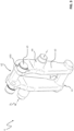
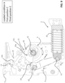
- Figure 1 shows a schematic view of a switching apparatus 100 including an actuation unit 1 according to the invention.
- the switching apparatus 100 comprises one or more electric poles 101.
- the switching apparatus 100 is of the multi-phase type, more particularly of the three-phase type, as shown in the cited figures.
- the switching apparatus 100 For each electric pole 101, the switching apparatus 100 comprises a fixed contact 102 and a movable contact 103, which are electrically connected to corresponding first and second pole terminals 104, 105 electrically connectable to suitable conductors of an electric line.
- each electric pole 101 is reversibly movable between a decoupled position and a coupled position relative to the corresponding fixed contact 102.
- the movable contact 103 When it is in a decoupled position, the movable contact 103 is electrically and mechanically decoupled from the corresponding fixed contact while, when it is in a coupled position, the movable contact 103 is electrically and mechanically coupled with the corresponding fixed contact.
- each movable contact 103 moves translationally along a main longitudinal axis of a corresponding electric pole. In principle, however, the movable contacts of the switching apparatus may move rotationally to couple with or decouple from the corresponding fixed contacts.
- the transition of the movable contacts 103 from a coupled position with to a decoupled position from the corresponding fixed contacts 102 represents an opening manoeuvre of the switching apparatus whereas the transition of the movable contacts 103 from a decoupled position to a coupled position with the corresponding fixed contacts 102 represents a closing manoeuvre of the switching apparatus.
- the electric poles 101 of the switching apparatus may be realized at industrial level according to solutions of known type. Therefore, in the following, these components will be described in relation to the aspects of interest of the invention only, for the sake of brevity.
- the switching apparatus 100 comprises an actuation unit 1 configured to actuate the movable contacts 103 of the electric poles during a closing manoeuvre and an opening manoeuvre of the switching apparatus.
- the actuation unit 1 comprises an outer enclosure 3 and a number of internal support walls 10 partitioning the internal volume of the actuation unit and providing support to the internal components thereof.
- the actuation unit 1 comprises a contact shaft 4 coupled to the movable contacts 103 of the electric poles through suitable motion transmission mechanisms (not shown), for example of the crank-lever type.
- connect- and “couple-” used in this disclosure generally relate to a mechanical connection or coupling between the involved parts or components.
- the terms “connect” or “couple” should be intended as “mechanically couple-” and “mechanically connect-” unless otherwise specified.
- the contact shaft 4 is reversibly movable about a corresponding first rotation axis A 1 preferably oriented along a longer dimension of the actuation unit.
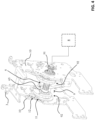
- the actuation unit 1 comprises first mechanical actuation means 5, 6, 7 configured to actuate the contact shaft 4 during a closing manoeuvre of the switching apparatus.
- the above-mentioned first mechanical actuation means comprises a spring assembly 5 including one or more spring elements 50.
- the spring assembly 5 is configured to take reversibly a loaded condition A, at which the spring elements 50 are loaded and store mechanical energy, and a released condition B, at which the spring elements 50 have released the stored mechanical energy.
- the spring assembly 5 includes a first end portion 51 fixed to an internal support 16 of the actuation unit, a second end portion 52 opposite to said first end portion and one or more compression springs 50 arranged between said first and second end portions, conveniently in such a way to be mutually coaxial.
- the above-mentioned first mechanical actuation means further comprises a kinematic chain 6, 7 coupling the spring assembly 5 to the contact shaft 4.
- Such a kinematic chain includes a first lever member 6 configured to rotate about a second rotation axis A 2 parallel to the first rotation axis A 1 of the contact shaft 4.
- the first lever member 6 is coupled to the spring assembly 5 and (indirectly) to the contact shaft 4.
- the first lever member 6 is configured to move reversibly between a first position C, which corresponds to a loaded condition A of the spring assembly 5, and a second position D, which corresponds to a released condition B of the spring assembly 5.
- the first lever member 6 moves between the above-mentioned first and second positions C, D by rotating according to opposite directions Ri, R 2 about the second rotation axis A 2 .
- the first lever member 6 has a third end portion 61 coupled to the spring assembly 5 (namely to the second end portion 52 of this latter) and a fourth end portion 62, which is opposite to the third end portion 61 relative to the rotation axis A 2 and is coupled (indirectly) to the contact shaft 4.
- the first lever member 6 comprises one or more sliding elements 65, each having a sliding surface 650.
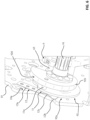
- Figure 3 shows in more details a possible configuration for the first lever member 6 according to the embodiments shown in the cited figures.
- the first lever member 6 comprises first lever arms 63 extending in parallel according to a longer dimension of the first lever member and second lever arms 64 traversal to the first lever arms 63 and joining these latter at the opposite end portions 61, 62 of the first lever member.
- each lever arm 63 has a shaped protrusion 66 oriented outwardly (i.e., according to an opposite direction relative to the other lever arm).
- the shaped protrusions 66 are aligned along the second rotation axis A 2 of the first lever member 6 and are configured to be pivoted on a pair of opposite support walls 10 of the actuation unit ( figures 4-5 ).
- the first lever member 6 further comprises a pair of rollers 65, each protruding outwards from a corresponding lever arm 63 (in parallel to a corresponding protrusion 66).
- the rollers 65 are aligned along an axis parallel to the second axis A 2 .
- the rollers 65 form the above-mentioned sliding elements of the first lever arm 6 and their rolling surfaces 650 form the above-mentioned sliding surfaces.
- the first lever member 6 is coupled (indirectly) with the contact shaft 4.
- the above-mentioned kinematic chain further includes a plurality 7 of second lever members mutually hinged at a plurality of rotation axes parallel to the first rotation axis A 1 of the contact shaft 4 and coupling the first lever member 6 (namely the fourth end portion 62 thereof) to the contact shaft 4.
- the actuation unit 1 comprises also second mechanical actuation means 2 configured to actuate the contact shaft 4 during an opening manoeuvre of said switching apparatus.
- first mechanical actuation means 5, 6, 7 and second mechanical actuation means 2 may be realized at industrial level according to solutions of known type. Therefore, in the following, they will be described only in relation to the aspects of interest of the invention, for the sake of brevity.
- the actuation unit 1 further comprises mechanical loading means 8, 9 configured to actuate the first lever member 6 of the first mechanical actuation means in order to load the spring assembly 5, i.e., bring this latter from the released condition B to the loaded condition A.
- the above-mentioned mechanical loading means advantageously comprise one or more actuating devices 8 that can be activated by a user to load the spring assembly 5.
- the actuating device 8 are configured to provide the mechanical energy necessary to bring the spring assembly 5 from a released condition B to a loaded condition A.
- the actuating devices 8 may include, for example, a lever mechanism that can be manually operated by a user.
- the actuating devices 8 may include an electric motor activatable through a suitable user interface.
- actuating devices 8 may be realized at industrial level according to solutions of known type. Therefore, in the following, they will be described only in relation to the aspects of interest of the invention, for the sake of brevity.
- the above-mentioned mechanical loading means further comprise a cam assembly 9 configured to rotate about a third rotation axis A 3 parallel to the first rotation axis A 1 of the contact shaft.
- the cam assembly 9 includes a motion transmission shaft 91 and one or more cam units 92 coupled to said motion transmission shaft.
- the motion transmission shaft 91 has opposite ends pivoted on opposite support walls 10 of the actuation unit to rotate about the third rotation axis A 3 .
- the motion transmission shaft 91 is coupled to the one or more actuating devices 8, preferably at one of its opposite ends.
- suitable gear mechanisms (not shown) of known type can be employed.
- Each cam unit 92 is coupled to the motion transmission shaft 91 in such a way to rotate together with said motion transmission shaft.
- Each cam unit 92 includes a cam surface 920 couplable to the first lever member 6, more particularly to the sliding surface 650 of a corresponding sliding element 65 of the first lever member.
- Each cam unit 92 further includes a first surface 92a facing a second surface 10a of a corresponding support wall 10.
- the first surface 92a is a side surface facing a support wall 10 of the actuation unit on which the cam assembly 9 is pivoted.
- the second surface 10a is the facing surface of a support wall 10 on which the cam assembly 9 is pivoted.
- the cam assembly 9 comprises a pair of cam units 92 spaced apart one from another along the third rotation axis A 3 and arranged on the motion transmission shaft 91, preferably in proximity of the opposite support walls 10 of the actuation unit 1, on which said motion transmission shaft is pivoted.
- Each cam unit 92 has thus a side surface 92a (first surface) facing an opposite surface 10a (second surface) of a corresponding support wall 10.
- the cam assembly 9 may comprise a single cam unit 92 in proximity of a corresponding support wall 10 of the actuation unit 1.
- Figures 6-8 schematically show a cam unit 92 of the cam assembly 9, according to an embodiment of the invention.
- Each cam unit 92 preferably includes a cam element 921 arranged coaxially with the motion transmission shaft 91 and forming a single piece with this latter.
- the cam element 921 includes an edge surface forming the above-mentioned cam surface 920.
- Each cam unit 92 preferably includes a spacer element 922 fixed to the cam element 921 and interposed between the cam element 921 and a corresponding support wall 10.
- the spacer element 922 includes the above-mentioned first surface 92a.
- the spacer element 922 has a cup-shaped portion, through which the motion transmission shaft 91 can pass. Said cup-shaped portion is fixed to the corresponding cam element 921 in such way to anchor the spacer element 922 to the motion transmission shaft 91.
- the spacer element 922 in distal position from the corresponding cam element 921, has a flat a ring-shaped edge with the first surface 92a facing an opposite second surface 10a of the corresponding support wall 10.
- each cam unit may be configured differently from the solution shown in the cited figures.
- each cam unit may include only the cam element.
- a side surface of the cam element forms the first surface facing a second surface of a corresponding support wall.
- the cam assembly 9 is configured to move reversibly, by rotating about the third rotation axis A 3 according to a same predefined direction R 3 , between a third position E, which corresponds to a first position C of the first lever member 6, and a fourth position F, which corresponds to a second position D of the first lever member 6.
- each cam unit 92 is oriented in such a way that it couples with the sliding surface 650 of a corresponding sliding element 65 of the first lever member 6, when the cam assembly 9 moves from the fourth position F to the third position E.
- the actuation unit 1 comprises mechanical triggering means 13 couplable to the cam assembly 9, more particularly to a cam unit 92 of said cam assembly.
- the triggering means 13 include a trigger lever 130 configured to engage and hold the cam assembly 9 in the third position E once this latter has reached the third position E and to leave the cam assembly 9 free to move from the third position E to the fourth position F, when a closing manoeuvre of said switching apparatus is carried out.
- triggering means 13 may be realized at industrial level according to solutions of known type. Therefore, in the following, they will be described only in relation to the aspects of interest of the invention, for the sake of brevity.
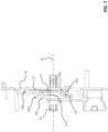
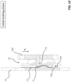
- the spring assembly 5 is supposed to be in a released condition B ( figure 11 ).
- the cam assembly 9 Upon actuation by the actuating device 8, the cam assembly 9 rotates according to the predefined third direction R 3 and moves from the fourth position F ( figure 11 ) towards the third position E ( figure 9 ). During this movement of the cam assembly, the cam surface 920 of each cam unit 92 couples with the sliding surface 650 of a corresponding sliding element 65 of the first lever member 6. The cam assembly 9 thus actuates the first lever member 6, which is moved, according to a first direction Ri, from the second position D ( figure 11 ) towards the first position C ( figure 9 ). In doing so, the first lever member 6 actuates the spring assembly 5 in such a way to compress the spring elements 50 (reference T 1 ). The spring assembly 5 is thus brought from the released condition B ( figure 11 ) to a loaded condition A ( figure 9 ).
- a cam unit 92 of the cam assembly 9 is engaged by the triggering means 13.
- the triggering lever 130 engages a corresponding can unit 92 and holds the whole cam assembly 9 in the third position E.
- the cam assembly 9 holds the first lever member 6 in the first position C and the first lever member 6 holds the spring assembly 5 in the loaded condition A.
- the actuation unit 1 is now ready to drive a closing manoeuvre of the switching apparatus.
- the user activates the triggering means 13.
- the trigger lever 130 moves in such a way to disengage from the cam assembly 9.
- the cam assembly 9 is now free to move from the third position E ( figures 9-10 ) to the fourth position F ( figure 11 ) by rotating always according to the predefined third direction R 3 .
- the cam assembly 9 thus leaves the first lever member 6 free to move from the first position C ( figures 9-10 ) to the second position D ( figure 11 ) by rotating according to a second direction R 2 opposite to the first direction R 1 .
- the first lever member 6 leaves the spring assembly 5 free to pass (reference T 2 ) from the loaded condition A ( figure 9 ) to a released condition B ( figure 11 ).
- the spring assembly 5 releases the stored mechanical energy, which is thus transmitted through the first lever member 6 and the second lever members 7 to the contact shaft 4.
- the contact shaft 4 can actuate the movable contacts 103 of the switching apparatus.
- the first lever 6 actuates the cam assembly 9 while moving away from the first position C. This latter is thus pushed away from the third position E and can freely rotate towards the fourth position F (rest position).
- the actuation unit 1 comprises mechanically interacting brake members 11, 12 configured to brake the cam assembly 9 during the rotation movement from the third position E to the fourth position F (such a rotation movement occurs during a closing manoeuvre of the switching apparatus as explained above).
- At least a cam unit 92 comprises a first brake member 11 configured to come into frictional contact with a corresponding second brake member 12 in fixed position relative to said cam unit, during a rotation movement of said cam assembly 9 from the third position E to the fourth position F.
- the actuation unit 1 comprises a pair of mechanically interacting first and second brake elements 11, 12 for each cam unit 92 of the cam assembly 9.
- the actuation unit 1 may include mechanically interacting brake members 11,12 only for one of the cam units 92 of the cam assembly 9.
- the first and second brake members 11, 12 are positioned one relative to another, so that the first brake member 11 comes into frictional contact with said second brake member 12 at an initial stage of the rotation movement of said cam assembly 9 from the third position E to the fourth position F.
- This solution is particularly advantageous as it allows reducing the rotational speed of the cam assembly, as soon as this latter starts moving. The cam assembly 9 is thus prevented from reaching excessively high values of rotational speed.
- each second brake member 12 is fixed to a support wall 10 of the actuation unit in proximal position to a corresponding cam member 92, namely at a second surface 10a of a corresponding support wall 10, which faces a first surface 92a of a corresponding cam unit 92 of the cam assembly 9.
- the first surface 92a is the side surface of the cam unit 92, on which a first brake member 11 is arranged, while the second surface 10a is the surface of a support wall 10, on which the cam assembly is pivoted.
- Each second brake member 12 is positioned so that it does not interact with the first brake member 11 of the corresponding cam unit 92, when the cam assembly 9 moves from the fourth position F to the third position E (i.e., during the loading of the spring assembly 5), and it comes into frictional contact with the first brake member 11 of the corresponding cam unit 92 only when the cam assembly 9 moves from the third position E to the fourth position F (i.e., during a closing manoeuvre of the witching apparatus).
- each first brake member is formed by a contoured head 11 protruding from the first surface 92a of a corresponding cam unit 92, which faces a second surface 10a of a corresponding support wall 10 on which the cam assembly 9 is pivoted.
- a second brake member 12 is arranged on the second surface 10a.
- each cam unit 92 includes a pin 11a arranged in parallel to the rotation axis A 3 of the cam assembly 92 and passing through the cam element 921 and the spacer element 922 of the cam unit.
- the pin 1 1a has a contoured head 11 protruding from the side surface 92a of the spacer element 922 towards the surface 10a of a corresponding support wall 10.
- Such a contoured head forms the above-mentioned first brake member 11.
- the contoured head 11 can be realized in one piece with the spacer element 922 (e.g., through a moulding process) or can be the protruding head of a pin fixed to the spacer element 922 only.
- each cam unit comprises only a cam element
- the above-mentioned contoured head is formed on the side surface of said cam element, which faces the surface of a corresponding support wall on which the cam assembly is pivoted.
- each second brake member is formed by an elastically deformable lamina 12 fixed to the second surface 10a of a corresponding support wall 10, which faces a first surface 92a of a corresponding cam unit 92 of the cam assembly 9.
- each elastically deformable lamina is made of a spring steel material.
- each deformable lamina 12 is fixed to the surface 10a of a corresponding support wall 10, which faces the first surface 92a of a corresponding cam unit 92.
- a first brake member 12 is arranged on the first surface 92a.
- each deformable lamina is fixed to the surface of a corresponding support wall, which faces the side surface of the cam element of a corresponding cam unit.
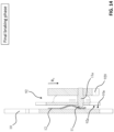
- each deformable lamina 12 has first and second end regions 12a, 12b fixed to the surface 10a of the corresponding support wall 10 and a bent central region 12c oriented in such a way to protrude from the second surface 10a towards a corresponding cam unit 92.
- the bent central region 12c of each deformable lamina 12 is subject to an elastic compression when a first brake member 11 of a corresponding cam unit 92 comes in frictional contact of with the deformable lamina.
- the contoured head 11 reaches the bent portion 12c of the corresponding deformable lamina 12, which is thus subject to an elastic deformation.
- the elastic deformation of the bent portion 12c increases remarkably the dissipation of kinetic energy of the cam assembly 9.
- the cam assembly 9 is subject to a maximum decrease of rotational speed.
- each contoured head 11 and the corresponding deformable lamina 12 occurs at an initial stage of the rotational movement of the cam assembly 9, i.e., before this latter rotates at its maximum speed levels. It has been seen that this solution allows preventing even more effectively possible structural damages of components hit by the cam assembly 9, when this latter reaches its rest position F.
- the actuation unit 1, according to the invention provides remarkable advantages with respect to the known apparatuses of the state of the art.
- the arrangement of the first and second brake members 11, 12 allows prolonging remarkably the operating life of the components of the actuation unit, which are configured to interact with the cam units 92 during the rotational movements of the cam assembly 9.
- the arrangement of the first and second brake members 11, 12 in the actuation unit allows preventing or reducing possible structural damages to the sliding elements 65 of the first lever member 6, which are normally hit by the cam units 92, when the cam assembly 9 returns to its rest position F.
- the actuation unit 1, according to the invention can therefore ensure improved levels of reliability in operation, which allows reducing maintenance interventions and costs.
- the first and second brake members 11, 12 can be easily integrated with the structure of the cam units 92 and the adjacent support walls 10.
- the actuation unit 1 can thus be realized with a very simple and compact structure.
- first and second brake members 11, 12 are quite simple and cheap to realize at industrial level.
- the arrangement of these brake members thus does not entail relevant cost increases for the actuation unit 1, which can thus be industrially manufactured at competitive costs with respect to the solutions of the state of the art.
Landscapes
- Braking Arrangements (AREA)
- Driving Mechanisms And Operating Circuits Of Arc-Extinguishing High-Tension Switches (AREA)
Priority Applications (2)
| Application Number | Priority Date | Filing Date | Title |
|---|---|---|---|
| EP23154957.7A EP4411768A1 (fr) | 2023-02-03 | 2023-02-03 | Unité d'actionnement pour un appareil de commutation |
| CN202410025490.4A CN118448188A (zh) | 2023-02-03 | 2024-01-08 | 用于开关设备的致动单元 |
Applications Claiming Priority (1)
| Application Number | Priority Date | Filing Date | Title |
|---|---|---|---|
| EP23154957.7A EP4411768A1 (fr) | 2023-02-03 | 2023-02-03 | Unité d'actionnement pour un appareil de commutation |
Publications (1)
| Publication Number | Publication Date |
|---|---|
| EP4411768A1 true EP4411768A1 (fr) | 2024-08-07 |
Family
ID=85174111
Family Applications (1)
| Application Number | Title | Priority Date | Filing Date |
|---|---|---|---|
| EP23154957.7A Pending EP4411768A1 (fr) | 2023-02-03 | 2023-02-03 | Unité d'actionnement pour un appareil de commutation |
Country Status (2)
| Country | Link |
|---|---|
| EP (1) | EP4411768A1 (fr) |
| CN (1) | CN118448188A (fr) |
Citations (4)
| Publication number | Priority date | Publication date | Assignee | Title |
|---|---|---|---|---|
| JPS5168371U (fr) * | 1974-11-26 | 1976-05-29 | ||
| US5938008A (en) * | 1998-05-07 | 1999-08-17 | Eaton Corporation | Disengageable charging mechanism for spring powered electrical switching apparatus |
| US20030034242A1 (en) * | 2001-08-20 | 2003-02-20 | Mitsubishi Denki Kabushiki Kaisha | Switchgear operating apparatuses |
| US20110076096A1 (en) * | 2009-09-25 | 2011-03-31 | Saint-Gobain Performance Plastics Rencol Limited | System, method and apparatus for tolerance ring control of slip interface sliding forces |
-
2023
- 2023-02-03 EP EP23154957.7A patent/EP4411768A1/fr active Pending
-
2024
- 2024-01-08 CN CN202410025490.4A patent/CN118448188A/zh active Pending
Patent Citations (4)
| Publication number | Priority date | Publication date | Assignee | Title |
|---|---|---|---|---|
| JPS5168371U (fr) * | 1974-11-26 | 1976-05-29 | ||
| US5938008A (en) * | 1998-05-07 | 1999-08-17 | Eaton Corporation | Disengageable charging mechanism for spring powered electrical switching apparatus |
| US20030034242A1 (en) * | 2001-08-20 | 2003-02-20 | Mitsubishi Denki Kabushiki Kaisha | Switchgear operating apparatuses |
| US20110076096A1 (en) * | 2009-09-25 | 2011-03-31 | Saint-Gobain Performance Plastics Rencol Limited | System, method and apparatus for tolerance ring control of slip interface sliding forces |
Also Published As
| Publication number | Publication date |
|---|---|
| CN118448188A (zh) | 2024-08-06 |
Similar Documents
| Publication | Publication Date | Title |
|---|---|---|
| JP4387034B2 (ja) | 回路遮断器 | |
| KR20140112503A (ko) | 아크 접점의 분리를 가속시키기 위한 스프링을 포함하는, 차단기용 가동형 도전 유닛 | |
| EP0746862B1 (fr) | Coupe-circuit a isolement sequentiel et actionneur | |
| CN106796849A (zh) | 电气开关设备及其对应的变速箱总成 | |
| KR100876411B1 (ko) | 차단기의 액츄에이터 리셋 장치 | |
| KR100631006B1 (ko) | 가스절연 개폐장치 | |
| EP4411768A1 (fr) | Unité d'actionnement pour un appareil de commutation | |
| EP4411767A1 (fr) | Unité d'actionnement pour un appareil de commutation | |
| CN201681752U (zh) | 尤其用于多位开关设备的驱动装置 | |
| CA2751698C (fr) | Declencheur manuel pour disjoncteur | |
| KR20120053410A (ko) | 회로차단기의 접점장치 | |
| EP2075813B1 (fr) | Agencement de ressort pour unité de ressort et unité de ressort comportant un agencement de ressort | |
| RU2368974C2 (ru) | Заземляющий переключатель | |
| JP7836944B2 (ja) | 開閉装置の操作機構 | |
| KR200438667Y1 (ko) | 가스절연 개폐장치 | |
| GB2311654A (en) | Circuit breaker with recloser | |
| CN213816030U (zh) | 一种操作机构和断路器 | |
| EP2920805B1 (fr) | Appareil de commutation électrique utilisant ensemble de contact rotatif | |
| EP3696836B1 (fr) | Commutateur pour un appareillage de commutation moyenne ou haute tension | |
| WO2014198290A1 (fr) | Dispositif de commutation haute tension | |
| EP4506974A1 (fr) | Actionneur pour un appareil de commutation électrique, appareil de commutation électrique et procédé | |
| EP2941778B1 (fr) | Ensemble de support de micro-commutateur d'un dispositif de commutation | |
| CN113539728B (zh) | 接地开关和包括该开关的开关装置 | |
| JP7750924B2 (ja) | 断路器またはアーススイッチ | |
| EP2075812A1 (fr) | Dispositif de protection à ressort et unité de commande du ressort incluant le dispositif de protection à ressort |
Legal Events
| Date | Code | Title | Description |
|---|---|---|---|
| PUAI | Public reference made under article 153(3) epc to a published international application that has entered the european phase |
Free format text: ORIGINAL CODE: 0009012 |
|
| STAA | Information on the status of an ep patent application or granted ep patent |
Free format text: STATUS: THE APPLICATION HAS BEEN PUBLISHED |
|
| AK | Designated contracting states |
Kind code of ref document: A1 Designated state(s): AL AT BE BG CH CY CZ DE DK EE ES FI FR GB GR HR HU IE IS IT LI LT LU LV MC ME MK MT NL NO PL PT RO RS SE SI SK SM TR |
|
| STAA | Information on the status of an ep patent application or granted ep patent |
Free format text: STATUS: REQUEST FOR EXAMINATION WAS MADE |
|
| 17P | Request for examination filed |
Effective date: 20250122 |