EP4411774A1 - Dispositif de commutation et procédé de fonctionnement d'un dispositif de commutation - Google Patents
Dispositif de commutation et procédé de fonctionnement d'un dispositif de commutation Download PDFInfo
- Publication number
- EP4411774A1 EP4411774A1 EP24150044.6A EP24150044A EP4411774A1 EP 4411774 A1 EP4411774 A1 EP 4411774A1 EP 24150044 A EP24150044 A EP 24150044A EP 4411774 A1 EP4411774 A1 EP 4411774A1
- Authority
- EP
- European Patent Office
- Prior art keywords
- contact spring
- contour
- switch
- switching device
- rotary shaft
- Prior art date
- Legal status (The legal status is an assumption and is not a legal conclusion. Google has not performed a legal analysis and makes no representation as to the accuracy of the status listed.)
- Pending
Links
- 238000000034 method Methods 0.000 title claims description 8
- 238000010438 heat treatment Methods 0.000 claims abstract description 52
- 230000005540 biological transmission Effects 0.000 claims description 16
- 239000004033 plastic Substances 0.000 claims description 15
- 229920003023 plastic Polymers 0.000 claims description 15
- 239000002184 metal Substances 0.000 claims description 11
- 229910052751 metal Inorganic materials 0.000 claims description 11
- 238000000926 separation method Methods 0.000 claims description 6
- 230000001960 triggered effect Effects 0.000 claims description 5
- 238000010411 cooking Methods 0.000 claims 1
- 125000004122 cyclic group Chemical group 0.000 abstract description 6
- 238000013461 design Methods 0.000 description 4
- 238000002844 melting Methods 0.000 description 4
- 230000008018 melting Effects 0.000 description 4
- 239000000463 material Substances 0.000 description 3
- 238000005452 bending Methods 0.000 description 2
- 239000004020 conductor Substances 0.000 description 2
- 238000001746 injection moulding Methods 0.000 description 2
- 238000012986 modification Methods 0.000 description 2
- 230000004048 modification Effects 0.000 description 2
- 238000013021 overheating Methods 0.000 description 2
- 239000000243 solution Substances 0.000 description 2
- 229920001342 Bakelite® Polymers 0.000 description 1
- RYGMFSIKBFXOCR-UHFFFAOYSA-N Copper Chemical compound [Cu] RYGMFSIKBFXOCR-UHFFFAOYSA-N 0.000 description 1
- 230000004913 activation Effects 0.000 description 1
- 239000004637 bakelite Substances 0.000 description 1
- 239000000919 ceramic Substances 0.000 description 1
- 229910052802 copper Inorganic materials 0.000 description 1
- 239000010949 copper Substances 0.000 description 1
- 230000000694 effects Effects 0.000 description 1
- 238000005265 energy consumption Methods 0.000 description 1
- 238000013507 mapping Methods 0.000 description 1
- 238000007493 shaping process Methods 0.000 description 1
- 238000009423 ventilation Methods 0.000 description 1
Images


Classifications
-
- H—ELECTRICITY
- H01—ELECTRIC ELEMENTS
- H01H—ELECTRIC SWITCHES; RELAYS; SELECTORS; EMERGENCY PROTECTIVE DEVICES
- H01H37/00—Thermally-actuated switches
- H01H37/02—Details
- H01H37/12—Means for adjustment of "on" or "off" operating temperature
- H01H37/14—Means for adjustment of "on" or "off" operating temperature by anticipatory electric heater
-
- H—ELECTRICITY
- H01—ELECTRIC ELEMENTS
- H01H—ELECTRIC SWITCHES; RELAYS; SELECTORS; EMERGENCY PROTECTIVE DEVICES
- H01H89/00—Combinations of two or more different basic types of electric switches, relays, selectors and emergency protective devices, not covered by any single one of the other main groups of this subclass
- H01H89/04—Combination of a thermally actuated switch with a manually operated switch
-
- H—ELECTRICITY
- H01—ELECTRIC ELEMENTS
- H01H—ELECTRIC SWITCHES; RELAYS; SELECTORS; EMERGENCY PROTECTIVE DEVICES
- H01H37/00—Thermally-actuated switches
- H01H37/02—Details
- H01H37/04—Bases; Housings; Mountings
-
- H—ELECTRICITY
- H01—ELECTRIC ELEMENTS
- H01H—ELECTRIC SWITCHES; RELAYS; SELECTORS; EMERGENCY PROTECTIVE DEVICES
- H01H37/00—Thermally-actuated switches
- H01H37/02—Details
- H01H37/12—Means for adjustment of "on" or "off" operating temperature
- H01H37/22—Means for adjustment of "on" or "off" operating temperature by adjustment of a member transmitting motion from the thermal element to contacts or latch
-
- H—ELECTRICITY
- H01—ELECTRIC ELEMENTS
- H01H—ELECTRIC SWITCHES; RELAYS; SELECTORS; EMERGENCY PROTECTIVE DEVICES
- H01H37/00—Thermally-actuated switches
- H01H37/02—Details
- H01H37/12—Means for adjustment of "on" or "off" operating temperature
- H01H37/26—Means for adjustment of "on" or "off" operating temperature by adjustment of abutment for "off" position of the movable contact
-
- H—ELECTRICITY
- H01—ELECTRIC ELEMENTS
- H01H—ELECTRIC SWITCHES; RELAYS; SELECTORS; EMERGENCY PROTECTIVE DEVICES
- H01H37/00—Thermally-actuated switches
- H01H37/02—Details
- H01H37/32—Thermally-sensitive members
- H01H37/52—Thermally-sensitive members actuated due to deflection of bimetallic element
- H01H37/54—Thermally-sensitive members actuated due to deflection of bimetallic element wherein the bimetallic element is inherently snap acting
-
- H—ELECTRICITY
- H05—ELECTRIC TECHNIQUES NOT OTHERWISE PROVIDED FOR
- H05B—ELECTRIC HEATING; ELECTRIC LIGHT SOURCES NOT OTHERWISE PROVIDED FOR; CIRCUIT ARRANGEMENTS FOR ELECTRIC LIGHT SOURCES, IN GENERAL
- H05B6/00—Heating by electric, magnetic or electromagnetic fields
- H05B6/02—Induction heating
- H05B6/10—Induction heating apparatus, other than furnaces, for specific applications
- H05B6/12—Cooking devices
- H05B6/1209—Cooking devices induction cooking plates or the like and devices to be used in combination with them
-
- H—ELECTRICITY
- H01—ELECTRIC ELEMENTS
- H01H—ELECTRIC SWITCHES; RELAYS; SELECTORS; EMERGENCY PROTECTIVE DEVICES
- H01H37/00—Thermally-actuated switches
- H01H37/02—Details
- H01H37/32—Thermally-sensitive members
- H01H37/52—Thermally-sensitive members actuated due to deflection of bimetallic element
Definitions
- the invention relates to a switching device for an electrical appliance or an electrical household appliance, in particular designed as a clocking power control device, and to a method for operating a corresponding switching device.
- a switching device for a hob As a power control device that operates in cycles.
- a switch with a switching spring is provided, at the end of which a switching contact is arranged.
- the switch is acted upon by a bimetal trigger device, on which a heating element is provided for heating, so that the bimetal trigger device deflects or bends and triggers the switch, in particular opens it.
- an adjustment device in the form of a contour device with a contour disk with a varying radius is provided, with which a power level on the power control device for a heating device of the hob can be set.
- the power levels of the power control device range from 0% to 100%, whereby in particular an essentially arbitrary intermediate power level can be set between zero power and full power. Due to the heating and the bimetal trigger device, the power control device works with the switch in a cycled manner. At the power level 100%, the heating is usually permanently active. This requires energy, which remains unused for functional mapping and can also cause thermal problems.
- the invention is based on the object of creating a switching device mentioned at the outset and a method for operating it, with which problems of the prior art can be avoided and in particular it is possible to effect continuous operation at full power or to permanently set the power level to 100%, preferably without consuming energy or causing thermal problems.
- the switching device has a housing, advantageously a plastic housing. This can be made up of several parts, advantageously having a lower part and an upper part.
- the switching device can have at least one switch in the housing, which is adjustable in its position within the housing and/or in its shape for setting different cycle times when the switch is operated in a cycled manner. Other switches can be provided as simple isolating switches without cycles or the like.
- the switching device has an adjustment device for setting different cycle times or a different cycle behavior of the switch, the adjustment device acting mechanically on the cycled switch.
- the adjustment device has a rotary shaft with a varying contour device arranged thereon or a contour disk that is arranged on the rotary shaft. It has a varying contour along the circumferential direction, preferably it has a varying radius.
- Such adjustment devices with contour devices or a contour disk are known from the prior art, especially from similar switching devices that are also known as energy regulators.
- An electrothermal triggering device for the switch is also provided in the housing, this triggering device having a heating element and two electrical connections to the heating element. It advantageously also has a bimetallic arm which is heated by the heating element, can deform and then triggers or actuates the switch, i.e. changes its state. At least one connection to the heating element has two separable connecting contacts in the current path of the connection. This can interrupt the power supply to the heating element.
- the switching device has a separating device which is designed to act mechanically on at least one of the connections of the triggering device with the two connecting contacts in order to separate them from one another, whereby the heating element is safely switched off or deactivated.
- the separating device is designed in such a way that it can be moved directly or indirectly by the contour device in at least one separating angle of rotation range of the rotary shaft in order to separate the connecting contacts by this movement.
- the connecting contacts can advantageously be designed in such a way that they cannot be separated. It can be provided that the connecting contacts can only be separated when the separating device is in the separating angle of rotation range and otherwise not.
- connection to the heating element with the connections including connecting contacts which can be separated using the separating device, makes it possible to switch off or deactivate the heating element in a certain separation angle range of the rotary shaft.
- the switching device or the switch is to be permanently closed or switched on, which is advantageously what the contour device is used for, the triggering device and above all the heating element can be switched off. They are then no longer needed to keep the switch switched on. This can avoid unnecessary energy consumption on the heating element, and unnecessary and above all potentially harmful overheating of the switching device due to the continuous operation of the heating element can be prevented.
- the heating element is designed in such a way that it has a relatively low permanent output of less than 20W or even less than 10W, heat can build up due to the arrangement in the housing of the switching device, which is largely closed. This can damage the housing, so it must be made of high-quality heat-resistant plastics.
- the housing can be designed in a simpler and more cost-effective manner due to a lower risk of damage due to overheating.
- a permanent maximum temperature can then be reduced by at least 10°C or even 20°C.
- one connecting contact can be arranged in a fixed position on the housing. It can in particular be designed in the form of a fixed metal switching bridge.
- the other connecting contact is then advantageously a contact spring arm of a metal contact spring pressed against it in a spring-loaded manner, whereby the entire contact spring including the contact spring arms is advantageously made of metal.
- Another contact spring arm of this contact spring reaches electrically to the trigger device or rests against it or its heating element. This can also be done in a spring-loaded manner, but is not important for the invention.
- the contact spring is mounted in a region between the two ends of the contact spring arms, specifically on the housing, for example on a bearing projection, so that it is still movable or rotatable to a certain extent, at least on a contact arm that has the separable connecting contacts.
- the bearing of the contact spring can preferably be in a region that is arranged closer to the triggering device than to the isolating device.
- the contact spring can be made of metal in order to be electrically conductive for good contact, preferably also for good spring properties.
- It can consist of metal wire, in particular round metal wire, or alternatively of strip-shaped material, for example a flat strip.
- the contact spring can have a holding area between the contact spring arms or the ends of the contact spring arms, which is guided via a bearing projection on the housing.
- the bearing projection can be molded onto the housing, preferably molded onto the underside of the housing. This can be such that the contact spring or the two contact spring arms can be rotated around this bearing projection, so that at least one contact spring arm, advantageously both contact spring arms, can rotate in a kind of rotary movement around this bearing projection.
- the contact spring can advantageously be wound helically several times around the bearing projection, especially if it consists of the aforementioned round metal wire.
- a movable transmission member can be arranged between the contour device on the rotary shaft and the connection or connecting contact, which is in particular the aforementioned contact spring.
- This transmission member is advantageously arranged or mounted and designed in such a way that a movement of the rotary shaft with the contour device arranged thereon is transferred to the connection or to the contact spring in order to move the contact spring together with the connection and thus to separate the connection or the connecting contacts and to switch off the heating element.
- Such a transmission link can generally be a separate part, i.e. provided in addition to the contact spring, for example made of a different material, and simply rest on it after the switching device has been installed or be firmly or permanently attached to it, for example clamped on or molded on.
- the transmission link can be provided on the contact spring by its design or be formed thereby, for example by bending or shaping the contact spring.
- the transmission element can be a lever that is mounted for rotation, so that a rotational movement separates the connecting contacts.
- the lever can rest with a first lever end on the connection or on the contact spring, i.e. it can rest depending on the rotational position. It does not necessarily have to rest permanently on the contact spring, but in any case at least when it separates the connecting contacts.
- a rotational bearing of the lever can be located between the two lever ends, whereby the exact arrangement of a bearing point influences the ratio of the rotational movement.
- the other second lever end rests directly on the contour device, which is preferably arranged on the rotary shaft, in such a way that a The movement of the second lever end, which is triggered depending on the rotational position, moves or rotates the lever and thus separates the connecting contacts. The direct release of the lever then ensures that the connecting contacts are necessarily separated directly.
- the other second end of the lever rests on a slider, whereby this slider in turn rests or can rest on the contour device in such a way that a movement of the slider triggered by the contour device depending on the rotational position is transferred to the lever to move or rotate it and separate the connecting contacts.
- This is an indirect triggering of the lever or a mandatory indirect separation of the connecting contacts, which can nevertheless be carried out sufficiently safely.
- the transmission element can be a slider, which can be designed to be displaceable in a linear direction, or alternatively in a certain arc.
- a first end of the slider can be directly attached to the contour device of the rotary shaft or, as an indirect solution, to an aforementioned wiper.
- the other, second end of the slider can be attached to the connection or connecting contact of the triggering device, in particular also to the contact spring or one of its contact spring arms.
- the transmission element especially if it is a separate part from the contact spring, i.e. can be provided in addition to the contact spring, can consist of plastic, preferably exclusively of plastic.
- the contact spring can run or be arranged in a different plane, which runs perpendicular to the rotary shaft, than the contour device or the contour disk for the separating device. Additionally or alternatively, the contact spring can run in a different plane than the transmission element, at least as a large part of the transmission element. In this way, an optimal arrangement in the housing can be found in each case.
- a contact spring can be provided in the switching device for the one connection contact, which is shaped in such a way that a protruding section attached to it or formed therefrom rests on the contour device of the rotary shaft. It is advantageously formed on a contact spring arm that does not rest on the heating element.
- This protruding section can replace the aforementioned transmission element or correspond functionally to it.
- the protruding section can either be additionally attached to the contact spring or be integrally formed on it.
- Such a protruding section can, for example, be bent out of a wire of the contact spring or a contact spring arm, advantageously as a U-shaped section, so that the contact spring arm runs on both sides of the protruding section.
- This wire can form at least one contact spring arm of the contact spring, in particular form the entire contact spring, so that in this case the protruding section is also produced by bending the wire to form the contact spring.
- the angle of rotation range in which the isolating device separates the connecting contacts can be 1° to 45° or even 1° to 60° or, with an angle of rotation between 260° and 360°, in particular if there is no end stop, or between 270° and about 308° if such an end stop is present. Alternatively, it can be between 300° and 360°.
- the angle of rotation range can be 5° to 20°.
- the angle of rotation or angle of rotation range can be arranged where the cycle times of the switch are such that the switch is permanently closed or switched on. This is an angle of rotation range in which the switching device causes continuous operation of an electrical consumer operated with it.
- This angle of rotation range can be at one end of a possible rotary movement, for example at the high end of a consumer's power setting. This is usually at the end of a range of rotation.
- the contour device can have not just one but at least two contour disks, which are arranged one above the other in the direction along the rotary shaft and on or on the rotary shaft or are molded onto it, preferably with plastic injection molding.
- a first contour disk can advantageously be provided for the switch or for its adjustment in a cyclic operation and another second contour disk for the isolating device, in particular an all-pole isolating device, i.e. for its actuation or activation in order to switch the heating element.
- an electrical connection to the heating element is separated for permanent closing of the switch with a specific setting of the rotary shaft including contour device in a separation angle range.
- the heating element is deactivated, so it does not consume any energy and does not generate any disruptive or harmful heat.
- the switch is closed for permanent operation of the electrical device or an electrical functional unit thereof, for example a heating device.
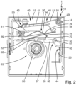
- a switching device 11 according to the invention is shown with a housing 13 or a housing lower part 14.
- An upper housing part is omitted in order to better illustrate the internal structure of the switching device 11.
- the housing lower part 14 has a base 15 and is manufactured in one piece with it, preferably by plastic injection molding. Due to the above-mentioned advantages of the invention with limitation of a maximum temperature in the switching device or its housing 13, in particular due to a heater to be explained in more detail, plastics with lower temperature resistance can be used. For example, this can be PPS, which has a melting point of around 280°C. For lower temperatures, PET with a melting point of around 250°C, PPS with a slightly lower melting point or Bakelite with an even higher melting point can be used. lower temperature of about 150°C, at which the material decomposes. Since PET is considerably cheaper than PPS, significant cost savings can be achieved. In particular, larger quantities of plastic must be used for the housing base 14 and the base 15 or for the entire housing 13.
- the switching device 11 is largely designed as known from the prior art. It has a switch 20, explained at the beginning, which is designed as a so-called snap switch.
- the switch 20 has a switch base 21 made of thin, springy metal, in particular copper sheet, which is attached to a stable wiper 22, preferably riveted or welded in the left area thereof.
- the wiper 22 is made of thick metal and is connected at its left end via the extended switch base 21 to a metallic switching bridge, namely mechanically mounted and electrically contacted. In the right area, the wiper 22 has a wiper projection 23 that protrudes downwards or is bent out.
- the switch 20 has a switching spring arm 24 which is attached to the right free end of the switch base 21, for example welded or riveted.
- the switch 20 is tensioned for the snap function by means of a tensioning arch 26 bent out from the left area of the switching spring arm 24, in that the right free end of the tensioning arch 26 rests or is supported on a hook-shaped support 27 and is thus tensioned.
- the switching spring arm 24 has a switching contact 29 on the left free end. In the state shown here, this rests on a counter contact 31 which is attached to a contact carrier 32. This is the essential closed contact of the switch 20.
- This is used to supply power to, for example, heating devices of an electrical appliance in which the switching device 11 is installed. In particular, these can be heating devices of an electric hob which are operated in a cyclic manner, so that the switching device 11 works in a known manner as a so-called energy regulator.
- energy regulator energy regulator
- a rotary shaft 36 mounted in the housing 13 has a contour disk 37, in particular manufactured in one piece therewith.
- the contour disk 37 runs in a plane perpendicular to the rotary shaft 36 and has a varying radius.
- the aforementioned wiper projection 23 of the wiper 22 or the switch 20 runs in the same plane and is pressed against the outside of the contour disk 37 in a spring-loaded manner.
- the position of the grinder 22 and thus also the position of the support 27 attached to it, for this purpose reference is made to the state of the art.
- the contour disk 37 has a recess 38 which is located in the Fig.1 left directly next to the slider projection 23. This is explained with reference to the Fig.2 discussed in more detail.
- the switching device 11 has an electrothermal triggering device 40, as is also known from the prior art. It mainly has a heating element 41, consisting of a carrier, in particular a ceramic carrier, on the top of which a thick-film heating conductor or other heating conductor is arranged. The heating element 41 is provided on the left with a first electrical connection 43, which goes via the switch base 21 to the same connection as the switch 20.
- Another second electrical connection 44 is provided on the right of the heating element 41.
- a left first contact spring arm 51 of a contact spring 50 is pressed against it with its free end. Since the heating element 41 generally only has low power, for example less than 20 W or even less than 10 W, high currents are not to be expected and the contact spring 50 or the first contact spring arm 51 is therefore sufficient for this. There should also be no switching at this point, but this contact should actually be permanent. It can therefore be designed relatively simply.
- the contact spring 50 is bent out of a round metal wire and is wound in a central region around a bearing projection 54, which is molded onto the housing base 14, for example three to five times.
- the second contact spring arm 53 extends downwards from the central region and rests against a connecting contact 55.
- a lever 60 which has a pivot point 61 in a central region. It is advantageously attached to a bearing on the lower housing part 14 or is mounted so as to be rotatable about the pivot point 61.
- a first lever arm 63 pointing to the left rests on the underside of the right free end of the grinder 22.
- the second lever arm 65 pointing to the right rests against the lower end region of the second contact spring arm 53 or is only very slightly spaced from it.
- the lever 60 is advantageously made of plastic, for example a similar plastic to the housing 13. In any case, it should be electrically insulating.
- the Fig.1 The position shown is one in which the switching device 11 switches a very high, but not yet maximum or continuous power. In this range, heating of the heating element 41 can still cause a bimetallic arm 46 arranged on its underside to move downwards and in doing so press the right-hand free end of the switch base 21 down so far that it runs below the attachment point of the clamping arch 26 on the support 27.
- the switch 20 then switches abruptly and opens switching contact 29 and counter contact 31.
- the energy supply to the heating element 41 then stops, the bimetallic arm 46 moves back again, the right-hand free end of the switch base 21 moves upwards until the switch 20 closes again.
- the heating element 41 is required for the cyclic behavior of the switch 20, so it should not and cannot be switched off. If, however, the rotary shaft 36 is rotated a little further in a clockwise direction, for example by 15°, the slider projection 23 lies exactly in the recess 38, causing the slider 22 to move a little further downwards. In this rotational position, which clearly only covers a very small rotation angle range or is even just a single exact rotational position, the switching device 11 or the switch 20 should be permanently closed. Cyclic switching of the switch 20 is therefore not desired. Furthermore, the dimensioning can be such that the bimetal arm 46 does not bend downwards so far that it can open the switch 20, even after a long time. This should not happen anyway, since the switch 20 should be permanently closed.
- the heating element 41 does not need to be operated, which would only consume unnecessary energy. On the other hand, as explained above, this would generate a relatively large amount of heat, and even with a relatively low output of the heating element 41 itself, this can lead to thermal problems in the housing 13, which is usually closed except for a few ventilation openings.
- the separating device in the form of the lever 60 is used for this purpose. The movement of the slider 22 downwards also moves the left first lever arm 63 downwards, so that the entire lever 60 rotates a little anti-clockwise. The second lever arm 65 rotates with it, comes into contact with the lower area of the second contact spring arm 53 or pushes it away from the connecting contact 55. The triggering device 40 and its heating element 41 are thus switched off, the heating element 41 does not generate unnecessary heat or no heat and does not consume unnecessary energy.
- the switching device 11 or the switch 20 can remain until the rotary shaft 36 is moved or rotated again. If it is rotated slightly anti-clockwise, the slider 22 moves upwards and the lever 60 is released again from the lower area of the second contact spring arm 53. This can then be reattached to the connecting contact 55, the heating element 41 is energized again. If the rotary shaft 36 is rotated clockwise, the wiper 22 is noticeably moved far upwards. This in turn allows the second contact spring arm 53 to rotate the lever 60 via the second lever arm 65, namely clockwise, in order to rest against the connecting contact 55 again.
- the separating device only works exactly in the rotational position of the Fig.2 is active and interrupts the power supply to the heating element 41 or to the triggering device 40.
- the lever 60 can be freely movable and does not have to be coupled to the free end of the slider 22 or to the second contact spring arm 53 in such a way that it inevitably moves with them. This simplifies the design of the lever 60.
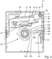
- FIG.3 an alternatively designed switching device 111 is shown, in which the switch 20 and the triggering device 40 are designed as in Fig.1 .
- Only one additional contour disc 37b is required in addition to the contour disc 37a of the Fig.1 and 2
- This further contour disk 37b can be arranged below the contour disk 37a in the embodiment shown here, so that it runs below the slider 22 and does not move it. It is only influenced by the contour disk 37a.
- the contact spring 50 is also designed exactly as in Fig.1 with the two contact spring arms 51 and 53.
- the separating device here has a slider 166, which is made of electrically insulating plastic and is an elongated part. The slider 166 is mounted so that it can be moved longitudinally in a linear guide 167.
- a right end 168 rests against the lower area of the second contact spring arm 53 or is only a short distance away from it.
- a left end 169 extends to just before the flank of a projection 139 on the second contour disk 37b facing it.
- the position of the rotary shaft 36 and the contour disk 37a corresponds to that of Fig.1 , as well as the position of the wiper 22.
- the projection 139 rests on the left end 169 of the slide 166 and pushes it to the right.
- the heating device 11 is thus also permanently deactivated as long as the rotary shaft 36 together with the contour disk 37b remains in this position.
- the switching device 11 of the Fig.3 with a linear movement and not with a rotary movement with a lever.
- the movement of the grinder 22 is not used so that the adjusting device 35 indirectly disconnects the electrical connection to the heating element 41. Rather, the adjusting device 35 disconnects the electrical connection 44 or the connecting contacts 55 and 53 directly via the slide 166.
- the linear guide 167 for the slider 166 can simply be molded onto the base 15.
- the slider 166 can be pushed into the linear guide from the right and then held captive in the linear guide by applying the contact spring 50 or the second contact spring arm 53 pointing downwards.
- FIG.4 A further embodiment of the invention is described in Fig.4 shown.
- the switch 20 and the triggering device 40 are designed as before, so they will not be discussed in more detail.
- This also applies to the first contour disc 37a.
- a second contour disc 37c with a projection 239 is provided, similar to that in Fig.3
- the contact spring 250 also consists of round wire as before, but the second contact spring arm 253 is provided with a U-section 257 pointing to the left in its lower area.
- the two legs of the U-section 257 could also run with a smaller distance from each other.
- This U-section 257 replaces, so to speak, the slider 166 of the Fig.3 It runs until just before the projection 239, the free end of the second contact spring arm 253 is again on the connecting contact 55 as the second electrical connection 44.
- the specially designed contact spring 250 could Fig.4
- a plastic piece can be molded or attached, with which the second contact spring arm 253 rests electrically insulated on the right free end of the wiper 22, similar to the lever 60 with the left lever arm 63 in Fig.1 .
- the downward movement of the slider 22 could also be detected at suitable formed plastic part pushes the lower free end of the contact spring arm 253 away from the connecting contact 55.
Landscapes
- Physics & Mathematics (AREA)
- Electromagnetism (AREA)
- Thermal Sciences (AREA)
- Rotary Switch, Piano Key Switch, And Lever Switch (AREA)
- Breakers (AREA)
Applications Claiming Priority (1)
| Application Number | Priority Date | Filing Date | Title |
|---|---|---|---|
| DE102023200840.8A DE102023200840A1 (de) | 2023-02-02 | 2023-02-02 | Schaltvorrichtung und Verfahren zum Betrieb einer Schaltvorrichtung |
Publications (1)
| Publication Number | Publication Date |
|---|---|
| EP4411774A1 true EP4411774A1 (fr) | 2024-08-07 |
Family
ID=89430345
Family Applications (1)
| Application Number | Title | Priority Date | Filing Date |
|---|---|---|---|
| EP24150044.6A Pending EP4411774A1 (fr) | 2023-02-02 | 2024-01-02 | Dispositif de commutation et procédé de fonctionnement d'un dispositif de commutation |
Country Status (3)
| Country | Link |
|---|---|
| US (1) | US20240266133A1 (fr) |
| EP (1) | EP4411774A1 (fr) |
| DE (1) | DE102023200840A1 (fr) |
Citations (4)
| Publication number | Priority date | Publication date | Assignee | Title |
|---|---|---|---|---|
| DE3813798A1 (de) * | 1988-04-23 | 1989-11-02 | Ego Elektro Blanc & Fischer | Schaltgeraet fuer waermegeraete oder dgl. |
| EP0977224A2 (fr) | 1998-07-29 | 2000-02-02 | E.G.O. ELEKTRO-GERÄTEBAU GmbH | Procédé pour la fabrication d'un interupteur éléctrique |
| DE102008014805A1 (de) * | 2008-03-10 | 2009-03-05 | E.G.O. Elektro-Gerätebau GmbH | Leistungssteuergerät für ein Elektro-Haushaltsgerät und Verfahren zum Betrieb eines Leistungssteuergeräts |
| KR200488089Y1 (ko) * | 2018-08-07 | 2018-12-12 | 주식회사 박전자 | 전기레인지의 온도제어장치 |
Family Cites Families (11)
| Publication number | Priority date | Publication date | Assignee | Title |
|---|---|---|---|---|
| US3869688A (en) * | 1974-01-24 | 1975-03-04 | Westinghouse Electric Corp | Customer adjustment switch assembly |
| DE3639186A1 (de) * | 1986-11-15 | 1988-05-26 | Ego Elektro Blanc & Fischer | Elektro-schaltgeraet, insbesondere zur leistungssteuerung |
| US5021762A (en) * | 1990-08-03 | 1991-06-04 | Robertshaw Controls Company, Inc. | Thermal cycling switch |
| DE69320959T2 (de) * | 1992-06-08 | 1999-01-28 | Strix Ltd., Ronaldsway, Isle of Man | Energieregler |
| US5191310A (en) * | 1992-07-09 | 1993-03-02 | Eaton Corporation | Adjustable cycling switch for electric range |
| US5877670A (en) * | 1997-02-07 | 1999-03-02 | Sehlhorst; Scott B. | Heat motor operated load regulating switch assembly and knob attachment therefor |
| US5847636A (en) * | 1997-02-07 | 1998-12-08 | Sehlhorst; Scott B. | Heat motor operated load regulating switch assembly |
| DE19736308A1 (de) * | 1997-08-21 | 1999-02-25 | Ego Elektro Geraetebau Gmbh | Leistungssteuergerät |
| DE19824871A1 (de) * | 1998-06-04 | 1999-12-09 | Ego Elektro Geraetebau Gmbh | Temperaturschalter, insbesondere einstellbarer Temperaturregler |
| DE10317277A1 (de) * | 2003-04-11 | 2004-10-21 | E.G.O. Elektrogerätebau GmbH | Energiesteuergerät |
| CN111883387B (zh) * | 2020-07-09 | 2024-08-27 | 浙江爱隆电器有限公司 | 一种温控旋钮开关 |
-
2023
- 2023-02-02 DE DE102023200840.8A patent/DE102023200840A1/de active Pending
-
2024
- 2024-01-02 EP EP24150044.6A patent/EP4411774A1/fr active Pending
- 2024-01-08 US US18/406,380 patent/US20240266133A1/en active Pending
Patent Citations (4)
| Publication number | Priority date | Publication date | Assignee | Title |
|---|---|---|---|---|
| DE3813798A1 (de) * | 1988-04-23 | 1989-11-02 | Ego Elektro Blanc & Fischer | Schaltgeraet fuer waermegeraete oder dgl. |
| EP0977224A2 (fr) | 1998-07-29 | 2000-02-02 | E.G.O. ELEKTRO-GERÄTEBAU GmbH | Procédé pour la fabrication d'un interupteur éléctrique |
| DE102008014805A1 (de) * | 2008-03-10 | 2009-03-05 | E.G.O. Elektro-Gerätebau GmbH | Leistungssteuergerät für ein Elektro-Haushaltsgerät und Verfahren zum Betrieb eines Leistungssteuergeräts |
| KR200488089Y1 (ko) * | 2018-08-07 | 2018-12-12 | 주식회사 박전자 | 전기레인지의 온도제어장치 |
Also Published As
| Publication number | Publication date |
|---|---|
| US20240266133A1 (en) | 2024-08-08 |
| DE102023200840A1 (de) | 2024-08-08 |
Similar Documents
| Publication | Publication Date | Title |
|---|---|---|
| EP0194512B2 (fr) | Chauffage électrique pour un bimétal, en particulier pour un régulateur électrique de puissance | |
| DE2625716B2 (de) | Leistungssteuergerät | |
| EP0951040B2 (fr) | Interrupteur à commande thermique | |
| EP0898291B1 (fr) | Appareil de commande de puissance | |
| WO2009012965A1 (fr) | Dispositif de retenue pour une porte d'un appareil électroménager | |
| DE2625715B2 (de) | Leistungssteuergerät | |
| EP4411774A1 (fr) | Dispositif de commutation et procédé de fonctionnement d'un dispositif de commutation | |
| DE69320959T2 (de) | Energieregler | |
| DE2343833B2 (de) | Elektrokochgeraet | |
| DE8617033U1 (de) | Bimetallschalter | |
| DE3610968C2 (de) | Blockiervorrichtung für die Tür einer Waschmaschine, insbesondere einer Haushaltswaschmaschine | |
| EP4151908A1 (fr) | Dispositif de chauffage pour une plaque de cuisson et plaque de cuisson dotée d'un tel dispositif de chauffage | |
| DE2422684A1 (de) | Schnappschalter | |
| WO2008017397A1 (fr) | Dispositif de commutation pour un dispositif de chauffage ainsi que dispositif de chauffage | |
| DE1200413B (de) | Mit Temperaturkompensation arbeitende und thermisch betaetigte elektrische Schaltvorrichtung | |
| DE1806651A1 (de) | Thermostatanordnung,insbesondere fuer selbstreinigende Elektrooefen | |
| EP2387060B1 (fr) | Déclencheur thermique | |
| EP4305654A2 (fr) | Appareil de commande de puissance et agencement d'un tel appareil de commande de puissance équipé d'un dispositif de chauffage électrique | |
| DE1141739B (de) | Energieregler fuer ein elektrisches Heizgeraet | |
| DE2058511B2 (de) | Regler zur Steuerung von Elektrowärmegeräten | |
| EP0557753A2 (fr) | Dispositif de protection d'un appareil | |
| EP0901309A2 (fr) | Regulateur de puissance | |
| DE2150311A1 (de) | Temperaturabhaengiger elektrischer schalter mit einem bimetallischen steuerorgan | |
| DE2264172C3 (de) | Toasterschaltung mit einer wärmeempfindlichen Einrichtung | |
| DE1540914C (de) | Temperaturregeleinnchtung fur eine elektrische Kochplatte mit An koch und Fortkochstufe |
Legal Events
| Date | Code | Title | Description |
|---|---|---|---|
| PUAI | Public reference made under article 153(3) epc to a published international application that has entered the european phase |
Free format text: ORIGINAL CODE: 0009012 |
|
| STAA | Information on the status of an ep patent application or granted ep patent |
Free format text: STATUS: THE APPLICATION HAS BEEN PUBLISHED |
|
| AK | Designated contracting states |
Kind code of ref document: A1 Designated state(s): AL AT BE BG CH CY CZ DE DK EE ES FI FR GB GR HR HU IE IS IT LI LT LU LV MC ME MK MT NL NO PL PT RO RS SE SI SK SM TR |
|
| STAA | Information on the status of an ep patent application or granted ep patent |
Free format text: STATUS: REQUEST FOR EXAMINATION WAS MADE |
|
| 17P | Request for examination filed |
Effective date: 20250207 |