EP4412012A1 - Enceinte sous pression - Google Patents
Enceinte sous pression Download PDFInfo
- Publication number
- EP4412012A1 EP4412012A1 EP23307411.1A EP23307411A EP4412012A1 EP 4412012 A1 EP4412012 A1 EP 4412012A1 EP 23307411 A EP23307411 A EP 23307411A EP 4412012 A1 EP4412012 A1 EP 4412012A1
- Authority
- EP
- European Patent Office
- Prior art keywords
- pressure vessel
- stiffening element
- ribs
- rib
- latch
- Prior art date
- Legal status (The legal status is an assumption and is not a legal conclusion. Google has not performed a legal analysis and makes no representation as to the accuracy of the status listed.)
- Pending
Links
- 239000011324 bead Substances 0.000 claims description 8
- 238000000034 method Methods 0.000 claims description 2
- 238000009434 installation Methods 0.000 description 7
- 239000007789 gas Substances 0.000 description 5
- SFZCNBIFKDRMGX-UHFFFAOYSA-N sulfur hexafluoride Chemical compound FS(F)(F)(F)(F)F SFZCNBIFKDRMGX-UHFFFAOYSA-N 0.000 description 4
- 229960000909 sulfur hexafluoride Drugs 0.000 description 4
- 238000005452 bending Methods 0.000 description 2
- 230000000694 effects Effects 0.000 description 2
- 238000012423 maintenance Methods 0.000 description 2
- 238000004519 manufacturing process Methods 0.000 description 2
- 238000010276 construction Methods 0.000 description 1
- 238000006073 displacement reaction Methods 0.000 description 1
- 239000000463 material Substances 0.000 description 1
- 125000006850 spacer group Chemical group 0.000 description 1
Images




Classifications
-
- H—ELECTRICITY
- H02—GENERATION; CONVERSION OR DISTRIBUTION OF ELECTRIC POWER
- H02B—BOARDS, SUBSTATIONS OR SWITCHING ARRANGEMENTS FOR THE SUPPLY OR DISTRIBUTION OF ELECTRIC POWER
- H02B13/00—Arrangement of switchgear in which switches are enclosed in, or structurally associated with, a casing, e.g. cubicle
- H02B13/02—Arrangement of switchgear in which switches are enclosed in, or structurally associated with, a casing, e.g. cubicle with metal casing
- H02B13/035—Gas-insulated switchgear
- H02B13/045—Details of casing, e.g. gas tightness
-
- H—ELECTRICITY
- H01—ELECTRIC ELEMENTS
- H01H—ELECTRIC SWITCHES; RELAYS; SELECTORS; EMERGENCY PROTECTIVE DEVICES
- H01H9/00—Details of switching devices, not covered by groups H01H1/00 - H01H7/00
- H01H9/02—Bases, casings, or covers
- H01H9/04—Dustproof, splashproof, drip-proof, waterproof, or flameproof casings
-
- H—ELECTRICITY
- H02—GENERATION; CONVERSION OR DISTRIBUTION OF ELECTRIC POWER
- H02B—BOARDS, SUBSTATIONS OR SWITCHING ARRANGEMENTS FOR THE SUPPLY OR DISTRIBUTION OF ELECTRIC POWER
- H02B1/00—Frameworks, boards, panels, desks, casings; Details of substations or switching arrangements
- H02B1/26—Casings; Parts thereof or accessories therefor
- H02B1/30—Cabinet-type casings; Parts thereof or accessories therefor
- H02B1/32—Mounting of devices therein
- H02B1/34—Racks
- H02B1/36—Racks with withdrawable units
-
- H—ELECTRICITY
- H02—GENERATION; CONVERSION OR DISTRIBUTION OF ELECTRIC POWER
- H02B—BOARDS, SUBSTATIONS OR SWITCHING ARRANGEMENTS FOR THE SUPPLY OR DISTRIBUTION OF ELECTRIC POWER
- H02B1/00—Frameworks, boards, panels, desks, casings; Details of substations or switching arrangements
- H02B1/015—Boards, panels, desks; Parts thereof or accessories therefor
-
- H—ELECTRICITY
- H02—GENERATION; CONVERSION OR DISTRIBUTION OF ELECTRIC POWER
- H02B—BOARDS, SUBSTATIONS OR SWITCHING ARRANGEMENTS FOR THE SUPPLY OR DISTRIBUTION OF ELECTRIC POWER
- H02B1/00—Frameworks, boards, panels, desks, casings; Details of substations or switching arrangements
- H02B1/26—Casings; Parts thereof or accessories therefor
- H02B1/30—Cabinet-type casings; Parts thereof or accessories therefor
-
- H—ELECTRICITY
- H02—GENERATION; CONVERSION OR DISTRIBUTION OF ELECTRIC POWER
- H02B—BOARDS, SUBSTATIONS OR SWITCHING ARRANGEMENTS FOR THE SUPPLY OR DISTRIBUTION OF ELECTRIC POWER
- H02B11/00—Switchgear having carriage withdrawable for isolation
- H02B11/02—Details
-
- H—ELECTRICITY
- H02—GENERATION; CONVERSION OR DISTRIBUTION OF ELECTRIC POWER
- H02B—BOARDS, SUBSTATIONS OR SWITCHING ARRANGEMENTS FOR THE SUPPLY OR DISTRIBUTION OF ELECTRIC POWER
- H02B11/00—Switchgear having carriage withdrawable for isolation
- H02B11/12—Switchgear having carriage withdrawable for isolation with isolation by horizontal withdrawal
- H02B11/127—Withdrawal mechanism
- H02B11/133—Withdrawal mechanism with interlock
-
- H—ELECTRICITY
- H02—GENERATION; CONVERSION OR DISTRIBUTION OF ELECTRIC POWER
- H02B—BOARDS, SUBSTATIONS OR SWITCHING ARRANGEMENTS FOR THE SUPPLY OR DISTRIBUTION OF ELECTRIC POWER
- H02B13/00—Arrangement of switchgear in which switches are enclosed in, or structurally associated with, a casing, e.g. cubicle
- H02B13/02—Arrangement of switchgear in which switches are enclosed in, or structurally associated with, a casing, e.g. cubicle with metal casing
- H02B13/035—Gas-insulated switchgear
- H02B13/055—Features relating to the gas
Definitions
- the invention relates to a gas-tight pressure vessel for a switchgear panel of electrical power engineering, in particular medium-voltage engineering, with at least one stiffening element fastened to an outer side of the pressure vessel.
- a switchgear typically comprises individual switchgear panels, which are usually connected via common busbars.
- the individual switchgear panels can comprise gas-tight pressure vessels in which components such as circuit breakers, busbar sections or current and voltage measuring devices for the respective switchgear panel are arranged.
- components such as circuit breakers, busbar sections or current and voltage measuring devices for the respective switchgear panel are arranged.
- switchgear panels are installed close together in a row. For maintenance purposes, it may be necessary to pull the relevant switchgear panel out of the row after it has been disconnected and to push it back into the gap after repair or replacement.
- Pressure vessels have previously been filled with sulphur hexafluoride as an insulating gas to increase the dielectric strength of the switchgear panel.
- sulphur hexafluoride has a high greenhouse potential in addition to a high electrical strength, which is why alternative insulating gases are increasingly being used.
- a pressure vessel regardless of the insulating gas used, can only withstand a limited amount of deformation due to the pressure inside.
- a pressure vessel such as bushings
- components arranged on a pressure vessel can be damaged.
- bulging or bending of pressure vessels in the area of busbar bushings must be prevented, as these usually comprise a rigid plastic material that can be damaged under bending stress.
- the invention is based on the object of creating a pressure vessel with increased mechanical strength, wherein the installation and removal of the pressure vessel is simplified.
- the invention is based on the idea of stiffening parallel spaced outer sides of adjacent pressure vessels by attaching the stiffening element on the one hand to the outside of a pressure vessel and, on the other hand, when the stiffening element is telescoped out, being able to rest against a contact surface on the outside of an adjacent pressure vessel.
- a switch panel with a pressure vessel according to the invention with a telescopically inserted stiffening element can be inserted into a gap between two adjacent switch panels, i.e. next to an adjacent pressure vessel. This can be done particularly easily because the telescopically inserted stiffening element is slightly spaced from the outer wall of the adjacent pressure vessel. The stiffening element can then be telescoped out and locked. In this state, spread between the two outer sides, the stiffening element cannot be telescoped in due to the locking mechanism, whereby both adjacent pressure vessels are stiffened against each other.
- the telescoped stiffening element can also contribute to stiffening the pressure vessel according to the invention.
- the pressure vessel according to the invention simplifies the installation and removal of the adjacent pressure vessel: For the installation and removal of the adjacent pressure vessel, the stiffening element of the pressure vessel according to the invention is telescoped in. Since, due to the stiffening element of the pressure vessel according to the invention, no separate stiffening element, for example in the form of struts, has to be provided on the contact surface of the adjacent pressure vessel to stiffen it, which would otherwise protrude beyond the adjacent pressure vessel, the adjacent pressure vessel can be pushed in and pulled out particularly easily.
- stiffening element is attached outside the pressure vessel according to the invention.
- the pressure vessel according to the invention is stiffened outside, more space is available inside for the respective insulating gas, which increases the dielectric strength of a switchgear panel with the pressure vessel according to the invention.
- the stiffening element can comprise at least one slotted guide and at least one latch which is arranged in the slotted guide.
- the movement of the stiffening element during telescoping and locking is determined by the course of the slotted guide. This makes the stiffening element particularly easy to telescopic and lock and a compact and space-saving arrangement is achieved, which simplifies the installation and removal of the pressure vessel.
- the guide rail can comprise a telescoping section in which the bolt is arranged during telescoping, and at least one locking section in which the bolt is arranged during locking, wherein the bolt and the locking section can be releasably locked together.
- the guide rail can have a U-shaped recess, with two parallel sections of the recess forming a first locking section and a second locking section, which are connected to one another via the telescoping section.
- the stiffening element can be locked particularly easily in two states, namely when it is telescoped out or telescoped in.
- this embodiment also simplifies the installation and removal of the pressure vessel.
- this design of the guide rail allows particularly reliable stiffening, since the wall of the guide rail in the locking sections is oriented perpendicular to a force introduction of the latch.
- the guide rail can be designed in a plane perpendicular to the outside, with the latch being arranged parallel to the outside in the guide rail. This orientation achieves a particularly uniform introduction of force into the stiffening element and reliable stiffening.
- the stiffening element is particularly compact and space-saving.
- the stiffening element can comprise several ribs and/or pairs of ribs spaced parallel to one another. This results in an inherently stiff and at the same time compact structure of the stiffening element in rib construction.
- each pair of ribs can comprise at least one fixed rib, which is oriented perpendicular to the outside and is attached thereto, and at least one rib which is displaceable relative to the fixed rib and which in particular rests against the fixed rib.
- two displaceable ribs and one fixed rib would also be conceivable for each pair of ribs, whereby the displaceable ribs could be arranged on both sides of the fixed rib.
- the vertical orientation achieves a particularly uniform introduction of force into the stiffening element and reliable stiffening.
- the stiffening element is particularly compact and space-saving. In particular, shear forces can be reduced when the displaceable rib rests against the fixed rib.
- At least one rib of the stiffening element can have a guide slot in which a latch is arranged.
- the rib is in particular a rib of a the pairs of ribs described above.
- the slide guide can also be designed like one of the slide guides described above.
- At least one rib of the stiffening element can have an opening in which a latch is received in a form-fitting and/or force-fitting manner.
- the rib can be the rib of the previous embodiment - this would therefore have the slotted guide and the opening - or another rib of one of the pairs of ribs described above.
- the latch of this embodiment can be the latch of the previous embodiment or another latch.
- At least one fixed rib of at least one pair of ribs can have a guide rail in which a latch is arranged, with at least one movable rib of the pair of ribs having an opening in which the latch is received in a form-fitting and/or force-fitting manner.
- the guide rail can be designed in accordance with the guide rails described above.
- the movable rib can be moved relative to the fixed rib via the latch and the guide rail in a space-saving manner in accordance with the course of the guide rail. If the stiffening element is telescoped, the latch is moved in the guide rail.
- At least one movable rib of at least one pair of ribs can have a slotted guide in which a latch is arranged, wherein at least one fixed rib of the pair of ribs has an opening in which the latch is received in a form-fitting and/or force-fitting manner.
- the slotted guide can be designed in accordance with the slotted guides described above. The movable rib is movable relative to the fixed rib via the slotted guide and the latch. guided in a space-saving manner according to the course of the guide rail. If the stiffening element is telescoped, the guide rail is moved on the latch.
- the guide rail and the opening of the movable rib and the fixed rib can be designed in the same way.
- both ribs can be the same components, which also simplifies the manufacture of the stiffening element.
- the stiffening element can comprise a fixed profile part with at least one bead, which is fastened to the outside and to which the fixed ribs are fastened, wherein the outer contours of the fixed ribs are adapted to the cross-sectional shape of the fixed profile part.
- the stiffening element is easily fastened, in particular welded, to the outside of the pressure vessel via the fixed profile part.
- the fixed profile part has an additional stiffening effect and a reliable and uniform introduction of force into the stiffening element takes place.
- At least one passage can be formed between the fixed profile part and the outside and/or between the fixed profile part and all the fixed ribs, which passage is intended to be able to guide a functional component of the switch panel through the passage of the stiffening element.
- a passage can be formed, for example, by the bead of the fixed profile part and/or a recess on all the fixed ribs.
- the stiffening element can comprise a displaceable profile part with at least one bead, which is attached to the displaceable Ribs are attached, in particular welded, with the outer contours of the movable ribs being adapted to the cross-sectional shape of the movable profile part.
- the stiffening element can be attached, in particular screwed, in a simple manner via the movable profile part to an outer side of a second pressure vessel arranged adjacent to it at a distance D, which is parallel to the outer side. This considerably simplifies the installation and removal of the pressure vessel according to the invention and of the adjacent second pressure vessel, since only the attachment of the movable profile part has to be released, after which the stiffening element can be telescoped.
- the movable profile part has a stiffening effect in addition to the rib arrangement and ensures reliable and uniform force introduction into the stiffening element.
- the movable ribs can, for example, come into direct contact with the adjacent outer side or a mounting plate attached to it.
- the latch can be designed as a rod or bolt that extends in an axial direction, wherein the ends of the latch can each be provided with a securing device, in particular a nut and/or a split pin, whereby the latch is secured against axial movement.
- the rod is advantageously guided through all of the ribs involved, whereby the stiffening element is designed to be particularly simple, compact and space-saving.
- the rod through ensures that the force is introduced into the stiffening element evenly. If, for example, only individual screw connections were provided that connect the ribs of the individual rib pairs to one another, the force would be introduced less evenly.
- the stiffening element can comprise at least three component sets with different components, wherein each of the three component sets comprises at least two identical components, in particular with identical shape.
- all bars, all ribs and all profile parts of the stiffening element can each represent a component set.
- all bars and/or all ribs and/or all profile parts of the stiffening element can each have an identical shape. This reduces the number of different components of the stiffening element, making production simpler and more cost-effective.
- the pressure vessel can have a cable connection compartment, a busbar compartment and a circuit breaker compartment.
- the invention relates to an arrangement comprising a first pressure vessel according to the invention and a second pressure vessel arranged adjacent thereto at a distance D, on the outside of which, spaced parallel to and opposite the outside of the first pressure vessel, a mounting plate is fastened, on which the stiffening element of the first pressure vessel is mounted.
- the invention relates to a switchgear panel for electrical power engineering, in particular medium-voltage engineering, with a pressure vessel according to the invention.
- the invention relates to an arrangement comprising a first switch panel with a pressure vessel according to the invention and a second switch panel arranged adjacent thereto at a distance D with a second pressure vessel, on the outer side of which, spaced parallel to and opposite the outer side of the pressure vessel of the first switch panel, a mounting plate is fastened to which the stiffening element of the first pressure vessel is mounted.
- At least one separately formed sword can be provided, which rests on the outer sides of the pressure vessels and has an engagement projection which engages in the stiffening element, whereby the sword additionally blocks the stiffening element.
- the invention relates to a method for stiffening a pressure vessel according to the invention, which is arranged in a switch panel, wherein the switch panel is arranged parallel and spaced apart from an adjacent second switch panel with a second pressure vessel, comprising the following steps: transferring the stiffening element into the telescoped state, locking the stiffening element, and fastening the stiffening element to the second pressure vessel.
- Fig.1 shows an arrangement of a first pressure vessel 11 according to the invention and a second pressure vessel 11' arranged adjacent thereto at a distance D as a possible embodiment of the invention.
- the pressure vessel 11 comprises a cable connection space 21 in order to connect a switchgear panel with the pressure vessel to a power network, a busbar space 17 in order to distribute the energy of a connected phase, and a circuit breaker space 19 in order to selectively connect a connected phase to a busbar or to disconnect it from it.
- a stiffening element 15 is attached to an outer side 23 of the pressure vessel 11, which can be telescoped and locked perpendicular to the outer side 23, wherein the stiffening element 15 in Fig.1 is telescoped in.
- a mounting plate 13 is attached to the outside 23' of the pressure vessel 11', which is parallel to the outside 23 of the first pressure vessel 11 and opposite and spaced apart from it.
- the mounting plate 13 can have several recesses for its stiffening.
- the stiffening element 15 of the first pressure vessel 11 can be attached to the mounting plate 13, in particular screwed on, in order to stiffen the pressure vessel 11 and the second pressure vessel 11' against each other.
- the pressure vessel 11 and the second pressure vessel 11' are usually provided with a low-voltage cabinet, which forms part of a switchgear panel.
- the typical outer contour of the respective low-voltage cabinet is shown in Fig.1 illustrated by the dashed boxes at the level of the busbar compartment 17.
- the clearance corresponding to the distance D is extremely small, so that a stiffening element that would be attached instead of the mounting plate 13 and would protrude further beyond the pressure vessel 11' would hit the low-voltage cabinet of the pressure vessel 11 when the second pressure vessel 11' was pulled out (out of the plane of the drawing) or pushed in (into the plane of the drawing).
- a normal stiffening element attached to the pressure vessel 11 instead of the stiffening element 15 could also make it more difficult to pull out or push in the pressure vessel 11 or the pressure vessel 11', since it could become jammed and would therefore have to be dismantled at great expense.
- stiffening element 15 is telescopic and, when telescoped in, does not protrude beyond the pressure vessel 11, both the pressure vessel 11 and the pressure vessel 11' can be pulled out or pushed in without the stiffening element 15 becoming jammed.
- the stiffening element 15 can also be attached to other locations on the pressure vessel 11 according to the invention.
- the stiffening element 15 is made of Fig.1 shown in a detailed view.
- the stiffening element 15 comprises a fixed profile part 25, with which the stiffening element 15 is welded to the outside 23 of the pressure vessel 11.
- the stiffening element 15 of the exemplary embodiment comprises six identical pairs of ribs 33 that are parallel and spaced apart from one another.
- Each pair of ribs 33 has a fixed rib 27 and a movable rib 29 that rests against the fixed rib 27 and is movable relative to it.
- Each fixed rib 27 is welded to the fixed profile part 25, and a movable profile part 31 is welded to each movable rib 29.
- Fig.2 is the stiffening element 15 is telescoped out, locked and the movable profile part 31 is screwed to the mounting plate 13.
- Each rib 27, 29 has a guide 35 and an opening 41 (in Fig. 2 not visible). Both the ribs 27, 29 and the slotted guides 35 are each formed in a plane perpendicular to the outer side 23, whereby all ribs 27, 29 are identical components.
- the fixed profile part 25 and the movable profile part 31 can also be two identical components.
- the ribs 27, 29 of each rib pair 33 are oriented such that a bar 39 in the form of a rod can be inserted through the slotted guide 35 of one rib 27, 29 of each rib pair 33 and the opening 41 of the other rib 29, 27 of the respective rib pair 33, whereby the two bars 39 can be two identical components. Furthermore, the two bars 39 are each arranged parallel to the outer side 23 in the respective slotted guides 35.
- Each latch 39 is received in the respective openings 41 in a form-fitting manner, so that the movable ribs 29 together with the movable profile part 31 can be moved relative to the fixed ribs 27 along the path predetermined by the course of the link guides 35.
- the ends of the respective latch 39 are each provided with a securing device in the form of a nut 37 to prevent axial displacement of the latch 39.
- the fixed profile part 25 comprises a cross-sectional shape 47 with two beads 43, which can have a different width and serve to stiffen the profile part 25.
- the beads 43 also form a passage 45 through which a functional component 57 ( Fig.5 ) of the switch panel can be guided through the stiffening element 15.
- a functional component 57 Fig.5
- Fig.3 one of the ribs 27, 29 with the slotted guide 35 and the opening 41 is shown in a detailed view by way of example.
- the slotted guide 35 comprises a locking section 53 and a locking section 53', wherein the respective latch 39 consists of Fig. 2 and the respective locking sections 53, 53' can be detachably locked together.
- a telescopic section 55 is provided which connects the locking sections 53, 53' to one another.
- the movable ribs 29 can be lifted, for example by a fitter, so that the respective latch 39 is lifted out of the respective locking sections 53, 53', whereby the stiffening element 15 can be telescoped.
- the link guide 35 can, for example, have a U-shaped recess that is formed in the respective rib 27, 29, with two parallel sections of the link guide 35 forming a first locking section 53 and a second locking section 53', which are connected to one another via a telescopic section 55.
- This design of the link guide allows for particularly reliable stiffening, since the wall of the link guide in the locking sections 53, 53' is oriented perpendicular to a force introduction of the latch 39.
- the rib 27, 29 also has an outer contour 49 which is adapted to the cross-sectional shape 47 of the profile part 25, 31.
- the rib 27, 29 has a recess 51. All ribs 27, 29 of the stiffening element 15 are according to Fig.4 and therefore each have the recess 51, whereby a passage 45 ( Fig.2 ) is trained.
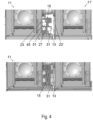
- a detailed view of a pressure vessel 11 is shown next to an adjacent pressure vessel 11', wherein the stiffening element 15 is telescoped in and locked.
- a passage 45 which passes through the recesses 51 of all fixed ribs 27 is formed, a displaceable profile part 31 and a mounting plate 13 are provided which is welded to an outer side 23' of the pressure vessel 11' which is spaced parallel to the outer side 23 of the pressure vessel 11 and opposite.
- Fig.4 In the illustration below of Fig.4 is the arrangement of the upper representation of Fig.4 with the stiffening element 15 telescoped out, wherein the stiffening element 15 is locked and the movable profile part 31 is screwed to the mounting plate 13.
- Fig.5 a detailed view of a pressure vessel 11 is shown next to an adjacent pressure vessel 11', wherein the stiffening element 15 is telescoped in and locked.
- a passage 45 is formed, through which a functional component 57 of the control panel is guided through the stiffening element 15.
- Fig.6 a detailed view of a pressure vessel 11 is shown next to an adjacent pressure vessel 11', with the stiffening element 15 telescoped out and locked.
- a movable profile part 31 of the stiffening element 15 is screwed to a mounting plate 13 of the pressure vessel 11'.
- Two swords 59 are inserted between the two pressure vessels 11, 11', each of which rests against both pressure vessels 11, 11'. This allows the swords 59 to serve as spacers on the one hand, while on the other hand additional stiffening can be achieved by the swords 59.
- each sword 59 has an engagement projection 61 which engages in the stiffening element 15, whereby each sword 59 additionally blocks the stiffening element 15.
- each sword 59 has a cross plate 63, via which the sword 59 is screwed to the two pressure vessels 11, 11'.
Landscapes
- Engineering & Computer Science (AREA)
- Power Engineering (AREA)
- Pressure Vessels And Lids Thereof (AREA)
- Driving Mechanisms And Operating Circuits Of Arc-Extinguishing High-Tension Switches (AREA)
Applications Claiming Priority (1)
| Application Number | Priority Date | Filing Date | Title |
|---|---|---|---|
| DE102023102362.4A DE102023102362A1 (de) | 2023-01-31 | 2023-01-31 | Druckbehälter |
Publications (1)
| Publication Number | Publication Date |
|---|---|
| EP4412012A1 true EP4412012A1 (fr) | 2024-08-07 |
Family
ID=89619523
Family Applications (1)
| Application Number | Title | Priority Date | Filing Date |
|---|---|---|---|
| EP23307411.1A Pending EP4412012A1 (fr) | 2023-01-31 | 2023-12-28 | Enceinte sous pression |
Country Status (4)
| Country | Link |
|---|---|
| US (1) | US20240258044A1 (fr) |
| EP (1) | EP4412012A1 (fr) |
| CN (1) | CN118431926A (fr) |
| DE (1) | DE102023102362A1 (fr) |
Citations (4)
| Publication number | Priority date | Publication date | Assignee | Title |
|---|---|---|---|---|
| JP2000059930A (ja) * | 1998-08-13 | 2000-02-25 | Meidensha Corp | ガス絶縁開閉装置 |
| DE10314458A1 (de) * | 2003-03-28 | 2004-10-07 | Alstom | Metallgekapselte gasisolierte Schaltanlage |
| JP6710922B2 (ja) * | 2015-09-25 | 2020-06-17 | 日新電機株式会社 | スイッチギヤ及びスイッチギヤのガス封入方法 |
| EP3745548A1 (fr) * | 2019-05-29 | 2020-12-02 | Schneider Electric Industries SAS | Récipient à isolation par gaz |
Family Cites Families (2)
| Publication number | Priority date | Publication date | Assignee | Title |
|---|---|---|---|---|
| DE10032797A1 (de) * | 2000-06-28 | 2002-01-10 | Siemens Ag | Angularkompensator für die Kapselung oder den rohrförmigen Außenleiter einer gasisolierten Hochspannungsanlage |
| DE202010006779U1 (de) * | 2010-05-06 | 2010-08-05 | Siemens Aktiengesellschaft | Angularkompensator |
-
2023
- 2023-01-31 DE DE102023102362.4A patent/DE102023102362A1/de active Pending
- 2023-12-28 EP EP23307411.1A patent/EP4412012A1/fr active Pending
-
2024
- 2024-01-26 US US18/423,701 patent/US20240258044A1/en active Pending
- 2024-01-30 CN CN202410126028.3A patent/CN118431926A/zh active Pending
Patent Citations (4)
| Publication number | Priority date | Publication date | Assignee | Title |
|---|---|---|---|---|
| JP2000059930A (ja) * | 1998-08-13 | 2000-02-25 | Meidensha Corp | ガス絶縁開閉装置 |
| DE10314458A1 (de) * | 2003-03-28 | 2004-10-07 | Alstom | Metallgekapselte gasisolierte Schaltanlage |
| JP6710922B2 (ja) * | 2015-09-25 | 2020-06-17 | 日新電機株式会社 | スイッチギヤ及びスイッチギヤのガス封入方法 |
| EP3745548A1 (fr) * | 2019-05-29 | 2020-12-02 | Schneider Electric Industries SAS | Récipient à isolation par gaz |
Also Published As
| Publication number | Publication date |
|---|---|
| DE102023102362A1 (de) | 2024-08-01 |
| CN118431926A (zh) | 2024-08-02 |
| US20240258044A1 (en) | 2024-08-01 |
Similar Documents
| Publication | Publication Date | Title |
|---|---|---|
| EP1856709B1 (fr) | Commutateur electromecanique | |
| AT394284B (de) | Sicherheitslastschaltleiste (einbauleiste) | |
| EP1829178A1 (fr) | Dispositif de fixation rapide sur un appareil d'installation electrique | |
| EP0000711B1 (fr) | Contacteur avec bornes de raccordement librement accessibles et disposées dans des plans différents | |
| DE10153109C2 (de) | Traggestell für einen elektrischen Schalter | |
| EP0228987B1 (fr) | Dispositif de verrouillage d'un appareil commutateur monté d'une façon déplaçable | |
| DE102023102362A1 (de) | Druckbehälter | |
| EP0624939A1 (fr) | Dispositif de contact pour interrupteurs de puissance rétractables dans des installations de distribution | |
| EP1570505B1 (fr) | Disjoncteur basse tension | |
| EP2208269B1 (fr) | Dispositif de protection empechant le contact avec des conducteurs electriques dans une unite de distribution electrique | |
| EP0202192B1 (fr) | Installation haute tension blindée à isolation à gaz sous pression | |
| DE2949774C3 (de) | Betätigungs- und Verriegelungsvorrichtung für eine Schaltanlage | |
| DE69834897T2 (de) | Verwechslungsschutzanordnung für elektrische Schaltgeräte, insbesondere für Leistungsschalter und Differenzstromschutzschalter | |
| DE2434364C2 (de) | Lastumschalter mit ueberschaltwiderstaenden fuer stufenschalter von stufentransformatoren | |
| DE527559C (de) | Sicherung von aus Trenn- und OElschaltern bestehenden Schaltanlagen | |
| EP0634051B1 (fr) | Disjoncteur multipolaire a basse tension avec arbre de commande | |
| EP0492754B1 (fr) | Dispositif de support pour appareils d'installation électrique | |
| DE2515153C3 (de) | Schaltschrank mit einem aus Profilschienen hergestellten Gerüst | |
| DE2533343C3 (de) | Verriegelung für eine Schalterkombination mit Trennschaltern und einem Leistungsschalter | |
| EP2237303B1 (fr) | Unité de fusible pour un panneau d'interrupteurs d'une installation de commutation électrique, notamment d'une installation de commutation de moyenne tension à air isolé | |
| DE882443C (de) | Verriegelung einer Schaltung fuer Sammelschienen | |
| EP3109882B1 (fr) | Dispositif de verrouillage | |
| DE3536764A1 (de) | Schaltfeld fuer eine elektrische mittelspannungsschalt- und -verteileranlage | |
| DE1276174B (de) | Einrichtung zur mechanischen Verriegelung von Leistungsschaltern und Trennschaltern bei Systemen mit mehr als zwei Sammelschienen | |
| DE1955169A1 (de) | Lasttrenner |
Legal Events
| Date | Code | Title | Description |
|---|---|---|---|
| PUAI | Public reference made under article 153(3) epc to a published international application that has entered the european phase |
Free format text: ORIGINAL CODE: 0009012 |
|
| STAA | Information on the status of an ep patent application or granted ep patent |
Free format text: STATUS: THE APPLICATION HAS BEEN PUBLISHED |
|
| AK | Designated contracting states |
Kind code of ref document: A1 Designated state(s): AL AT BE BG CH CY CZ DE DK EE ES FI FR GB GR HR HU IE IS IT LI LT LU LV MC ME MK MT NL NO PL PT RO RS SE SI SK SM TR |
|
| STAA | Information on the status of an ep patent application or granted ep patent |
Free format text: STATUS: REQUEST FOR EXAMINATION WAS MADE |
|
| 17P | Request for examination filed |
Effective date: 20241227 |