EP4412253A1 - Dispositif auditif intra-auriculaire avec élément protecteur de microphone - Google Patents
Dispositif auditif intra-auriculaire avec élément protecteur de microphone Download PDFInfo
- Publication number
- EP4412253A1 EP4412253A1 EP23154414.9A EP23154414A EP4412253A1 EP 4412253 A1 EP4412253 A1 EP 4412253A1 EP 23154414 A EP23154414 A EP 23154414A EP 4412253 A1 EP4412253 A1 EP 4412253A1
- Authority
- EP
- European Patent Office
- Prior art keywords
- microphone
- protector element
- sound port
- housing
- end portion
- Prior art date
- Legal status (The legal status is an assumption and is not a legal conclusion. Google has not performed a legal analysis and makes no representation as to the accuracy of the status listed.)
- Pending
Links
Images





Classifications
-
- H—ELECTRICITY
- H04—ELECTRIC COMMUNICATION TECHNIQUE
- H04R—LOUDSPEAKERS, MICROPHONES, GRAMOPHONE PICK-UPS OR LIKE ACOUSTIC ELECTROMECHANICAL TRANSDUCERS; ELECTRIC HEARING AIDS; PUBLIC ADDRESS SYSTEMS
- H04R25/00—Electric hearing aids
- H04R25/65—Housing parts, e.g. shells, tips or moulds, or their manufacture
- H04R25/652—Ear tips; Ear moulds
- H04R25/654—Ear wax retarders
-
- H—ELECTRICITY
- H04—ELECTRIC COMMUNICATION TECHNIQUE
- H04R—LOUDSPEAKERS, MICROPHONES, GRAMOPHONE PICK-UPS OR LIKE ACOUSTIC ELECTROMECHANICAL TRANSDUCERS; ELECTRIC HEARING AIDS; PUBLIC ADDRESS SYSTEMS
- H04R2225/00—Details of deaf aids covered by H04R25/00, not provided for in any of its subgroups
- H04R2225/025—In the ear hearing aids [ITE] hearing aids
-
- H—ELECTRICITY
- H04—ELECTRIC COMMUNICATION TECHNIQUE
- H04R—LOUDSPEAKERS, MICROPHONES, GRAMOPHONE PICK-UPS OR LIKE ACOUSTIC ELECTROMECHANICAL TRANSDUCERS; ELECTRIC HEARING AIDS; PUBLIC ADDRESS SYSTEMS
- H04R2460/00—Details of hearing devices, i.e. of ear- or headphones covered by H04R1/10 or H04R5/033 but not provided for in any of their subgroups, or of hearing aids covered by H04R25/00 but not provided for in any of its subgroups
- H04R2460/17—Hearing device specific tools used for storing or handling hearing devices or parts thereof, e.g. placement in the ear, replacement of cerumen barriers, repair, cleaning hearing devices
Definitions
- the invention relates to an ITE ("in the ear") hearing device comprising a housing to be worn at least in part in the ear canal of a user and including an outer portion oriented towards the exterior of the user's ear when the housing is worn least in part in the ear canal of the user, and a microphone accommodated in the housing, the outer portion of the housing comprising a sound port for allowing ambient sound to reach the microphone.
- ITE in the ear
- a microphone protector element may be provided which is removably inserted into an outwardly oriented outer aperture of the sound port so as to cover the sound port for preventing ingress of cerumen towards the microphone.
- Such microphone protector elements may comprise, for example, a plurality of small holes, see, e.g., EP 1 439 733 B1 , a membrane, see. e.g., WO 2008/154954 A1 , or a plurality of small holes and a membrane, see, e.g., US 2009/014978 A1 .
- the outer aperture of the sound port may be oriented laterally so that it is actually covered in the outward direction, thereby preventing ingress of cerumen towards the microphone from the outward direction, see, e.g., DE 197 06 306 C1 , US 202/0135127 A1 and EP 3 123 743 B1 .
- an ITE hearing device as defined in claims 1 and 9, respectively, a microphone protector element as defined in claim 10, an assembly with a tool as defined in claim 11, and a method as defined in claims 13, 14 and 15, respectively.
- ITE hearing device herein refers to a device supporting hearing activity in general which is to be worn at least in part in the ear canal of a user.
- the hearing device may be used to improve the hearing capability or communication capability of a user, for instance by compensating a hearing loss of a hearing-impaired user, in which case the hearing device is commonly referred to as a hearing instrument such as a hearing aid, or hearing prosthesis.
- a hearing device may also be used to output sound based on an audio signal which may be communicated by a wire or wirelessly to the hearing device.
- a hearing device may also be used to reproduce a sound in a user's ear canal received by a microphone.
- the reproduced sound may be amplified to account for a hearing loss, such as in a hearing instrument, or may be output without accounting for a hearing loss, for instance to provide for a faithful reproduction of detected ambient sound and/or to add sound features of an augmented reality in the reproduced ambient sound, such as in a hearable.
- a hearing device may also provide for a situational enhancement of an acoustic scene, e.g. beamforming and/or active noise cancelling (ANC), with or without amplification of the reproduced sound.
- ITE hearing devices configured to be worn at least in part in the ear canal of a user include earbuds, hearables, and hearing instruments such as in-the-ear (ITE) hearing aids.
- the invention is beneficial in that, by providing the sound port element with a trough for collecting cerumen, efficient protection of the microphone from cerumen can be achieved.
- the invention is further beneficial in that, by providing the microphone protector element with a trough for collecting cerumen or by providing the microphone protector element with an inner end portion extending towards the bottom of the trough of the sound port so as to guide residual cerumen into the trough, collected cerumen can be easily removed from the ITE hearing device when removing the microphone protector element.
- the inner end portion may be provided with a bottom plate which helps collecting and removing the cerumen. Where there is no bottom plate, surfaces of the inner end portion extending towards the bottom of the trough may serve as a guiding surface for the cerumen to flow into the trough.
- the invention is still further beneficial in that, by providing an assembly comprising a tool and a microphone protector element which is fixed at the front end of the tool via a connection with at least one predetermined breaking point, the microphone protector element can be easily and conveniently inserted into the sound port.
- the invention is also beneficial in that, by providing the microphone protector element with a plurality of holes and inserting a pin-like tip of a tool into one of the holes, the microphone protector element can be easily and conveniently removed from the sound port.
- the invention is also beneficial in that, by providing the microphone protector element with a plurality of holes and by providing a punching tool comprising a plurality of pins, each of which conforms with one of the holes of the microphone protector element, the microphone protector element can be easily cleaned from cerumen.
- the outer surface of the outer end portion of the microphone protector element may be flush with the outer surface of the outer portion of the housing.
- the outer end portion of the microphone protector element may have a plate-like shape; in particular, the outer end portion of the microphone protector element may have a shape of a flat elongate plate.
- the outer end portion of the microphone protector element may have a banana-like curvature.
- the thickness of the outer end portion of the microphone protector element may be from 0.3 to 1.5 mm.
- the outer end portion of the microphone protector element may comprise a plurality of holes, such as 3 to 12 holes, for allowing ambient sound to pass through the outer end portion.
- the holes may be located above the trough.
- the holes may have a diameter between 0.2 and 0.9 mm.
- the holes may be arranged one after the other along a curved line.
- the outer end portion of the microphone protector element may comprise a grid or a fur for allowing ambient sound to pass through the outer end portion of the microphone protector element.
- the grid or fur may form only a part of the outer surface of the outer end portion of the microphone protector element.
- the outer end portion of the microphone protector element may comprise a cavity in a region above the trough so that the thickness of the outer end portion of the microphone protector element is reduced in this region.
- the inner end portion of the microphone protector element may comprise a plate-like element which conforms with the bottom of the trough.
- the plate-like element of the inner end portion of the microphone protector element may be an integral part of the microphone protector element.
- the plate-like element of the inner end portion of the microphone protector element may be a separate part fixed to an intermediate section of the inner end portion of the microphone protector element.
- the outer end portion and the plate-like element of the inner end portion of the microphone protector element may be connected via at least two column-like connector portions.
- the outer end portion and the plate-like element of the inner end portion of the microphone protector element may be connected via a first connector portion provided at one lateral end of the microphone protector element and via a second connector portion provided at an opposite lateral end of the microphone protector element, wherein the lateral opening extends between the first and second connector portion.
- the microphone protector element may be detachably held within the sound port by elastic forces; in particular, the microphone protector element may be made of an elastic material having an elasticity of at least 0.5 %.
- the microphone protector element may be made of at least one of metals, plastics, elastomers and ceramics.
- a microphone grid may be provided laterally off-set relative to the trough below the lateral opening of the microphone protector element to protect the microphone from residual cerumen having passed through the microphone protector element.
- the ITE hearing device may further comprise a second one of the microphone protector element inserted in an outer aperture of a second sound port.
- the housing may comprise a shell, wherein the outer end portion of the housing comprises a faceplate fixed at the shell for closing the shell at the side oriented towards the exterior of the user's ear, wherein the sound port is provided in the faceplate.
- the ITE hearing device is an ITE hearing aid comprising such a shell and faceplate with the sound port in the faceplate.
- the microphone protector element may be made of an elastic material and may comprise a plurality of holes for allowing ambient sound to pass through the microphone protector element towards the microphone(22), wherein a second end of the tool opposite to the first end may comprise a pin-like tip (72) for being inserted into one of the holes so that the microphone protector element when having been detachably inserted into the outer aperture of the sound port is removable from the sound port by withdrawing the tool with the microphone protector element held be elastic forces on the pin-like tip.
- the microphone protector element may be provided at the insertion tool via injection molding.
- the microphone protector element may have an elongate shape with two opposite lateral end portions, wherein the connection to the insertion tool may be formed by two bar-like elements, each extending from another one of the two lateral end portions of the microphone protector element to the insertion tool.
- the bar-like elements may be curved.
- the hole into which the pin-like tip of the insertion tool is inserted may have a diameter from 0.2 mm to 0.9 mm.
- Fig. 1 is an elevated view of a first example of a faceplate 10 of a hearing device embodied as an ITE hearing aid with two symmetrically arranges sound ports 12, each covered by a microphone protector element 14 which is removably inserted into the respective sound port 12 (for illustrative purposes the left-hand microphone protector element 14 is omitted in Fig. 1 ).
- the faceplate 10 further comprises a pushbutton 16 for manual operation of the hearing aid by the user and a central circular element 18 with a central pin, which serve as electrical contact surfaces.
- Fig. 2 is a perspective view of the faceplate 10 of Fig. 1 , wherein the microphone protector elements 14 are shown, for illustrative purposes, in a position during insertion into or removal from the respective sound port 12.
- the faceplate 10 is part of the outer (i.e., outwardly oriented portion) of the housing of the ITE hearing aid and is fixed at a shell of the housing for closing the shell at the side oriented towards the exterior of the user's ear canal when the ITE hearing aid is worn in the ear canal.
- Fig. 3 is a perspective, partially cut-away view of the faceplate 10 of Figs. 1 and 2 , which shows one of the microphone protector elements 14, when inserted into the sound port 12, in more detail.
- the sound port 12 is provided for allowing ambient sound 20 to reach a microphone 22 located within the housing of the hearing aid.
- the microphone protector element 14 is inserted into an outer aperture 24 of the sound port 12 so as to cover the sound port for inhibiting ingress of cerumen 26 towards the microphone 20.
- the sound port 12 comprises a trough 28 for collecting residual cerumen 26 having passed through the microphone protector element 14 in a collection space 30, with the microphone 20 being laterally off-set with regard to the trough 28 and being separated from the collection space 30 of the trough by a lateral wall 32 (hereinafter, "laterally” or “lateral” indicates a direction which is transverse/perpendicular of a direction in which sound enters the sound port 12 through the microphone protector element 14; in case that the outer portion of the housing is formed by a faceplate such lateral direction is essentially parallel to a general plane of the faceplate 10, i.e. roughly transverse to a direction essentially perpendicular to a general plane of the face plate).
- the microphone protector element 14 comprises an outer end portion 34 for covering the outer aperture 24 of the sound port 12 and an inner end portion 36 extending towards the bottom 38 of the trough 28 into the collection space 30, wherein the microphone protector element 14 forms a lateral opening 40 between the outer end portion 34 and the inner end portion 36 for allowing sound to propagate towards the microphone 22.
- the sound port 12, in particular its backwall 39 opposite to the lateral opening 40 cooperates with the microphone protector element 14, in particular its lateral opening 40, to direct sound towards the microphone 22.
- the lateral wall 32 of the trough 28 covers part of the lateral opening 40.
- a microphone grid 42 is provided laterally off-set relative to the trough 28 below the lateral opening 40 of the microphone protector element and the lateral wall 32 of the trough 28 to protect the microphone 22 from residual cerumen having passed through the microphone protector element 14.
- the outer surface 44 of the outer end portion 34 of the microphone protector element 14 is flush with the outer surface 46 of the faceplate 10. Such flush arrangement prevents the user's "blind" finger from confusing the microphone protector element 14 with the pushbutton 16, so that operation of the pushbutton is facilitated and inadvertent pollution of the microphone protector element 14 by the user's finger is reduced.
- the microphone protector element 14 may have a dark color so as to conceal pollution / contamination of the microphone protector element 14.
- the outer end portion 34 of the microphone protector element 14 may have a plate-like flat shape, with a thickness of for example, from 0.15 mm to 0.8 mm.
- the outer end portion 34 of the microphone protector element 14 may have a shape of a flat elongate plate, such as a reniform shape.
- the outer end portion 34 of the microphone protector element 14 may have a banana-like curvature, as shown in Figs. 1 and 2 .
- the outer end portion 34 of the microphone protector element 14 comprises a plurality of holes 48 for allowing ambient sound to pass through the outer end portion 34, with the holes 48 being arranged one after the other along a curved line.
- the holes 48 may have a diameter between 0.2 mm and 0.9 mm. While in the example five of the holes 48 are shown, there may be a larger or a smaller number of holes 48, such as from 3 to 12.
- the holes 48 are located above the trough 28, so that residual cerumen passing through one of the holes 48 is collected within the collection space of the trough 28.
- the microphone 22, which is laterally off-set with regard to the trough is also laterally off-set with regard to the holes 48, so that a labyrinth-type structure is created wherein the lateral wall 32 of the trough 28 prevents the direct ingress of cerumen towards the microphone 22.
- the lateral off-set of the microphone 22 relative to the holes is beneficial in that thereby the microphone is protected from damages by thin objects which may pass through the holes 48, such as needles or bristles.
- a cerumen collection trough 28 which is lateral off-set with regard to the microphone 22 allows for less frequent replacement of the microphone protector element 14, thereby enhancing user comfort.
- the longer sound path formed by the labyrinth-type structure through the lateral opening extends the usage time of the microphone 22, and its protection is extended.
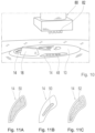
- the microphone protector element 14 is provided with a plurality of holes 48 for allowing ambient sound to pass through the microphone protector element 14, the holes 48 could be replaced by other structures, such as a grid 50 or a fur 52 (artificial or natural), which allow ambient sound to pass through the outer end portion 34 of the microphone protector element 14, as schematically illustrated in Figs. 11A-C .
- the grid 50 or fur 52 may cover substantially the entire the outer surface of the outer end portion of the microphone protector element ( Fig. 11A, C ) or only part of it ( Fig. 11B ). It is to be understood that the grid 50 or fur 52 covers a sound opening (not shown in Figs. 11A-C ) extending through the outer end portion 34 of the microphone protector element 14.
- Figs. 4A and B illustrate an example of how to insert the microphone protector element 14 into the sound port 12, wherein there is provided an assembly comprising an insertion tool 60 carrying at its front end 62 the microphone protector element 14 which is fixed at the front end 62 of the insertion tool 60 via a connection 64 with at least one predetermined breaking point.
- the microphone protector element 14 is inserted into the outer aperture of the sound port 12 by moving the insertion tool 60 accordingly until the outer end portion 34 of the microphone protector element 14 is flush with the outer surface 46 of the faceplate 10 ( Fig. 4A ).
- the insertion tool 60 is tilted relative to the inserted microphone protector element 14 so as to the detach the insertion tool 60 from the microphone protector element 14 by breaking the connection 64 at the at least one predetermined breaking point.
- the insertion tool 60 is removed ( Fig. 4B ).
- the insertion tool 60 may have a shape similar to a pencil or rod.
- the microphone protector element 14 may be provided at the insertion tool 60 via injection molding; in particular, the insertion tool 60 and the microphone protector element 14 may be integrally formed as one piece by an injection molding process.
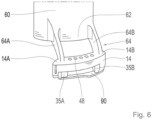
- the microphone protector element 14 has an elongate shape with two opposite lateral end portions 14A, 14B, wherein the connection 64 to the insertion tool 60 is formed by two bar-like elements 64A, 64B, each extending from another one of the two lateral end portions of the microphone protector element to the insertion tool 60.
- the bar-like elements 64A, 64B may be curved, as shown in Fig. 4A .
- both microphone protector elements 14 may be provided, at the correct mutual distance given be by the distance of the two sound ports 12, at the insertion tool 60, so as to allow for simultaneous insertion into two sound ports 12.
- Providing the microphone protector element(s) 14 at the tip of an insertion tool 60 facilitates handling of the microphone protector elements 14 during insertion into the sound port 12; in particular, the need for using a microscope my be eliminated thereby.
- the microphone protector element 14 After insertion the microphone protector element 14 is detachably held within the sound port 12 by elastic forces.
- the microphone protector element 14 may be made of an elastic material having an elasticity of at least 0.5 %; in particular, the microphone protector element 14 may be made of at least one of metals, plastics, elastomers and ceramics.
- the walls of the sound port 12 and/or the microphone protector element 14 may be provided with press ribs.
- the dimensions of the sound port 12 and/or the microphone protector element 14 are selected for providing press fit of the microphone protector element 14 within the sound port 12.
- FIGs. 9A-C An example of how the microphone protector element 14 may be removed, for replacement, from the sound port 12 is illustrated in Figs. 9A-C , wherein a pin-like tip 72 of a removal tool 70 is inserted into one of the holes 48 ( Fig. 9B ) and then the microphone protector element 14 is removed from the sound port 12 by withdrawing the removal tool 70 with the microphone protector element 14 held be elastic forces on the pin-like tip 72 ( Fig. 9C ).
- the hole 48 into which the pin-like tip 72 of the removal tool 70 is inserted may have the same diameter as the other holes 48, or its diameter may deviate from that of the other holes; for example, the hole 48 may have a diameter from 0.2 mm to 0.9 mm.
- the removal tool 70 may have a shape similar to a pencil or rod.
- the insertion tool 60 and the removal tool 70 may be combined into a single combined tool wherein one of the two opposite end portions is formed by the insertion tool 60 carrying at its end the microphone protector element 14 and the other end portion is formed by the removal tool 70 having at its end the pin-like tip 72.
- the combined tool can be used as a removal tool by inserting the pin-like tip 72 into one of the holes 48 for removing again the microphone protector element 14 when necessary.
- FIG. 10 An example of how the microphone protector element 14 may be cleaned, while remaining inserted within the sound port 12, is schematically illustrated in Fig. 10 , wherein a punching tool 80 is provided which comprises a plurality of pins 82, each of which conforms with one of the holes 48 of the microphone protector element 14.
- the pins 82 of the punching tool 80 are inserted into the holes 48 of the microphone protector element 14 so as to free the holes 48 from cerumen, with the displaced cerumen being collected by the trough 48. Finally, the pins 82 of the punching tool 80 are withdrawn from the holes 48 of the microphone protector element 14.
- the punching tool 80 provides for a convenient and efficient way of cleaning the microphone protector element 14 without a need to remove the microphone protector element 14 from the sound port 12.
- the inner end portion 36 of microphone protector element 14 is fully open towards bottom 38 of the trough 28, with a column-like element 35A, 35B provided at each of the lateral end portions 14A, 14B extending into the trough 28 towards the bottom 38 of the trough 28 so as to guide residual cerumen into the trough 28, wherein surfaces of the column-like elements 35A,B may serve as a guiding surface for the cerumen to flow into the trough 28.
- the inner end portion 36 of the microphone protector element 14 may comprise a plate-like element 90 extending along the bottom 38 of the trough 28 so as to collect residual cerumen in the trough 28.
- the plate-like element 90 may conform with the bottom 38 of the trough.
- the microphone protector element 14 when being removed from the sound port 12, provides for removal of most or all of the residual cerumen collected within the trough 28, thereby facilitating cleaning of the sound port 12.
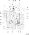
- the plate-like element 90 of the inner end portion 36 of the microphone protector element may be a separate part, such as a plate, fixed to an intermediate section of the inner end portion 36 of the microphone protector element 14 formed by the column-like elements 35A,B, as illustrated in Figs. 5 and 6 , wherein Fig. 6 , similar to Fig. 4A , shows an assembly comprising an insertion tool 60 carrying at its front end 62 the microphone protector element 14 which is fixed at the front end 62 of the insertion tool 60 via a connection 64 with at least one predetermined breaking point, and wherein Fig. 5 , like Fig. 3 , shows the microphone protector element 14 after having been inserted into the sound port 12.
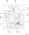
- the plate-like element 90 of the inner end portion 36 of the microphone protector element 14 may be an integral part of the microphone protector element 14, as illustrated in Figs 7 and 8 , wherein Fig. 8 , similar to Fig. 4A , shows an assembly comprising an insertion tool 60 carrying at its front end 62 the microphone protector element 14 which is fixed at the front end 62 of the insertion tool 60 via a connection 64 with at least one predetermined breaking point, and wherein Fig. 7 , like Fig. 3 , shows the microphone protector element 14 after having been inserted into the sound port 12.,
- the outer end portion 34 and the plate-like element 90 of the microphone protector element 14 may be connected via at least two column-like connector portions 35A,35B, preferably each one provided at one of the lateral end portions 14A, 14B, respectively.
- the outer end portion 34 and plate-like element 90 of the inner end portion 36 of the microphone protector element 14 are connected via a first connector portion 35A provided at one lateral end 14A of the microphone protector element 14 and via a second connector portion 35B provided at the opposite lateral end 14B of the microphone protector element 14, so that a lateral opening 40 of the microphone protector element 14 oriented towards the microphone 22 extends between the first and second connector portion 35A, 35B.
- the outer end portion 34 of the microphone protector element 14 comprises a cavity 54 in a region above the trough 28 so that the thickness of the outer end portion 34 of the microphone protector element 14 is reduced in this region.
- the trough 28 is implemented as part of the sound port 12
- the trough could be implemented by the inner end portion of the microphone protector element, as a modification of the examples of Figs. 5 to 8 , i.e., the inner end portion 36 could be formed as a trough.
- the sound ports with the microphone protection elements have been provided in faceplate, in alternative implementations the sound ports with the microphone protection elements could be provided in the shell (in case the shell has a portion which is oriented towards the exterior of the user's ear when the shell is worn in the ear canal or, more generally, the sound ports with the microphone protection elements could be provided in an outer portion of the housing oriented towards the exterior of the user's ear when the shell is worn in the ear canal.
Landscapes
- Engineering & Computer Science (AREA)
- Manufacturing & Machinery (AREA)
- Health & Medical Sciences (AREA)
- General Health & Medical Sciences (AREA)
- Neurosurgery (AREA)
- Otolaryngology (AREA)
- Physics & Mathematics (AREA)
- Acoustics & Sound (AREA)
- Signal Processing (AREA)
- Details Of Audible-Bandwidth Transducers (AREA)
Priority Applications (1)
| Application Number | Priority Date | Filing Date | Title |
|---|---|---|---|
| EP23154414.9A EP4412253A1 (fr) | 2023-02-01 | 2023-02-01 | Dispositif auditif intra-auriculaire avec élément protecteur de microphone |
Applications Claiming Priority (1)
| Application Number | Priority Date | Filing Date | Title |
|---|---|---|---|
| EP23154414.9A EP4412253A1 (fr) | 2023-02-01 | 2023-02-01 | Dispositif auditif intra-auriculaire avec élément protecteur de microphone |
Publications (1)
| Publication Number | Publication Date |
|---|---|
| EP4412253A1 true EP4412253A1 (fr) | 2024-08-07 |
Family
ID=85158652
Family Applications (1)
| Application Number | Title | Priority Date | Filing Date |
|---|---|---|---|
| EP23154414.9A Pending EP4412253A1 (fr) | 2023-02-01 | 2023-02-01 | Dispositif auditif intra-auriculaire avec élément protecteur de microphone |
Country Status (1)
| Country | Link |
|---|---|
| EP (1) | EP4412253A1 (fr) |
Citations (9)
| Publication number | Priority date | Publication date | Assignee | Title |
|---|---|---|---|---|
| DE19706306C1 (de) | 1997-02-18 | 1998-10-08 | Siemens Audiologische Technik | Im Ohr tragbares Hörhilfegerät |
| DE10104129A1 (de) * | 2001-01-29 | 2002-08-14 | Olaf E A Greiner | Hörgerät und Filtereinheit für ein solches |
| WO2008154954A1 (fr) | 2007-06-18 | 2008-12-24 | Phonak Ag | Couvercle pour ouvertures de boîtier de microdispositif électrique |
| US20090014978A1 (en) | 2007-07-12 | 2009-01-15 | Shumway David L | Mounted, multi-angle, extendable step |
| EP1439733B1 (fr) | 2004-02-10 | 2011-01-12 | Phonak Ag | Protection de microphones pour des prothèses auditives |
| US20160165334A1 (en) * | 2014-12-03 | 2016-06-09 | Knowles Electronics, Llc | Hearing device with self-cleaning tubing |
| US20160165368A1 (en) * | 2014-12-05 | 2016-06-09 | Jay Stewart | Wax relief pathway for hearing aid sound inlet |
| EP3123743B1 (fr) | 2014-03-24 | 2019-01-02 | Sonova AG | Prothèse auditive ite, et procédé de fabrication correspondant |
| US20200135127A1 (en) | 2018-10-25 | 2020-04-30 | Samsung Electronics Co., Ltd. | Display apparatus of multi display system and control method thereof |
-
2023
- 2023-02-01 EP EP23154414.9A patent/EP4412253A1/fr active Pending
Patent Citations (9)
| Publication number | Priority date | Publication date | Assignee | Title |
|---|---|---|---|---|
| DE19706306C1 (de) | 1997-02-18 | 1998-10-08 | Siemens Audiologische Technik | Im Ohr tragbares Hörhilfegerät |
| DE10104129A1 (de) * | 2001-01-29 | 2002-08-14 | Olaf E A Greiner | Hörgerät und Filtereinheit für ein solches |
| EP1439733B1 (fr) | 2004-02-10 | 2011-01-12 | Phonak Ag | Protection de microphones pour des prothèses auditives |
| WO2008154954A1 (fr) | 2007-06-18 | 2008-12-24 | Phonak Ag | Couvercle pour ouvertures de boîtier de microdispositif électrique |
| US20090014978A1 (en) | 2007-07-12 | 2009-01-15 | Shumway David L | Mounted, multi-angle, extendable step |
| EP3123743B1 (fr) | 2014-03-24 | 2019-01-02 | Sonova AG | Prothèse auditive ite, et procédé de fabrication correspondant |
| US20160165334A1 (en) * | 2014-12-03 | 2016-06-09 | Knowles Electronics, Llc | Hearing device with self-cleaning tubing |
| US20160165368A1 (en) * | 2014-12-05 | 2016-06-09 | Jay Stewart | Wax relief pathway for hearing aid sound inlet |
| US20200135127A1 (en) | 2018-10-25 | 2020-04-30 | Samsung Electronics Co., Ltd. | Display apparatus of multi display system and control method thereof |
Similar Documents
| Publication | Publication Date | Title |
|---|---|---|
| US8467556B2 (en) | Canal hearing device with disposable battery module | |
| EP2238772B1 (fr) | Appareil auditif modulaire | |
| JP4708645B2 (ja) | 長期装着式耳管型補聴器 | |
| DK2625871T3 (en) | Hearing aid | |
| EP2238773B1 (fr) | Appareil auditif à paroi constituée d'une carte à circuit imprimé | |
| DK2443842T3 (en) | Hearing aid with a replaceable insert cap | |
| US20100086158A1 (en) | Open tip for hearing aid | |
| US9247360B2 (en) | Hearing instrument housing having a plug-in connection, plug and hearing instrument | |
| CN104469642B (zh) | 过滤件 | |
| US9049526B2 (en) | Compact programming block connector for hearing assistance devices | |
| CN109756833B (zh) | 听力设备 | |
| US9961458B1 (en) | Hearing aid sleeve | |
| US7466836B2 (en) | Removal tool for in situ cerumen removal from hearing devices | |
| EP4622294A1 (fr) | Protection de port acoustique et port acoustique intra-auriculaire | |
| EP1880573B1 (fr) | Appareil auditif cic | |
| EP4412253A1 (fr) | Dispositif auditif intra-auriculaire avec élément protecteur de microphone | |
| EP3123743B1 (fr) | Prothèse auditive ite, et procédé de fabrication correspondant | |
| US20130077808A1 (en) | Ite hearing instrument with programming connector | |
| EP3148222A1 (fr) | Barriere en elastomere pour protection contre la cire d'oreille pour porte acoustique d'aide auditive | |
| US11638108B2 (en) | Canal hearing devices with sound port contaminant guards | |
| EP2309779B1 (fr) | Appareil auditif et oreillette | |
| WO2001043500A1 (fr) | Embout conforme pour un appareil de correction auditive | |
| US9185503B2 (en) | Domes for a receiver-in-the-canal hearing instrument | |
| DK2238773T3 (en) | Hearing aid with a wall formed by a printed circuit board | |
| US20190045310A1 (en) | In-the-ear-hearing-device |
Legal Events
| Date | Code | Title | Description |
|---|---|---|---|
| PUAI | Public reference made under article 153(3) epc to a published international application that has entered the european phase |
Free format text: ORIGINAL CODE: 0009012 |
|
| STAA | Information on the status of an ep patent application or granted ep patent |
Free format text: STATUS: THE APPLICATION HAS BEEN PUBLISHED |
|
| AK | Designated contracting states |
Kind code of ref document: A1 Designated state(s): AL AT BE BG CH CY CZ DE DK EE ES FI FR GB GR HR HU IE IS IT LI LT LU LV MC ME MK MT NL NO PL PT RO RS SE SI SK SM TR |
|
| STAA | Information on the status of an ep patent application or granted ep patent |
Free format text: STATUS: REQUEST FOR EXAMINATION WAS MADE |
|
| 17P | Request for examination filed |
Effective date: 20250203 |