EP4412353A1 - Verfahren und vorrichtung zur bestimmung eines zeitfensters sowie endgerät und speichermedium - Google Patents
Verfahren und vorrichtung zur bestimmung eines zeitfensters sowie endgerät und speichermedium Download PDFInfo
- Publication number
- EP4412353A1 EP4412353A1 EP22874836.4A EP22874836A EP4412353A1 EP 4412353 A1 EP4412353 A1 EP 4412353A1 EP 22874836 A EP22874836 A EP 22874836A EP 4412353 A1 EP4412353 A1 EP 4412353A1
- Authority
- EP
- European Patent Office
- Prior art keywords
- time window
- terminal
- information
- configuration information
- uplink transmission
- Prior art date
- Legal status (The legal status is an assumption and is not a legal conclusion. Google has not performed a legal analysis and makes no representation as to the accuracy of the status listed.)
- Pending
Links
Images



Classifications
-
- H—ELECTRICITY
- H04—ELECTRIC COMMUNICATION TECHNIQUE
- H04B—TRANSMISSION
- H04B7/00—Radio transmission systems, i.e. using radiation field
- H04B7/02—Diversity systems; Multi-antenna system, i.e. transmission or reception using multiple antennas
- H04B7/04—Diversity systems; Multi-antenna system, i.e. transmission or reception using multiple antennas using two or more spaced independent antennas
- H04B7/06—Diversity systems; Multi-antenna system, i.e. transmission or reception using multiple antennas using two or more spaced independent antennas at the transmitting station
- H04B7/0686—Hybrid systems, i.e. switching and simultaneous transmission
- H04B7/0695—Hybrid systems, i.e. switching and simultaneous transmission using beam selection
- H04B7/06952—Selecting one or more beams from a plurality of beams, e.g. beam training, management or sweeping
-
- H—ELECTRICITY
- H04—ELECTRIC COMMUNICATION TECHNIQUE
- H04L—TRANSMISSION OF DIGITAL INFORMATION, e.g. TELEGRAPHIC COMMUNICATION
- H04L25/00—Baseband systems
- H04L25/02—Details ; arrangements for supplying electrical power along data transmission lines
-
- H—ELECTRICITY
- H04—ELECTRIC COMMUNICATION TECHNIQUE
- H04L—TRANSMISSION OF DIGITAL INFORMATION, e.g. TELEGRAPHIC COMMUNICATION
- H04L5/00—Arrangements affording multiple use of the transmission path
-
- H—ELECTRICITY
- H04—ELECTRIC COMMUNICATION TECHNIQUE
- H04L—TRANSMISSION OF DIGITAL INFORMATION, e.g. TELEGRAPHIC COMMUNICATION
- H04L5/00—Arrangements affording multiple use of the transmission path
- H04L5/0001—Arrangements for dividing the transmission path
- H04L5/0003—Two-dimensional division
- H04L5/0005—Time-frequency
- H04L5/0007—Time-frequency the frequencies being orthogonal, e.g. OFDM(A) or DMT
- H04L5/0012—Hopping in multicarrier systems
-
- H—ELECTRICITY
- H04—ELECTRIC COMMUNICATION TECHNIQUE
- H04L—TRANSMISSION OF DIGITAL INFORMATION, e.g. TELEGRAPHIC COMMUNICATION
- H04L5/00—Arrangements affording multiple use of the transmission path
- H04L5/003—Arrangements for allocating sub-channels of the transmission path
- H04L5/0048—Allocation of pilot signals, i.e. of signals known to the receiver
-
- H—ELECTRICITY
- H04—ELECTRIC COMMUNICATION TECHNIQUE
- H04L—TRANSMISSION OF DIGITAL INFORMATION, e.g. TELEGRAPHIC COMMUNICATION
- H04L5/00—Arrangements affording multiple use of the transmission path
- H04L5/003—Arrangements for allocating sub-channels of the transmission path
- H04L5/0048—Allocation of pilot signals, i.e. of signals known to the receiver
- H04L5/0051—Allocation of pilot signals, i.e. of signals known to the receiver of dedicated pilots, i.e. pilots destined for a single user or terminal
-
- H—ELECTRICITY
- H04—ELECTRIC COMMUNICATION TECHNIQUE
- H04W—WIRELESS COMMUNICATION NETWORKS
- H04W56/00—Synchronisation arrangements
- H04W56/004—Synchronisation arrangements compensating for timing error of reception due to propagation delay
- H04W56/0045—Synchronisation arrangements compensating for timing error of reception due to propagation delay compensating for timing error by altering transmission time
-
- H—ELECTRICITY
- H04—ELECTRIC COMMUNICATION TECHNIQUE
- H04W—WIRELESS COMMUNICATION NETWORKS
- H04W72/00—Local resource management
- H04W72/04—Wireless resource allocation
-
- H—ELECTRICITY
- H04—ELECTRIC COMMUNICATION TECHNIQUE
- H04W—WIRELESS COMMUNICATION NETWORKS
- H04W72/00—Local resource management
- H04W72/04—Wireless resource allocation
- H04W72/044—Wireless resource allocation based on the type of the allocated resource
- H04W72/0446—Resources in time domain, e.g. slots or frames
-
- H—ELECTRICITY
- H04—ELECTRIC COMMUNICATION TECHNIQUE
- H04W—WIRELESS COMMUNICATION NETWORKS
- H04W72/00—Local resource management
- H04W72/12—Wireless traffic scheduling
- H04W72/1263—Mapping of traffic onto schedule, e.g. scheduled allocation or multiplexing of flows
- H04W72/1268—Mapping of traffic onto schedule, e.g. scheduled allocation or multiplexing of flows of uplink data flows
-
- H—ELECTRICITY
- H04—ELECTRIC COMMUNICATION TECHNIQUE
- H04W—WIRELESS COMMUNICATION NETWORKS
- H04W72/00—Local resource management
- H04W72/20—Control channels or signalling for resource management
- H04W72/23—Control channels or signalling for resource management in the downlink direction of a wireless link, i.e. towards a terminal
-
- H—ELECTRICITY
- H04—ELECTRIC COMMUNICATION TECHNIQUE
- H04W—WIRELESS COMMUNICATION NETWORKS
- H04W52/00—Power management, e.g. Transmission Power Control [TPC] or power classes
- H04W52/04—Transmission power control [TPC]
- H04W52/06—TPC algorithms
- H04W52/14—Separate analysis of uplink or downlink
- H04W52/146—Uplink power control
-
- H—ELECTRICITY
- H04—ELECTRIC COMMUNICATION TECHNIQUE
- H04W—WIRELESS COMMUNICATION NETWORKS
- H04W52/00—Power management, e.g. Transmission Power Control [TPC] or power classes
- H04W52/04—Transmission power control [TPC]
- H04W52/38—TPC being performed in particular situations
Definitions
- This application pertains to the field of communications technologies, and specifically relates to a time window determination method and apparatus, a terminal, and a storage medium.
- demodulation reference signal bundling (Demodulation Reference Signal bundling, DMRS bundling) is enabled for an uplink repetition (repetition)
- a DMRS bundling time window is configured based on continuous physical slots (physical slots), and user equipment (User Equipment, UE) within the time window is expected to maintain an uplink transmission with power consistency and phase continuity.
- UE User Equipment
- Embodiments of this application provide a time window determination method and apparatus, a terminal, and a storage medium to resolve a problem that a terminal cannot maintain an uplink transmission with power consistency and phase continuity within a DMRS bundling time window.
- a time window determination method includes:
- a time window determination apparatus includes:
- a terminal includes a processor, a memory, and a program or instructions stored in the memory and executable on the processor. When the program or instructions are executed by the processor, the steps of the method according to the first aspect are implemented.
- a terminal includes a processor and a communication interface.
- the processor is configured to determine at least one second time window based on first information and a first time window, where the first time window is a configured demodulation reference signal bundling DMRS bundling time window, the second time window is an actual DMRS bundling time window, an uplink transmission within the actual DMRS bundling time window is a transmission that meets a first condition, and the first condition includes maintaining power consistency and phase continuity.
- a readable storage medium stores a program or instructions. When the program or instructions are executed by a processor, the steps of the method according to the first aspect are implemented.
- a chip includes a processor and a communication interface.
- the communication interface is coupled to the processor.
- the processor is configured to run a program or instructions to implement the method according to the first aspect.
- a computer program or program product is provided.
- the computer program or program product is stored in a non-transitory storage medium.
- the program or program product is executed by at least one processor to implement the steps of the time window determination method according to the first aspect.
- the terminal can determine the at least one second time window based on the first information and the first time window, where the second time window is the actual DMRS bundling time window, thereby ensuring that even if some configurations or signaling makes an uplink resource unavailable, the uplink transmission can still meet "maintaining power consistency and phase continuity" within the actual DMRS bundling time window. This further facilitates joint channel estimation at a receive end based on the second time window, improves accuracy of channel estimation, and improves a coverage capability.
- first, second, and the like in this specification and claims of this application are used to distinguish between similar objects instead of describing a specified order or sequence. It should be understood that the terms used in this way are interchangeable in appropriate circumstances, so that the embodiments of this application can be implemented in other orders than the order illustrated or described herein.
- objects distinguished by “first” and “second” usually fall within one class, and a quantity of objects is not limited. For example, there may be one or more first objects.
- the term “and/or” in the specification and claims indicates at least one of connected objects, and the character “/" generally represents an "or” relationship between associated objects.
- technologies described in the embodiments of this application are not limited to a long term evolution (Long Term Evolution, LTE)/LTE-Advanced (LTE-Advanced, LTE-A) system, and can also be used in other wireless communications systems, such as code division multiple access (Code Division Multiple Access, CDMA), time division multiple access (Time Division Multiple Access, TDMA), frequency division multiple access (Frequency Division Multiple Access, FDMA), orthogonal frequency division multiple access (Orthogonal Frequency Division Multiple Access, OFDMA), single-carrier frequency-division multiple access (Single-carrier Frequency-Division Multiple Access, SC-FDMA), and other systems.
- code division multiple access Code Division Multiple Access
- TDMA time division multiple access
- FDMA frequency division multiple access
- OFDMA Orthogonal frequency division multiple access
- SC-FDMA single-carrier Frequency-Division Multiple Access
- system and “network” in the embodiments of this application are usually used interchangeably.
- the described technologies may be used for the foregoing systems and radio technologies, and may also be used for other systems and radio technologies.
- the new radio (New Radio, NR) system is described for an illustrative purpose, and NR terms are used in most of the following descriptions.
- NR New Radio
- 6G 6th Generation
- FIG. 1 is a structural diagram of a wireless communications system to which an embodiment of this application may be applied.
- the wireless communications system includes a terminal 11 and a network-side device 12.
- the terminal 11 may also be referred to as a terminal device or user terminal (User Equipment, UE).
- UE User Equipment
- the terminal 11 may be a terminal-side device such as a mobile phone, a tablet personal computer (Tablet Personal Computer), a laptop computer (Laptop Computer) or a notebook computer, a personal digital assistant (Personal Digital Assistant, PDA), a palmtop computer, a netbook, an ultra-mobile personal computer (ultra-mobile personal computer, UMPC), a mobile Internet device (Mobile Internet Device, MID), an augmented reality (augmented reality, AR) or virtual reality (virtual reality, VR) device, a robot, a wearable device (Wearable Device), a vehicular device (VUE), a pedestrian terminal (PUE), or a smart home (a home device having a wireless communication function, such as a refrigerator, a television, a washing machine, or furniture).
- a terminal-side device such as a mobile phone, a tablet personal computer (Tablet Personal Computer), a laptop computer (Laptop Computer) or a notebook computer, a personal digital assistant (Personal Digital Assistant, PDA), a palmtop computer,
- the wearable device includes a smartwatch, a smart band, a smart headphone, smart glasses, smart jewelry (a smart bracelet, a smart wrist chain, a smart ring, a smart necklace, a smart anklet, a smart ankle chain, or the like), a smart wristband, smart clothing, a game console, or the like. It should be noted that a specific type of the terminal 11 is not limited in the embodiments of this application.
- the network-side device 12 may be a base station or a core network.
- the base station may be referred to as a NodeB, an evolved NodeB, an access point, a base transceiver station (Base Transceiver Station, BTS), a radio base station, a radio transceiver, a basic service set (Basic Service Set, BSS), an extended service set (Extended Service Set, ESS), a home NodeB, a home evolved NodeB, a WLAN access point, a Wi-Fi node, a transmission and reception point (Transmission and Reception Point, TRP), or another appropriate term in the art.
- BTS Base Transceiver Station
- BSS Basic Service Set
- Extended Service Set Extended Service Set
- ESS extended service set
- a home NodeB a home evolved NodeB
- WLAN access point a Wi-Fi node
- TRP Transmission and Reception Point
- UE can maintain power consistency and phase continuity in a process of transmitting multiple physical uplink shared channels (Physical Uplink Shared Channel, PUSCH). Then in a case that a network-side device receives the multiple PUSCHs, the network-side device can obtain, based on a demodulation reference signal (Demodulation Reference Signal, DMRS) of one PUSCH, channel information transmitted in other PUSCHs.
- DMRS Demodulation Reference Signal
- the DMRS in the multiple PUSCHs can be used for joint channel estimation to improve reception performance. This technology is referred to as DMRS bundling.
- multiple PUSCHs herein may be different repetitions in same PUSCH scheduling, or may be transmissions over multiple slots TBoMS (TB over Multiple Slots) in same PUSCH scheduling, or may be PUSCHs in different PUSCH scheduling.
- a DMRS bundling time window (Time domain window, TDW) is defined as duration within which UE is expected to maintain power consistency and phase continuity among multiple PUSCH transmissions, so that a receive end performs joint channel estimation within the time window.
- An uplink transmission with power consistency and phase continuity means that at least the following conditions should be met among multiple uplink transmissions:
- FIG. 2 is a schematic flowchart of a time window determination method according to an embodiment of this application. As shown in FIG. 2 , the method includes: Step 201: A terminal determines at least one second time window based on first information and a first time window.
- the first time window is a configured demodulation reference signal bundling DMRS bundling time window
- the second time window is an actual DMRS bundling time window
- an uplink transmission within the actual DMRS bundling time window is a transmission that meets a first condition
- the first condition includes maintaining power consistency and phase continuity.
- an actual DMRS bundling time window can be obtained through division within the first time window, to ensure that the uplink transmission with power consistency and phase continuity is maintained within the second time window.
- the first time window may be a configured demodulation reference signal bundling DMRS bundling time window, and one first time window may include one or more second time windows.
- the configured DMRS bundling time window may be a configured time domain window.
- the configured DMRS bundling time window may be a nominal time domain window.
- the second time window may be an actual DMRS bundling time window, and the UE can maintain the transmission with power consistency and phase continuity within the second time window.
- the second time window may be a sub DMRS bundling time window (sub-window), and the UE can maintain the transmission with power consistency and phase continuity within the second time window.
- sub-window sub DMRS bundling time window
- the first information may indicate an event that may result in inability to maintain power consistency and/or phase continuity.
- the first information may be beam switching configuration information, used to instruct the terminal to perform beam switching.
- the first information may be configuration information of a physical downlink control channel PDCCH monitoring occasion, used to instruct the terminal to perform PDCCH monitoring on the physical downlink control channel PDCCH monitoring occasion.
- the first information may be information related to some transmission gaps, used to indicate transmission gaps.
- the first information may be frequency hopping interval information, used to indicate a frequency hopping interval.
- the first information may be precoder cycling granularity configuration information, used to indicate a precoder cycling granularity.
- the first information may be power adjustment signaling (e.g. transmit power command), used to instruct the terminal to perform a power adjustment.
- power adjustment signaling e.g. transmit power command
- the first information may be timing advance TA adjustment signaling, used to instruct the terminal to perform a TA adjustment.
- the terminal may determine, based on the first information, to divide the first time window, and further determine the at least one second time window based on the first time window.
- the UE may determine, based on the first information, not to divide the first time window, that is, the first time window does not need to be divided, and further may determine that the first time window coincides with the second time window.
- the UE may determine, based on the first information, that a manner of dividing the first time window is division processing, where the division processing may determine one second time window from the first time window. After determining one second time window that can meet the first condition, the UE may further determine, based on a terminal capability and the first information, whether to perform division again within the first time window to obtain a second time window that meets the first condition.
- the first information may be indicated to the terminal by the network-side device, or determined based on a protocol predefinition, or preset.
- the transmission that meets the first condition may be a transmission meeting power consistency and phase continuity.
- the terminal can determine the at least one second time window based on the first information and the first time window, where the second time window is the actual DMRS bundling time window, thereby ensuring that even if some configurations or signaling makes an uplink resource unavailable, the uplink transmission can still meet "maintaining power consistency and phase continuity" within the actual DMRS bundling time window. This further facilitates joint channel estimation at a receive end based on the second time window, improves accuracy of channel estimation, and improves a coverage capability.
- a terminal determines at least one second time window based on first information and a first time window includes either of the following:
- the UE may determine, based on the first information, that the transmission with power consistency and phase continuity can be maintained within the first time window, further determine that the first time window does not need to be divided, and may determine that the second time window coincides with the first time window.
- the UE may determine, based on the first information, that the transmission with power consistency and phase continuity cannot be maintained within the first time window, and further may determine that the first time window needs to be divided at least once, so that the first time window includes one second time window, to ensure that the transmission with power consistency and phase continuity is maintained, that is, the at least one second time window can be determined within the first time window.
- the terminal can determine, based on the first information, whether the first condition is met within the first time window. If the first condition is met, the terminal can determine that the first time window coincides with the second time window. If the first condition is not met, the terminal can determine the at least one second time window.
- the terminal determines the at least one second time window within the first time window in a case that the terminal determines, based on the first information, that the first condition is not met within the first time window includes:
- the UE may determine, based on the first information, that the transmission with power consistency and phase continuity can be maintained within a slot between the start moment of the first time window and the first moment, and may further determine that the 1-st second time window is from the start moment of the first time window to the first moment.
- the UE may determine not to restart a new second time window after the 1-st second time window.
- the UE may determine to restart a new second time window after the 1-st second time window.
- the terminal can determine the 1-st second time window based on the first information, and can further determine all the second time windows except the 1-st second time window.
- the terminal determines all second time windows except the 1-st second time window within the first time window in a case that the terminal is capable of restarting a new second time window after one second time window includes:
- the first event is an event that causes the first condition not to be met within the first time window.
- the UE may determine the last second time window by using a first uplink available slot or symbol after a first event as a start moment and the end moment of the first time window as an end moment.
- the UE may determine a plurality of second time windows within the first time window.
- the terminal determines one of the other second time windows by using a first uplink available slot or symbol after a 1-st first event as a start moment and a next first event as an end moment, and so on, thereby determining all the second time windows within the first time window, where the last second time window within the first time window uses a first uplink available slot or symbol after a last first event as a start moment and the end moment of the first time window as an end moment.
- the terminal in a case that the terminal is capable of restarting a new second time window after one second time window, the terminal may determine at least one second time window again after determining the 1-st second time window.
- the terminal determines, based on the first information, that the first condition is not met within the first time window includes:
- the terminal determines that the terminal receives the first information and that the first information includes the first target information, it may be considered that the terminal will perform events indicated by the first target information, and these events will cause inability to maintain the uplink transmission with power consistency and phase continuity. Consequently, demodulation performance of joint channel estimation at the receive end is affected, and the coverage capability is ultimately reduced. Therefore, in a case that the terminal determines that the terminal receives the first information and that the first information includes the first target information, the terminal determines that the first condition is not met within the first time window. In this case, the terminal may determine the at least one second time window within the first time window. In other words, the terminal may divide the first time window into one or more second time windows to ensure that the transmission with power consistency and phase continuity is maintained within the second time window.
- the terminal may determine that the first condition is not met within the first time.
- the terminal may determine that the first condition is not met within the first time.
- a PDCCH skipping indication instructs the UE to skip PDCCH monitoring within a period of time. Therefore, if there is an occasion (occasion) requiring the UE to perform PDCCH monitoring within the first time window, the terminal may determine the at least one second time window within the first time window. In other words, the terminal may divide the first time window into one or more second time windows.
- the terminal may determine that the first condition is not met within the first time.
- the terminal may determine the at least one second time window within the first time window. In other words, the terminal may divide the first time window into one or more second time windows.
- the terminal may determine that the first condition is not met within the first time.
- the terminal may determine the at least one second time window within the first time window. In other words, the terminal may divide the first time window into one or more second time windows.
- the terminal may determine that the first condition is not met within the first time.
- the terminal may determine the at least one second time window within the first time window. In other words, the terminal may divide the first time window into one or more second time windows.
- the terminal may determine that the first condition is not met within the first time.
- the terminal may determine the at least one second time window within the first time window. In other words, the terminal may divide the first time window into one or more second time windows.
- the terminal may determine that the first condition is not met within the first time.
- the terminal may determine the at least one second time window within the first time window. In other words, the terminal may divide the first time window into one or more second time windows.
- the terminal can determine that the first condition is not met within the first time window, and can further determine the at least one second time window within the first time window.
- the first transmission gap is determined based on at least one of the following:
- the terminal may determine, based on the first duration greater than the second threshold, that the first condition is not met within the first time window, and may further determine the at least one second time window within the first time window.
- the terminal may determine, based on the second duration greater than the third threshold, that the first condition is not met within the first time window, and may further determine the at least one second time window within the first time window.
- the terminal may determine, based on the unscheduled symbol greater than the first threshold, that the first condition is not met within the first time window, and may further determine the at least one second time window within the first time window.
- the terminal may determine, based on the uplink transmission symbol, that the first condition is not met within the first time window, and may further determine the at least one second time window within the first time window.
- the terminal may determine, based on the measurement gap, that the first condition is not met within the first time window, and may further determine the at least one second time window within the first time window.
- the transmission gap may be determined based on the duration within which the actual repetition (actual repetition) is discarded.
- a nominal repetition corresponds to L > 1 in TDRA
- a length of an actual repetition is 1, the actual repetition is discarded.
- the transmission gap may be determined based on the duration corresponding to the length of the unavailable symbol (invalid symbol).
- the transmission gap may be determined based on the unscheduled symbol greater than the first threshold.
- the first threshold may be the length of 13 orthogonal frequency division multiplexing (Orthogonal frequency division multiplexing, OFDM) symbols.
- the transmission gap may be determined based on the uplink transmission symbol, where the uplink transmission symbol may be used to transmit the uplink transmission other than the current uplink transmission, and the length of the uplink transmission symbol may be not limited to being greater than the length of 13 orthogonal frequency division multiplexing OFDM symbols.
- the transmission gap may be determined based on the measurement gap (measurement gap).
- the terminal determines that the first condition is not met within the first time window, and may divide the first time window to further determine the at least one second time window.
- an unavailable symbol pattern (invalid symbol pattern) is configured or dynamically indicated.
- the terminal may determine that the first condition is not met within the first time window, and further divide the first time window to determine the at least one second time window.
- the third threshold may be determined based on a predefinition or a preconfiguration.
- a symbol (symbol) or slot (slot) in a gap (gap) defined by the third threshold may be used to transmit other channels or signals.
- the UE may perform corresponding measurement and receive a reference signal.
- the UE may determine that the first condition is not met within the first time window, and may further divide the first time window to determine the at least one second time window.
- the terminal determines that the terminal receives the first information and that the first information includes the information related to the first transmission gap, the terminal can determine that the first condition is not met within the first time window, and can further determine the at least one second time window within the first time window.
- the second threshold is determined based on at least one of the following:
- the terminal may determine the second threshold based on the frequency band of the terminal.
- the terminal may determine the second threshold based on the frequency range of the terminal.
- the terminal may determine the second threshold based on the capability of the terminal.
- the terminal may determine the second threshold based on the frequency band and the frequency range.
- the UE may determine the second threshold based on the capability information.
- a symbol (symbol) or slot (slot) in a gap (gap) defined by the second threshold does not transmit other channels or signals.
- the terminal can determine the second threshold based on the frequency band, frequency range, or capability of the terminal.
- the beam switching configuration information includes cyclic mapping pattern configuration information.
- the cyclic mapping pattern may be that beam switching (beam switching) is performed once per 1 slot (per 1 slot), or may be that beam switching is performed once per 1 repetition (per 1 repetition).
- the cyclic mapping pattern configuration information is not used for beam switching for an uplink transmission configured with joint channel estimation.
- the beam switching configuration information includes sequential mapping pattern configuration information.
- the beam switching configuration information includes the sequential mapping pattern configuration information
- the sequential mapping pattern configuration information is used for beam switching for an uplink transmission configured with joint channel estimation
- the number of continuous repetitions or continuous slots that use a same beam in the uplink transmission configured with joint channel estimation is X, where X is greater than or equal to N and X is less than or equal to a configured length of the first time window, and N is the number of continuous repetitions or continuous slots that use a same beam as indicated by the sequential mapping pattern configuration information.
- the sequential mapping pattern may be that beam switching is performed once per 2 slots (per 2 slots), or may be that beam switching is performed once per 2 repetitions (per 2 repetitions).
- a time point of beam switching is the determined end moment of the second time window.
- N may be the number of continuous repetitions or continuous slots that use the same beam as indicated by the sequential mapping pattern configuration information.
- a value range of X may be: X is greater than or equal to N and X is less than or equal to the configured length of the first time window (length of configured TDW).
- N may be 2 in a case that the sequential mapping pattern is that beam switching is performed once per 2 slots (per 2 slots).
- N may be 2 in a case that the sequential mapping pattern is that beam switching is performed once per 2 repetitions (per repetitions).
- the number of continuous repetitions or continuous slots that use the same beam (beam) in the uplink transmission configured with joint channel estimation may be set to X.
- a terminal determines at least one second time window based on first information and a first time window includes: the terminal determines that a moment of frequency hopping position switching indicated by the frequency hopping interval information is an end moment of the second time window.
- the terminal may determine that a time point of frequency hopping position switching is the end moment of the second time window.
- frequency hopping may include intra-slot frequency hopping (intra-slot frequency hopping), inter-slot frequency hopping (inter-slot frequency hopping), or inter repetition frequency hopping (inter-repetition frequency hopping).
- frequency hopping may include inter-slot bundling frequency hopping (inter-slot bundling frequency hopping).
- a terminal determines at least one second time window based on first information and a first time window includes: the terminal determines that a moment of precoder switching indicated by the precoder cycling granularity configuration information is an end moment of the second time window.
- the terminal may determine that a time point of precoder switching (precoder) is the end moment of the second time window.
- the method further includes any one of the following:
- the UE may perform no power adjustment before the uplink transmission ends.
- the UE may apply new power to an uplink transmission in the new second time window and a time window after the new second time window.
- the terminal applies new power to an uplink transmission in the new second time window and a time window after the new second time window.
- the method further includes any one of the following:
- the UE may perform no TA adjustment before the uplink transmission ends.
- the UE may apply a new TA to an uplink transmission in the new second time window and a time window after the new second time window.
- the terminal applies a new TA to an uplink transmission in the new second time window and a time window after the new second time window.
- the terminal determines, based on the first information, that the first condition is met within the first time window includes:
- the terminal may be considered that the terminal is not instructed to perform some events that cause inability to maintain the uplink transmission with power consistency and phase continuity.
- the terminal may determine that the first condition is met within the first time window, and may determine not to perform division processing on the first time window, that is, the second time window coincides with the first time window.
- the terminal determines that the terminal receives the first information and that the first information includes the second target information
- the second target information is used to represent that the terminal does not perform an event indicated by the first information and causing inability to maintain the uplink transmission with power consistency and phase continuity or that there is no impact on maintenance of the uplink transmission with power consistency and phase continuity.
- the terminal may determine that the first condition is met within the first time window, and may determine not to perform division processing on the first time window, that is, the second time window coincides with the first time window.
- the terminal may determine that the first condition is met within the first time window, and may further determine that the first time window coincides with the second time window.
- the terminal may determine that the first condition is met within the first time window, and may further determine that the first time window coincides with the second time window.
- the terminal may determine that the first condition is met within the first time window, and may further determine that the first time window coincides with the second time window.
- the terminal in a case that the terminal determines that the terminal does not receive the first information, the terminal can determine that the first condition is met within the first time window, and can further determine that the first time window coincides with the second time window; or in a case that the terminal determines that the terminal receives the first information and that the first information includes the second target information, the terminal can determine that the first condition is met within the first time window, and can further determine that the first time window coincides with the second time window.
- the second transmission gap is determined based on at least one of the following:
- the terminal may determine that the first condition may be met within the first time window, and may continue to maintain the transmission meeting the first condition within the first time window, and may not divide the first time window, that is, determine that the first time window coincides with the second time window.
- an unavailable symbol pattern (invalid symbol pattern) is configured or dynamically indicated.
- the terminal may continue to maintain the transmission meeting the first condition within the first time window, and may not divide the first time window, that is, determine that the first time window coincides with the second time window.
- the second event includes at least one of the following:
- the second event may be an event that the terminal does not perform PDCCH monitoring on the PDCCH monitoring occasion configured in the configuration information of the physical downlink control channel (Physical downlink control channel, PDCCH) monitoring occasion.
- PDCCH Physical downlink control channel
- the second event may be that the terminal is within the discontinuous reception inactive (DRX off) time.
- the second event may be that the terminal receives the first signaling, where the first signaling is used to instruct the terminal not to perform PDCCH monitoring.
- the first signaling may be a PDCCH skipping indication (skipping indication), used to indicate a behavior that the UE skips PDCCH monitoring (monitoring) within certain duration and resumes PDCCH monitoring after the duration ends.
- PDCCH skipping indication used to indicate a behavior that the UE skips PDCCH monitoring (monitoring) within certain duration and resumes PDCCH monitoring after the duration ends.
- the terminal may determine that the second time window coincides with the first time window.
- the first information is determined in at least one of the following manners:
- the terminal may determine the first information based on a preconfiguration.
- the terminal may determine the first information based on radio resource control RRC.
- the terminal may determine the first information based on the media access control control element MAC CE.
- the terminal may determine the first information based on the configured grant.
- the terminal may determine the first information based on the downlink control information DCI.
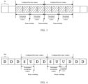
- FIG. 3 is a first schematic diagram of a determined second time window according to an embodiment of this application.
- PUSCH repetition type A repetition type A
- a sequential mapping pattern sequential mapping pattern
- beam switching beam switching
- 2 slots 2 slots.
- UE may divide a first time window into a plurality of second time windows.
- FIG. 4 is a second schematic diagram of a determined second time window according to an embodiment of this application.
- D represents a downlink slot
- S represents a special slot
- U represents an uplink slot.
- PUSCH repetition type A repetition type A
- a sequential mapping pattern sequential mapping pattern
- beam switching beam switching
- TDD time division duplex
- FIG. 5 is a third schematic diagram of a determined second time window according to an embodiment of this application.
- D represents a downlink slot
- S represents a special slot
- U represents an uplink slot.
- a second special slot (special slot) in FIG. 5 is configured with PDCCH monitoring (Configured PDCCH monitoring)
- PDCCH monitoring Configured PDCCH monitoring
- duration duration (duration) without a PDCCH skipping indication or not configured with a PDCCH skipping indication does not include a configured PDCCH monitoring occasion
- UE needs to perform PDCCH monitoring within the special slot.
- the special slot cannot be used for the PUSCH repetition transmission, and a transmission that meets a first condition cannot be maintained either. Therefore, the determined second time window cannot include the special slot.
- FIG. 6 is a fourth schematic diagram of a determined second time window according to an embodiment of this application.
- D represents a downlink slot
- S represents a special slot
- U represents an uplink slot.
- a second special slot (special slot) in FIG. 6 is configured with PDCCH monitoring (Configured PDCCH monitoring)
- PDCCH monitoring Configured PDCCH monitoring
- UE receives a PDCCH skipping indication and duration within which no PDCCH monitoring is performed (No PDCCH monitoring duration) that is indicated by the PDCCH skipping indication includes a configured PDCCH monitoring occasion, the UE does not perform PDCCH monitoring within the special slot. Therefore, the determined second time window can include the special slot.
- FIG. 7 is a fifth schematic diagram of a determined second time window according to an embodiment of this application.
- a maximum gap in which power consistency and phase continuity can be maintained as specified in a frequency band is 8 symbols, or a maximum gap in which current UE can maintain power consistency and phase continuity is 8 symbols, assuming that the UE performs a PUSCH transmission for which DMRS bundling is enabled in the frequency band, where a transmission gap with a length of 6 symbols and a transmission gap with a length of 10 symbols exist, for the transmission gap with the length of 6 symbols, the UE may determine not to divide a first time window, but for the transmission gap with the length of 10 symbols, the UE may determine to divide the first time window to further determine at least one second time window.
- FIG. 8 is a sixth schematic diagram of a determined second time window according to an embodiment of this application.
- the determined second time window is shown in FIG. 8 , where a 1-st hop indicates a first hop of the frequency hopping interval configured by the network, and a 2 nd hop indicates a second hop of the frequency hopping interval configured by the network.
- the terminal can determine the at least one second time window based on the first information and the first time window, where the second time window is the actual DMRS bundling time window, thereby ensuring that even if some configurations or signaling makes an uplink resource unavailable, the uplink transmission can still meet "maintaining power consistency and phase continuity" within the actual DMRS bundling time window. This further facilitates joint channel estimation at a receive end based on the second time window, improves accuracy of channel estimation, and improves a coverage capability.
- time window determination method provided in the embodiments of this application may be performed by a time window determination apparatus or a control module for performing the time window determination method in the time window determination apparatus.
- a time window determination apparatus provided in the embodiments of this application is described by assuming that the time window determination method in the embodiments of this application is performed by the time window determination apparatus.
- FIG. 9 is a schematic diagram of a structure of a time window determination apparatus according to an embodiment of this application. As shown in FIG. 9 , the time window determination apparatus 900 includes a determining module 901.
- the determining module 901 is configured to determine at least one second time window based on first information and a first time window, where the first time window is a configured demodulation reference signal bundling DMRS bundling time window, the second time window is an actual DMRS bundling time window, an uplink transmission within the actual DMRS bundling time window is a transmission that meets a first condition, and the first condition includes maintaining power consistency and phase continuity.
- the apparatus may determine the at least one second time window based on the first information and the first time window, where the second time window is the actual DMRS bundling time window, and the uplink transmission meets "maintaining power consistency and phase continuity" within the actual DMRS bundling time window.
- a terminal can determine the at least one second time window based on the first information and the first time window, where the second time window is the actual DMRS bundling time window, thereby ensuring that even if some configurations or signaling makes an uplink resource unavailable, the uplink transmission can still meet "maintaining power consistency and phase continuity" within the actual DMRS bundling time window. This further facilitates joint channel estimation at a receive end based on the second time window, improves accuracy of channel estimation, and improves a coverage capability.
- the determining module is further configured to:
- the determining module is further configured to:
- the determining module is further configured to:
- the determining module is further configured to:
- the first transmission gap is determined based on at least one of the following:
- the second threshold is determined based on at least one of the following:
- the beam switching configuration information includes cyclic mapping pattern configuration information, where in a case that the beam switching configuration information includes the cyclic mapping pattern configuration information, the cyclic mapping pattern configuration information is not used for beam switching for an uplink transmission configured with joint channel estimation.
- the beam switching configuration information includes sequential mapping pattern configuration information, where in a case that the beam switching configuration information includes the sequential mapping pattern configuration information, if the sequential mapping pattern configuration information is used for beam switching for an uplink transmission configured with joint channel estimation, the number of continuous repetitions or continuous slots that use a same beam in the uplink transmission configured with joint channel estimation is X, where
- X is greater than or equal to N and X is less than or equal to a configured length of the first time window, and N is the number of continuous repetitions or continuous slots that use a same beam as indicated by the sequential mapping pattern configuration information.
- the determining module is further configured to: determine that a moment of frequency hopping position switching indicated by the frequency hopping interval information is an end moment of the second time window.
- the determining module is further configured to: determine that a moment of precoder switching indicated by the precoder cycling granularity configuration information is an end moment of the second time window.
- the apparatus further includes any one of the following:
- the apparatus further includes any one of the following:
- the determining module is further configured to:
- the second transmission gap is determined based on at least one of the following:
- the second event includes at least one of the following:
- the first information is determined in at least one of the following manners:
- the terminal can determine the at least one second time window based on the first information and the first time window, where the second time window is the actual DMRS bundling time window, thereby ensuring that even if some configurations or signaling makes an uplink resource unavailable, the uplink transmission can still meet "maintaining power consistency and phase continuity" within the actual DMRS bundling time window. This further facilitates joint channel estimation at a receive end based on the second time window, improves accuracy of channel estimation, and improves a coverage capability.
- the time window determination apparatus in this embodiment of this application may be an apparatus, or an apparatus or an electronic device with an operating system, or may be a component, an integrated circuit, or a chip in the terminal.
- the apparatus or the electronic device may be a mobile terminal, or may be a nonmobile terminal.
- the mobile terminal may include but is not limited to the foregoing illustrated type of the terminal 11.
- the nonmobile terminal may be a server, a network attached storage (Network Attached Storage, NAS), a personal computer (personal computer, PC), a television (television, TV), a teller machine, a self-service machine, or the like. This is not specifically limited in this embodiment of this application.
- the time window determination apparatus provided in this embodiment of this application can implement each process implemented by the method embodiments in FIG. 2 to FIG. 8 , with the same technical effect achieved. To avoid repetition, details are not described herein again.
- FIG. 10 is a schematic diagram of a structure of a communication device according to an embodiment of this application.
- an embodiment of this application further provides a communication device 1000, including a processor 1001, a memory 1002, and a program or instructions stored in the memory 1002 and executable on the processor 1001.
- a communication device 1000 including a processor 1001, a memory 1002, and a program or instructions stored in the memory 1002 and executable on the processor 1001.
- the communication device 1000 is a terminal, and the program or instructions are executed by the processor 1001, each process of the foregoing embodiment of the time window determination method is implemented, with the same technical effect achieved.
- An embodiment of this application further provides a terminal, including a processor and a communication interface.
- the processor is configured to:
- FIG. 11 is a schematic diagram of a hardware structure of a terminal for implementing an embodiment of this application.
- the terminal 1100 includes but is not limited to at least some components such as a radio frequency unit 1101, a network module 1102, an audio output unit 1103, an input unit 1104, a sensor 1105, a display unit 1106, a user input unit 1107, an interface unit 1108, a memory 1109, and a processor 1110.
- the terminal 1100 may further include a power supply (for example, a battery) supplying power to all components.
- the power supply may be logically connected to the processor 1110 through a power management system. In this way, functions such as charge management, discharge management, and power consumption management are implemented by using the power management system.
- the terminal structure shown in FIG. 11 does not constitute a limitation on the terminal.
- the terminal may include more or fewer components than those shown in the figure, or some components are combined, or component arrangements are different. Details are not described herein again.
- the input unit 1104 may include a graphics processing unit (Graphics Processing Unit, GPU) 11041 and a microphone 11042.
- the graphics processing unit 11041 processes image data of a still picture or video obtained by an image capture apparatus (such as a camera) in a video capture mode or an image capture mode.
- the display unit 1106 may include a display panel 11061, and the display panel 11061 may be configured in a form of a liquid crystal display, an organic light-emitting diode, or the like.
- the user input unit 1107 includes a touch panel 11071 and other input devices 11072.
- the touch panel 11071 is also referred to as a touchscreen.
- the touch panel 11071 may include two parts: a touch detection apparatus and a touch controller.
- the other input devices 11072 may include but are not limited to a physical keyboard, a function button (such as a volume control button or a power button), a trackball, a mouse, and a joystick. Details are not described herein again.
- the radio frequency unit 1101 after receiving downlink data from a network-side device, the radio frequency unit 1101 sends the downlink data to the processor 1110 for processing, and in addition, sends uplink data to the network-side device.
- the radio frequency unit 1101 includes but is not limited to an antenna, at least one amplifier, a transceiver, a coupler, a low noise amplifier, a duplexer, and the like.
- the memory 1109 may be configured to store software programs or instructions and various data.
- the memory 1109 may primarily include a program or instruction storage area and a data storage area.
- the program or instruction storage area may store an operating system, an application program or instructions (such as an audio play function and an image play function) required by at least one function, and the like.
- the memory 1109 may include a high-speed random access memory, and may further include a non-volatile memory.
- the non-volatile memory may be a read-only memory (Read-Only Memory, ROM), a programmable read-only memory (Programmable ROM, PROM), an erasable programmable read-only memory (Erasable PROM, EPROM), an electrically erasable programmable read-only memory (Electrically EPROM, EEPROM), or a flash memory, for example, at least one disk storage device, a flash memory device, or another non-volatile solid-state storage device.
- ROM Read-Only Memory
- PROM programmable read-only memory
- Erasable PROM Erasable PROM
- EPROM electrically erasable programmable read-only memory
- EEPROM electrically erasable programmable read-only memory
- flash memory for example, at least one disk storage device, a flash memory device, or another non-volatile solid-state storage device.
- the processor 1110 may include one or more processing units.
- the processor 1110 may integrate an application processor and a modem processor.
- the application processor mainly processes the operating system, a user interface, an application program or an instruction, and the like.
- the modem processor mainly processes wireless communication.
- the modem processor is a baseband processor. It may be understood that the modem processor may alternatively not be integrated in the processor 1110.
- the processor 1110 is configured to:
- the terminal can determine the at least one second time window based on the first information and the first time window, where the second time window is the actual DMRS bundling time window, thereby ensuring that even if some configurations or signaling makes an uplink resource unavailable, the uplink transmission can still meet "maintaining power consistency and phase continuity" within the actual DMRS bundling time window. This further facilitates joint channel estimation at a receive end based on the second time window, improves accuracy of channel estimation, and improves a coverage capability.
- processor 1110 is further configured to perform at least one of the following:
- processor 1110 is further configured to:
- processor 1110 is further configured to:
- processor 1110 is further configured to:
- the first transmission gap is determined based on at least one of the following:
- the second threshold is determined based on at least one of the following:
- the beam switching configuration information includes cyclic mapping pattern configuration information, where in a case that the beam switching configuration information includes the cyclic mapping pattern configuration information, the cyclic mapping pattern configuration information is not used for beam switching for an uplink transmission configured with joint channel estimation.
- the beam switching configuration information includes sequential mapping pattern configuration information, where
- the processor 1110 is further configured to: determine that a moment of frequency hopping position switching indicated by the frequency hopping interval information is an end moment of the second time window.
- the processor 1110 is further configured to: determine that a moment of precoder switching indicated by the precoder cycling granularity configuration information is an end moment of the second time window.
- the processor 1110 is further configured to perform any one of the following:
- the processor 1110 is further configured to perform any one of the following:
- processor 1110 is further configured to:
- the second transmission gap is determined based on at least one of the following:
- the second event includes at least one of the following:
- the first information is determined in at least one of the following manners:
- the terminal can determine the at least one second time window based on the first information and the first time window, where the second time window is the actual DMRS bundling time window, thereby ensuring that even if some configurations or signaling makes an uplink resource unavailable, the uplink transmission can still meet "maintaining power consistency and phase continuity" within the actual DMRS bundling time window. This further facilitates joint channel estimation at a receive end based on the second time window, improves accuracy of channel estimation, and improves a coverage capability.
- An embodiment of this application further provides a readable storage medium.
- the readable storage medium stores a program or instructions.
- the program or instructions are executed by a processor, each process of the foregoing embodiment of the time window determination method is implemented, with the same technical effect achieved. To avoid repetition, details are not described herein again.
- the processor is a processor in the terminal in the foregoing embodiment.
- the readable storage medium includes a readable storage medium, for example, a computer read-only memory (Read-Only Memory, ROM), a random access memory (Random Access Memory, RAM), a magnetic disk, or an optical disc.
- an embodiment of this application provides a chip, where the chip includes a processor and a communication interface, the communication interface is coupled to the processor, and the processor is configured to run a program or instructions to implement each process of the foregoing embodiment of the time window determination method, with the same technical effect achieved. To avoid repetition, details are not described herein again.
- the chip provided in this embodiment of this application may also be referred to as a system-level chip, a system chip, a chip system, a system-on-chip, or the like.
- An embodiment of this application further provides a computer program or program product.
- the computer program or program product is stored in a non-transitory storage medium.
- the program or program product is executed by at least one processor to implement each process of the foregoing embodiment of the time window determination method, with the same technical effect achieved. To avoid repetition, details are not described herein again.
- the methods in the foregoing embodiments may be implemented by using software in combination with a necessary general hardware platform, and certainly may alternatively be implemented by using hardware. However, in most cases, the former is a preferred implementation.
- the technical solutions of this application essentially or the part contributing to the prior art may be implemented in a form of a computer software product.
- the computer software product is stored in a storage medium (such as a ROM/RAM, a magnetic disk, or an optical disc), and includes several instructions for instructing a terminal (which may be a mobile phone, a computer, a server, a network device, or the like) to perform the methods described in the embodiments of this application.
Landscapes
- Engineering & Computer Science (AREA)
- Signal Processing (AREA)
- Computer Networks & Wireless Communication (AREA)
- Power Engineering (AREA)
- Mobile Radio Communication Systems (AREA)
Applications Claiming Priority (2)
| Application Number | Priority Date | Filing Date | Title |
|---|---|---|---|
| CN202111153057.1A CN115883041B (zh) | 2021-09-29 | 2021-09-29 | 时间窗的确定方法、装置、终端及存储介质 |
| PCT/CN2022/121272 WO2023051450A1 (zh) | 2021-09-29 | 2022-09-26 | 时间窗的确定方法、装置、终端及存储介质 |
Publications (2)
| Publication Number | Publication Date |
|---|---|
| EP4412353A1 true EP4412353A1 (de) | 2024-08-07 |
| EP4412353A4 EP4412353A4 (de) | 2025-02-12 |
Family
ID=85756232
Family Applications (1)
| Application Number | Title | Priority Date | Filing Date |
|---|---|---|---|
| EP22874836.4A Pending EP4412353A4 (de) | 2021-09-29 | 2022-09-26 | Verfahren und vorrichtung zur bestimmung eines zeitfensters sowie endgerät und speichermedium |
Country Status (6)
| Country | Link |
|---|---|
| US (1) | US20240235779A1 (de) |
| EP (1) | EP4412353A4 (de) |
| JP (1) | JP2024535910A (de) |
| KR (1) | KR20240071412A (de) |
| CN (1) | CN115883041B (de) |
| WO (1) | WO2023051450A1 (de) |
Families Citing this family (7)
| Publication number | Priority date | Publication date | Assignee | Title |
|---|---|---|---|---|
| CN115707359B (zh) * | 2021-05-20 | 2026-01-02 | 北京小米移动软件有限公司 | 参数配置方法及装置、电子设备及存储介质 |
| US20240031963A1 (en) * | 2022-07-20 | 2024-01-25 | Qualcomm Incorporated | Priority-based timing advance (ta) adjustment |
| EP4657934A1 (de) * | 2023-04-07 | 2025-12-03 | Hyundai Motor Company | Verfahren und vorrichtung zur timing-anpassung in einem nicht terrestrischen netzwerk |
| EP4665018A1 (de) * | 2023-05-12 | 2025-12-17 | Hyundai Motor Company | Verfahren und vorrichtung zur timing-anpassung in einem nicht terrestrischen netzwerk |
| CN119450713A (zh) * | 2023-07-31 | 2025-02-14 | 维沃移动通信有限公司 | 传输控制方法、传输调度方法、传输配置方法及相关设备 |
| WO2025030543A1 (en) * | 2023-08-10 | 2025-02-13 | Nec Corporation | Devices and methods for communication |
| CN119485137A (zh) * | 2023-08-10 | 2025-02-18 | 华为技术有限公司 | 一种通信方法及装置 |
Family Cites Families (12)
| Publication number | Priority date | Publication date | Assignee | Title |
|---|---|---|---|---|
| US8976878B2 (en) * | 2013-01-15 | 2015-03-10 | Raytheon Company | Polynomial phases for multi-carrier modulation schemes with time domain windowing |
| CN116321495A (zh) * | 2017-12-22 | 2023-06-23 | 上海朗帛通信技术有限公司 | 一种被用于无线通信的用户设备、基站中的方法和装置 |
| US11101950B2 (en) * | 2018-01-12 | 2021-08-24 | Qualcomm Incorporated | Demodulation reference signal (DMRS) bundling in slot aggregation and slot format considerations for new radio |
| WO2020111839A1 (ko) * | 2018-11-28 | 2020-06-04 | 엘지전자 주식회사 | 무선 통신 시스템에서 무선 신호 송수신 방법 및 장치 |
| CN111756509B (zh) * | 2019-03-29 | 2022-04-29 | 华为技术有限公司 | 一种传输公共信号块的方法和装置 |
| US11310088B2 (en) * | 2019-07-11 | 2022-04-19 | Qualcomm Incorporated | Physical shared channel reference signal bundling |
| CN110766051A (zh) * | 2019-09-20 | 2020-02-07 | 四川大学华西医院 | 一种基于神经网络的肺结节形态学分类方法 |
| CN112702779B (zh) * | 2019-10-23 | 2023-01-06 | 维沃移动通信有限公司 | 一种上行传输功率分配方法及终端 |
| WO2021159362A1 (en) * | 2020-02-13 | 2021-08-19 | Qualcomm Incorporated | Demodulation reference signal time domain bundling |
| KR20250084247A (ko) * | 2021-04-01 | 2025-06-10 | 베이징 시아오미 모바일 소프트웨어 컴퍼니 리미티드 | 지시 방법, 지시 장치 및 저장 매체 |
| US12225458B2 (en) * | 2021-09-20 | 2025-02-11 | Samsung Electronics Co., Ltd. | Method and apparatus for same power transmissions |
| CN117957807A (zh) * | 2021-09-28 | 2024-04-30 | Lg电子株式会社 | 在无线通信系统中基于解调参考信号集束发送或接收上行链路信道的方法和装置 |
-
2021
- 2021-09-29 CN CN202111153057.1A patent/CN115883041B/zh active Active
-
2022
- 2022-09-26 JP JP2024518692A patent/JP2024535910A/ja active Pending
- 2022-09-26 EP EP22874836.4A patent/EP4412353A4/de active Pending
- 2022-09-26 WO PCT/CN2022/121272 patent/WO2023051450A1/zh not_active Ceased
- 2022-09-26 KR KR1020247014316A patent/KR20240071412A/ko active Pending
-
2024
- 2024-03-27 US US18/617,847 patent/US20240235779A1/en active Pending
Also Published As
| Publication number | Publication date |
|---|---|
| US20240235779A1 (en) | 2024-07-11 |
| CN115883041B (zh) | 2024-08-23 |
| JP2024535910A (ja) | 2024-10-02 |
| CN115883041A (zh) | 2023-03-31 |
| WO2023051450A1 (zh) | 2023-04-06 |
| KR20240071412A (ko) | 2024-05-22 |
| EP4412353A4 (de) | 2025-02-12 |
Similar Documents
| Publication | Publication Date | Title |
|---|---|---|
| EP4412353A1 (de) | Verfahren und vorrichtung zur bestimmung eines zeitfensters sowie endgerät und speichermedium | |
| EP4398663A1 (de) | Überwachungsverfahren und -vorrichtung, wecksignalübertragungsverfahren und -vorrichtung, endgerät und netzwerkseitige vorrichtung | |
| EP4510701A1 (de) | Zellumschaltungsverfahren, zellumschaltungskonfigurationsverfahren und -vorrichtung, endgerät und netzwerkseitige vorrichtung | |
| CN115529113B (zh) | 参考信号的传输方法和设备 | |
| JP7760046B2 (ja) | 伝送処理方法、装置、端末、ネットワーク側機器及び記憶媒体 | |
| EP4366365A1 (de) | Positionierungsmessverfahren und positionierungskonfigurationsverfahren und -vorrichtungen sowie kommunikationsvorrichtung | |
| US20240188166A1 (en) | Data Transmission Method for Small Data Transmission (SDT) and Terminal | |
| EP4525535A1 (de) | Signalverarbeitungsverfahren, endgerät und netzwerkvorrichtung | |
| US20240080818A1 (en) | Method and apparatus for determining uplink transmission time window, terminal, and network-side device | |
| EP4373174A1 (de) | Verfahren und vorrichtung zur bestimmung des tci-status sowie endgerät und netzwerkseitige vorrichtung | |
| CN115696539B (zh) | 发送功率的确定方法、装置、终端及存储介质 | |
| EP4451767A1 (de) | Referenzbestimmungsverfahren und -vorrichtung sowie kommunikationsvorrichtung und lesbares speichermedium | |
| US20230421293A1 (en) | Transmission processing method and apparatus and terminal | |
| US20240284457A1 (en) | Information processing method and apparatus, communication device, and readable storage medium | |
| US12593373B2 (en) | Discontinuous reception configuration method and device | |
| EP4224766A1 (de) | Klangreferenzsignalkonfigurationsverfahren, endgerät und netzwerkseitige vorrichtung | |
| EP4398630A1 (de) | Übertragungsverarbeitungsverfahren und -vorrichtung, endgerät und speichermedium | |
| EP4307820A1 (de) | Cot-bestimmungsverfahren, uplink-übertragungsverfahren und -vorrichtung | |
| EP4274143A1 (de) | Signalkonfigurationsverfahren und -vorrichtung, vorrichtung und speichermedium | |
| CN117295123A (zh) | 切换处理方法、装置及通信设备 | |
| US12621104B2 (en) | Sounding reference signal configuration method, terminal and network-side device | |
| CN115811792B (zh) | 传输方法和设备 | |
| EP4447363A1 (de) | Verfahren und vorrichtung zur bestimmung eines zeitfensters, endgerät und lesbares speichermedium | |
| EP4468784A1 (de) | Verfahren zur bestimmung einer wellenform auf bwp und endgerät | |
| EP4404620A1 (de) | Ressourcenreservierungsverfahren und -vorrichtung sowie endgerät |
Legal Events
| Date | Code | Title | Description |
|---|---|---|---|
| STAA | Information on the status of an ep patent application or granted ep patent |
Free format text: STATUS: THE INTERNATIONAL PUBLICATION HAS BEEN MADE |
|
| PUAI | Public reference made under article 153(3) epc to a published international application that has entered the european phase |
Free format text: ORIGINAL CODE: 0009012 |
|
| STAA | Information on the status of an ep patent application or granted ep patent |
Free format text: STATUS: REQUEST FOR EXAMINATION WAS MADE |
|
| 17P | Request for examination filed |
Effective date: 20240429 |
|
| AK | Designated contracting states |
Kind code of ref document: A1 Designated state(s): AL AT BE BG CH CY CZ DE DK EE ES FI FR GB GR HR HU IE IS IT LI LT LU LV MC MK MT NL NO PL PT RO RS SE SI SK SM TR |
|
| DAV | Request for validation of the european patent (deleted) | ||
| DAX | Request for extension of the european patent (deleted) | ||
| A4 | Supplementary search report drawn up and despatched |
Effective date: 20250114 |
|
| RIC1 | Information provided on ipc code assigned before grant |
Ipc: H04W 52/38 20090101ALN20250108BHEP Ipc: H04W 52/14 20090101ALN20250108BHEP Ipc: H04L 5/00 20060101ALI20250108BHEP Ipc: H04W 72/04 20230101AFI20250108BHEP |