EP4414105A1 - Débits d'alimentation de caractéristiques d'apprentissage automatique pour impression 3d - Google Patents
Débits d'alimentation de caractéristiques d'apprentissage automatique pour impression 3d Download PDFInfo
- Publication number
- EP4414105A1 EP4414105A1 EP24153007.0A EP24153007A EP4414105A1 EP 4414105 A1 EP4414105 A1 EP 4414105A1 EP 24153007 A EP24153007 A EP 24153007A EP 4414105 A1 EP4414105 A1 EP 4414105A1
- Authority
- EP
- European Patent Office
- Prior art keywords
- toolpath
- feed rate
- data
- training
- machine learning
- Prior art date
- Legal status (The legal status is an assumption and is not a legal conclusion. Google has not performed a legal analysis and makes no representation as to the accuracy of the status listed.)
- Pending
Links
Images



Classifications
-
- G—PHYSICS
- G05—CONTROLLING; REGULATING
- G05B—CONTROL OR REGULATING SYSTEMS IN GENERAL; FUNCTIONAL ELEMENTS OF SUCH SYSTEMS; MONITORING OR TESTING ARRANGEMENTS FOR SUCH SYSTEMS OR ELEMENTS
- G05B19/00—Program-control systems
- G05B19/02—Program-control systems electric
- G05B19/18—Numerical control [NC], i.e. automatically operating machines, in particular machine tools, e.g. in a manufacturing environment, so as to execute positioning, movement or co-ordinated operations by means of program data in numerical form
- G05B19/4097—Numerical control [NC], i.e. automatically operating machines, in particular machine tools, e.g. in a manufacturing environment, so as to execute positioning, movement or co-ordinated operations by means of program data in numerical form characterised by using design data to control NC machines, e.g. CAD/CAM
- G05B19/4099—Surface or curve machining, making three-dimensional [3D] objects, e.g. desktop manufacturing
-
- B—PERFORMING OPERATIONS; TRANSPORTING
- B22—CASTING; POWDER METALLURGY
- B22F—WORKING METALLIC POWDER; MANUFACTURE OF ARTICLES FROM METALLIC POWDER; MAKING METALLIC POWDER; APPARATUS OR DEVICES SPECIALLY ADAPTED FOR METALLIC POWDER
- B22F10/00—Additive manufacturing of workpieces or articles from metallic powder
- B22F10/30—Process control
- B22F10/38—Process control to achieve specific product aspects, e.g. surface smoothness, density, porosity or hollow structures
- B22F10/385—Overhang structures
-
- B—PERFORMING OPERATIONS; TRANSPORTING
- B22—CASTING; POWDER METALLURGY
- B22F—WORKING METALLIC POWDER; MANUFACTURE OF ARTICLES FROM METALLIC POWDER; MAKING METALLIC POWDER; APPARATUS OR DEVICES SPECIALLY ADAPTED FOR METALLIC POWDER
- B22F10/00—Additive manufacturing of workpieces or articles from metallic powder
- B22F10/20—Direct sintering or melting
- B22F10/22—Direct deposition of molten metal
-
- B—PERFORMING OPERATIONS; TRANSPORTING
- B22—CASTING; POWDER METALLURGY
- B22F—WORKING METALLIC POWDER; MANUFACTURE OF ARTICLES FROM METALLIC POWDER; MAKING METALLIC POWDER; APPARATUS OR DEVICES SPECIALLY ADAPTED FOR METALLIC POWDER
- B22F10/00—Additive manufacturing of workpieces or articles from metallic powder
- B22F10/80—Data acquisition or data processing
-
- B—PERFORMING OPERATIONS; TRANSPORTING
- B22—CASTING; POWDER METALLURGY
- B22F—WORKING METALLIC POWDER; MANUFACTURE OF ARTICLES FROM METALLIC POWDER; MAKING METALLIC POWDER; APPARATUS OR DEVICES SPECIALLY ADAPTED FOR METALLIC POWDER
- B22F10/00—Additive manufacturing of workpieces or articles from metallic powder
- B22F10/80—Data acquisition or data processing
- B22F10/85—Data acquisition or data processing for controlling or regulating additive manufacturing processes
-
- B—PERFORMING OPERATIONS; TRANSPORTING
- B29—WORKING OF PLASTICS; WORKING OF SUBSTANCES IN A PLASTIC STATE IN GENERAL
- B29C—SHAPING OR JOINING OF PLASTICS; SHAPING OF MATERIAL IN A PLASTIC STATE, NOT OTHERWISE PROVIDED FOR; AFTER-TREATMENT OF THE SHAPED PRODUCTS, e.g. REPAIRING
- B29C64/00—Additive manufacturing, i.e. manufacturing of three-dimensional [3D] objects by additive deposition, additive agglomeration or additive layering, e.g. by 3D printing, stereolithography or selective laser sintering
- B29C64/30—Auxiliary operations or equipment
- B29C64/386—Data acquisition or data processing for additive manufacturing
-
- B—PERFORMING OPERATIONS; TRANSPORTING
- B29—WORKING OF PLASTICS; WORKING OF SUBSTANCES IN A PLASTIC STATE IN GENERAL
- B29C—SHAPING OR JOINING OF PLASTICS; SHAPING OF MATERIAL IN A PLASTIC STATE, NOT OTHERWISE PROVIDED FOR; AFTER-TREATMENT OF THE SHAPED PRODUCTS, e.g. REPAIRING
- B29C64/00—Additive manufacturing, i.e. manufacturing of three-dimensional [3D] objects by additive deposition, additive agglomeration or additive layering, e.g. by 3D printing, stereolithography or selective laser sintering
- B29C64/30—Auxiliary operations or equipment
- B29C64/386—Data acquisition or data processing for additive manufacturing
- B29C64/393—Data acquisition or data processing for additive manufacturing for controlling or regulating additive manufacturing processes
-
- B—PERFORMING OPERATIONS; TRANSPORTING
- B33—ADDITIVE MANUFACTURING TECHNOLOGY
- B33Y—ADDITIVE MANUFACTURING, i.e. MANUFACTURING OF THREE-DIMENSIONAL [3D] OBJECTS BY ADDITIVE DEPOSITION, ADDITIVE AGGLOMERATION OR ADDITIVE LAYERING, e.g. BY 3D PRINTING, STEREOLITHOGRAPHY OR SELECTIVE LASER SINTERING
- B33Y10/00—Processes of additive manufacturing
-
- B—PERFORMING OPERATIONS; TRANSPORTING
- B33—ADDITIVE MANUFACTURING TECHNOLOGY
- B33Y—ADDITIVE MANUFACTURING, i.e. MANUFACTURING OF THREE-DIMENSIONAL [3D] OBJECTS BY ADDITIVE DEPOSITION, ADDITIVE AGGLOMERATION OR ADDITIVE LAYERING, e.g. BY 3D PRINTING, STEREOLITHOGRAPHY OR SELECTIVE LASER SINTERING
- B33Y50/00—Data acquisition or data processing for additive manufacturing
- B33Y50/02—Data acquisition or data processing for additive manufacturing for controlling or regulating additive manufacturing processes
-
- G—PHYSICS
- G06—COMPUTING OR CALCULATING; COUNTING
- G06N—COMPUTING ARRANGEMENTS BASED ON SPECIFIC COMPUTATIONAL MODELS
- G06N20/00—Machine learning
-
- G—PHYSICS
- G06—COMPUTING OR CALCULATING; COUNTING
- G06N—COMPUTING ARRANGEMENTS BASED ON SPECIFIC COMPUTATIONAL MODELS
- G06N20/00—Machine learning
- G06N20/10—Machine learning using kernel methods, e.g. support vector machines [SVM]
-
- G—PHYSICS
- G06—COMPUTING OR CALCULATING; COUNTING
- G06N—COMPUTING ARRANGEMENTS BASED ON SPECIFIC COMPUTATIONAL MODELS
- G06N3/00—Computing arrangements based on biological models
- G06N3/02—Neural networks
- G06N3/08—Learning methods
- G06N3/09—Supervised learning
-
- G—PHYSICS
- G05—CONTROLLING; REGULATING
- G05B—CONTROL OR REGULATING SYSTEMS IN GENERAL; FUNCTIONAL ELEMENTS OF SUCH SYSTEMS; MONITORING OR TESTING ARRANGEMENTS FOR SUCH SYSTEMS OR ELEMENTS
- G05B2219/00—Program-control systems
- G05B2219/30—Nc systems
- G05B2219/33—Director till display
- G05B2219/33002—Artificial intelligence AI, expert, knowledge, rule based system KBS
-
- G—PHYSICS
- G05—CONTROLLING; REGULATING
- G05B—CONTROL OR REGULATING SYSTEMS IN GENERAL; FUNCTIONAL ELEMENTS OF SUCH SYSTEMS; MONITORING OR TESTING ARRANGEMENTS FOR SUCH SYSTEMS OR ELEMENTS
- G05B2219/00—Program-control systems
- G05B2219/30—Nc systems
- G05B2219/49—Nc machine tool, till multiple
- G05B2219/49023—3-D printing, layer of powder, add drops of binder in layer, new powder
-
- G—PHYSICS
- G06—COMPUTING OR CALCULATING; COUNTING
- G06F—ELECTRIC DIGITAL DATA PROCESSING
- G06F2113/00—Details relating to the application field
- G06F2113/10—Additive manufacturing, e.g. three-dimensional [3D] printing
-
- G—PHYSICS
- G06—COMPUTING OR CALCULATING; COUNTING
- G06F—ELECTRIC DIGITAL DATA PROCESSING
- G06F30/00—Computer-aided design [CAD]
- G06F30/20—Design optimisation, verification or simulation
- G06F30/27—Design optimisation, verification or simulation using machine learning, e.g. artificial intelligence, neural networks, support vector machines [SVM] or training a model
Definitions
- This disclosure relates generally to three-dimensional (3D) printing.
- 3D printing an object can proceed in layers according to a Cartesian coordinate system oriented such that each layer is parallel to the XY plane, e.g., representing the horizontal surface of the Earth, with additional layers added to extend the object in the Z-axis direction, e.g., representing up and down relative to gravity.
- Deposition of print material for each layer may be provided according to a toolpath, that is, a defined route of the deposition nozzle.
- the toolpath may be specified by computer readable toolpath instructions, such as a GCode file. Additional layers may be added to build the object in the Z axis direction.
- 3D printing may be used to manufacture complex 3D designs that otherwise could not be made using traditional methods such as machining, casting, or injection molding. This ability is made possible through the aforementioned layered printing process.
- complex features such as re-entrant geometries, hollow features, fine features which the traditional tools cannot machine owing to space constraints or reachability, and the like, are divided among multiple layers and fairly simple 2D layers are printed one above the other until the entire object is completed in this fashion.
- each 3D printing process by virtue of its working principle or construction has its own challenges to address.
- One such common challenge manifests in the form of overhangs.
- An overhang is a feature of a 3D printed part that is unsupported by an underlying support structure.
- a layer-by-layer printing approach can produce one or more undersides of a slope in a part, where each subsequent layer must protrude slightly beyond a preceding layer.
- gravity and other factors such as the angle and slope of the overhang, can result in drooping or sagging, curling, or the prohibition of printing a desired shape altogether.
- the feed rate that is the rate of print material flow through the print nozzle (e.g., extrusion rate, flow rate, drop rate, etc.) of print material to produce a specified layer thickness
- the feed rate that is the rate of print material flow through the print nozzle (e.g., extrusion rate, flow rate, drop rate, etc.) of print material to produce a specified layer thickness
- this does not generally hold for features of anisotropic regions, which can include outer perimeters, thin features, and overhangs. This is because the 3D printer system's response at such edge-type regions are functions of flow, temperature, and other variables.
- the most direct method of calculating the appropriate feed rates is to print the feature type at several different feed rates and have a metric or visual assessment that measures the part quality. This can be laborious and time consuming for multiple part types.
- a method of providing a feed rate for three-dimensional printing a part includes: obtaining computer readable toolpath instructions for the part, where the toolpath instructions specify a nominal feed rate for a toolpath segment and spatial toolpath data of the toolpath segment; providing an input including the spatial toolpath data to a trained machine learning system, where the trained machine learning system has been trained using training data including: training spatial toolpath data, training closed loop gain data, and training feed rate data; obtaining a revised feed rate for the toolpath segment different from the nominal feed rate for the toolpath segment, where the revised feed rate is output from the trained machine learning system; and providing revised computer readable toolpath instructions, where the revised machine learning toolpath instructions include the revised feed rate.
- the method may include printing the part using the revised computer readable toolpath instructions.
- the input may further include a predetermined closed loop gain value.
- the training data may include data that is specific to the part, and the method may further include training the trained machine learning system using the training data.
- the toolpath instructions may specify an anisotropic region of the part that includes the toolpath segment.
- the anisotropic region may include at least one of: an overhang, an outer perimeter, or a thin feature.
- the spatial toolpath data for the toolpath segment may include at least one of: a distance from an edge of the part, a distance from a corner of the part, or a rounding radius of the toolpath segment.
- the training data may further include training overhang angle data.
- the training feed rate data may include an induced feed rate variation.
- the induced feed rate variation may include a periodic induced feed rate variation along an edge of a feature.
- a system for providing a feed rate for three-dimensional printing a part includes an electronic processor and a persistent memory storing non-transitory computer readable instructions that, when executed by the electronic processor, configure the electronic processor to perform actions including: obtaining computer readable toolpath instructions for the part, where the toolpath instructions specify a nominal feed rate for a toolpath segment and spatial toolpath data of the toolpath segment; providing an input including the spatial toolpath data to a trained machine learning system, where the trained machine learning system has been trained using training data including: training spatial toolpath data, training closed loop gain data, and training feed rate data; obtaining a revised feed rate for the toolpath segment different from the nominal feed rate for the toolpath segment, where the revised feed rate is output from the trained machine learning system; and providing revised computer readable toolpath instructions, where the revised machine learning toolpath instructions include the revised feed rate.
- the actions may further include printing the part using the revised computer readable toolpath instructions.
- the input may further include a predetermined closed loop gain value.
- the training data may include data that is specific to the part, and the actions may further include training the trained machine learning system using the training data.
- the toolpath instructions may specify an anisotropic region of the part that includes the toolpath segment.
- the anisotropic region may include at least one of: an overhang, an outer perimeter, or a thin feature.
- the spatial toolpath data for the toolpath segment may include at least one of: a distance from an edge of the part, a distance from a corner of the part, or a rounding radius of the toolpath segment.
- the training data may further include training overhang angle data.
- the training feed rate data may include an induced feed rate variation.
- the induced feed rate variation may include a periodic induced feed rate variation along an edge of a feature.
- Various embodiments use the closed loop of some 3D printing processes to determine an appropriate feed rate to use with a given feature type.
- machine learning is employed within a closed loop system context.
- a given feature is printed using multiple induced feed rates along the edge of the feature, with the response of the closed loop Z-axis height correction system being captured.
- the distances to the edge and/or corner of the feature, along with the closed loop response are used to train a neural network that predicts the open loop feed rate used.
- the appropriate feed rate is then chosen as the one that corresponds to the closed loop system not modifying the open loop response.
- some embodiments automatically determine an appropriate feed rate for special features in 3D printing, without having to print multiple instances of the features and without having to apply visual inspection or an external network.
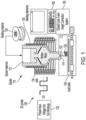
- Fig. 1 depicts a schematic cross-sectional side view of a 3D printer 100, according to various embodiments.
- the 3D printer 100 may be or include a magnetohydrodynamic (MHD) printer, a piezoelectric-driven printer, or the like.
- the 3D printer 100 may include an ejector (also referred to as a pump) 110.
- the ejector 110 refers to a structure that can be selectively activated to cause a build material 120 to be ejected from a nozzle 114 of the ejector 110.
- the ejector 110 may define one or more reservoirs 112.
- One ejector reservoir 112 is shown in Fig. 1 .
- the ejector 110 may include two or more reservoirs including at least a first (e.g., upper) reservoir and a second (e.g., lower) reservoir.
- the portion of the ejector 110 defining the upper reservoir may be or include a ceramic material
- the portion of the ejector 110 defining the lower reservoir may be or include a graphite material.
- the ejector reservoir (s) 112 is/are configured to receive and/or store the build material 120 that is to be ejected from the nozzle 114.
- the build material 120 may be or include a metal, a polymer, a ceramic, or the like. In one embodiment, the build material 120 may be greater than about 50% metal, greater than 60% metal, greater than 70% metal, greater than 80% metal, greater than 90% metal, or about 100% metal (e.g., by volume or mass).
- the build material 120 may be or include a spool of aluminum wire (e.g., 6061 aluminum). In another embodiment, the build material 120 may be or include copper or other metals.
- the 3D printer 100 may also include one or more heating elements 130.
- the heating elements 130 may be configured to melt the build material 120 within the ejector reservoir 112, thereby converting the build material 120 from a solid state to a liquid (e.g., molten) state within the ejector reservoir 112.
- the 3D printer 100 may also include a power source 132 and one or more metallic coils 134.
- the metallic coils 134 are wrapped at least partially around the ejector 110 and/or the heating elements 130.
- the power source 132 may be coupled to the coils 134 and configured to provide power thereto.
- the power source 132 may be configured to provide a step function direct current (DC) voltage profile (e.g., voltage pulses or jetting pulses) to the coils 134, which may create an increasing magnetic field.
- the increasing magnetic field may cause an electromotive force within the ejector 110, that in turn causes an induced electrical current in the liquid build material 120.
- DC direct current
- the magnetic field and the induced electrical current in the liquid build material 120 may create a radially inward force on the liquid build material 120, known as a Lorentz force.
- the Lorentz force creates a pressure at an inlet of the nozzle 114 of the ejector 110.
- the pressure causes the liquid build material 120 to be jetted through and/or ejected from the nozzle 114 in the form of one or more drops 122.
- the 3D printer 100 may include a build plate (also referred to as a substrate) 140 that is positioned below the nozzle 114.
- the drops 122 may be ejected from the nozzle 114 and subsequently land on the build plate 140 where they may cool and solidify to form a first (e.g., bottom) layer. Additional drops 122 may be jetted to form layer upon layer that eventually produces a 3D part 124.
- the 3D printer 100 may also include one or more substrate control motors that are configured to move the build plate 140 while the drops 122 are being ejected through the nozzle 114, or during pauses between when the drops 122 are being ejected through the nozzle 114, to cause the 3D part to have the desired shape and size.
- the substrate control motors may be configured to move the substrate in one dimension (e.g., along the X -axis), in two dimensions (e.g., along the X -axis and the Y -axis), or in three dimensions (e.g., along the X -axis, the Y -axis, and the Z -axis).
- the nozzle 114 may be also or instead be configured to move in one, two, or three dimensions.
- the build plate 140 may be moved under a stationary nozzle 114, or the nozzle 114 may be moved above a stationary build plate 140.
- both the nozzle 114 and the build plate 140 may move.
- the build plate 140 may move in X and Y directions, while the nozzle 114 may move up and/or down in the Z direction.
- the 3D printer 100 may include a closed loop Z-axis height correction system 150, which monitors the height of the deposition and corrects the feed rate accordingly.
- the closed loop Z-axis height correction system 150 may include a camera or a (e.g., laser) scanner that is configured to capture a feed (e.g., video and/or images) of the nozzle 114, the drops 122, the 3D part 124, or a combination thereof.
- the camera captures images of the part as the drops are deposited, which may be analyzed to determine whether the deposition height at a given layer is within specification.
- the camera may be configured to capture the feed of the drops 122 as they are falling. More particularly, the feed may show the drops 122 after they are ejected from the nozzle 122 and before they land on the build plate 140. The size, shape, mass, and/or direction of the drops 122 may be determined based upon the feed.
- While the closed loop Z-axis height correction system 150 can correct the feed rate based on the monitored deposition height as a part is being printed, such correction leaves an error in the printed part. Multiple such errors can occur and accumulate, and the resulting part can be out of spec and unusable.
- the 3D printer 100 may also include a computing system 160.
- the computing system 160 may perform at least a portion of the methods described herein in reference to Figs. 6 and 7 , for example.
- Fig. 2 depicts a part overhang feature 200 according to various embodiments.
- each subsequent layer of the overhang feature 100 will slightly project beyond the previous layer.
- Such projections along with variations in temperature, for example, can generate print errors if a nominal feed rate typically used for an interior deposition is used for the edge of the feature.
- a closed loop Z -axis height correction system can correct the feed rate, each correction may nevertheless leave an undesirable artifact. Such artifacts may disadvantageously accrue, and result in an undesirable part.
- the feed rate may be varied along the edge of the feature, such as along the edge of a layer of the overhang feature 200, as a function of position (e.g., rather than the feed rate being set according to a nominal feed rate and adjusted in real time during printing by the closed loop Z -height correction system).
- a feed rate variation at every point can be induced as shown and described in reference to Fig. 3 , for example. Both the feed rate variations and the responses of the closed loop system can be recorded and used to train a machine learning system, according to various embodiments as described in detail herein.
- Fig. 3 depicts an induced feed rate variation map 300 according to various embodiments. For example, if the value at a given ( X , Y ) location of the induced feed rate variation map 300 is 1.1, then the induced feed rate for that location is 1.1 times the nominal feed rate, and more material is used in the local area. If the induced feed rate at another location is 0.9, then the induced feed rate for that location is 0.9 times the nominal feed rate, and less material is deposited compared to the average around that location.
- the induced feed rate thus varies by location according to the induced feed rate variation map 300, and along every edge there will be multiple feed rates used for the simple overhang due to the induced perturbation/variation of the gain map.
- the multiple feed rates may be induced according to a periodic pattern, for example. As shown in the induced feed rate variation map 300, the induced feed rate variations along an edge are sinusoidal, e.g., varying from 0.8 to 1.2.
- the induced feed rate variation map 300 is used to print a test part, such as the overhang feature 100, and the values of the induced rate variation map 300 as well as the responses of the closed loop Z -axis height correction system are recorded and used to train a machine learning system.
- the value of the closed loop gain is recorded as the test part is printed using the varying feed rate.
- the closed loop gain is output by the closed loop Z -axis height correction system for adjusting the feed rate.
- the closed loop gain value may be used as a multiplier to adjust the feed rate during the printing process.
- the closed loop response should compensate by having a large gain (e.g., greater than 1.0, in order to command more material).
- the closed loop response should compensate by choosing a small gain (e.g., less than 1.0, in order to command less material). If the induced feed rate is correct, then the closed loop response would not need to modify the feed rate, and the feed rate gain would be 1.0. According to some embodiments, a machine learning system is trained to output a feed rate that results in such a feed rate gain.
- a small gain e.g., less than 1.0, in order to command less material.
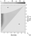
- Fig. 4 is a chart 400 depicting closed loop gain as a function of both edge and corner distance for a 50° overhang according to various embodiments. More particularly, the chart 400 depicts closed loop gain values output by a closed loop Z -axis height correction system as a function of both distance to an edge and distance to a corner for an overhang of 50°.
- the closed loop gain values may be used as feed rate multiplier values, for example.
- the units of the chart 400 are millimeters. As the chart 400 shows, the feed rate amount is relatively consistent at a given distance from the edge, as long as the location is not close to a corner.
- the graph below is only measured inside the boundary 402.
- the lower left triangle shaped boundary 402 of the chart 400 has no data because the distance to the edge is never larger than the distance to the corner for a 90° corner.
- the right side crescent shaped boundary 402 of the chart 400 has no data because the printed part was only 12 mm wide.
- Some embodiments train a machine learning system to determine appropriate feed rates for printing overhangs with any of a variety of overhang angles.
- a machine learning system is trained using induced feed rate and closed loop gain as training data as shown and described in reference to Fig. 4 , together with overhang angle data, as shown and described presently in reference to Figs. 5A and 5B .
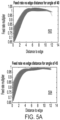
- Figs. 5A and 5B depict charts 502, 504, 506 showing closed loop gain as a function of edge distance for three different overhang angles.
- charts 502, 504, 506 show closed loop gain feed rate multipliers generated by a closed loop Z -axis height correction system as a function of just distance to the edge (but at least 2mm away from a corner) for three different overhang angles.
- Chart 502 is for an overhang angle of 40°
- chart 504 is for an overhang angle of 45°
- chart 506 is for an overhang angle of 50°.
- the range of measurements represented in the charts 502, 504, 506 are due to local variation of drop size, temperature, and distance to edge, along with other noises and fitting errors, but in an embodiment, a machine learning system may be trained using such data to predict a representative curve for each overhang angle, rather than a scatter graph as shown. Such curves may be considered as two-dimensional slices or projections of a three-dimensional surface such as is represented by Figs. 5A and 5B . For example, after training according to the data depicted in chart 502, for an overhang angle of 40°, a trained machine learning system may multiply a nominal feed rate for an edge by about 75%, the average of the training data at a distance to the edge of zero.
- a trained machine learning system may predict feed rate multipliers for overhang features with angles not present in the training data. For example, if trained using the data of charts 502, 504, and 506, which correspond to angles 40°, 45°, and 50°, respectively, a trained machine learning system may predict closed loop Z-axis height correction gain values for overhang features with angles of, by way of non-limiting example, 42°, 46.5°, 48°, etc.
- a machine learning system is trained using training data so as to be able to output feed rates for various features according to spatial toolpath data regarding the features.
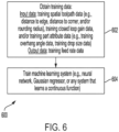
- Fig. 6 illustrates a method of training a machine learning system according to various embodiments.
- Fig. 6 is a flowchart for a method 600 of training a machine learning system for providing a feed rate for three-dimensional printing a part.
- the machine learning system may include a computer-implemented neural network.
- Other embodiments may utilize, by way of non-limiting example, a Gaussian regressor, or any other network or machine learning system that can learn a continuous function.
- the neural network may include an input layer, two hidden nodes, and a linear output layer.
- the neural network may be configured to accept input data, such as spatial toolpath data and closed loop gain data, and provide output data, such as feed rate data.
- the neural network may be trained with training data that includes training input data (e.g., training spatial toolpath data, training closed loop gain data) and training output data (e.g., training feed rate data).
- training input data e.g., training spatial toolpath data, training closed loop gain data
- training output data e.g., training feed rate data
- the neural network may accept an input that includes spatial toolpath data and a closed loop gain value of one, and output a corresponding feed rate, such that if a feature with the spatial toolpath data is printed with the output feed rate, a closed loop Z -axis height correction system would output a gain of one, and the feed rate would not be altered to adjust the Z -axis height.
- method 600 obtains training data.
- the training data may be obtained directly using techniques as shown and described herein in reference to Figs. 3 , 4 , and/or 5, by way of non-limiting examples, and/or indirectly by retrieval from electronic storage, according to various embodiments.
- the training data may include training spatial toolpath data, such as any, or any combination, of: a distance from an edge of the part, a distance to a corner of the part, and/or a rounding radius of a corner.
- the training data may include training closed loop gain data.
- the training data may include training feed rate data. Note that for each printed layer (e.g., as shown and described in reference to Figs. 3 , 4 , and 5 ) there may be hundreds of points (e.g., sets of corresponding toolpath spatial data, closed loop gain data, and feed rate data) generated for the training data, as the closed loop correction is calculated on a 100pm grid according to some closed loop Z-axis height correction systems.
- training feed rate data, training closed loop gain data, and training spatial toolpath data may be sufficient.
- any, or a combination, of the preceding may be included, along with data for one or more additional specific feature types.
- training overhang angle data such as shown and described in reference to Fig. 4 , may be included. That is, overhangs of various angles may be printed and the data obtained used to train the class of overhangs by using the additional input of overhang angle in the training.
- the trained network may predict angles not directly used in the training; this is a great advantage compared to the direct print-and-evaluate prior art technique.
- any, or a combination, of training feed rate data, training closed loop gain data, training spatial toolpath data, and/or training overhang angle data may be included, along with training drop size data (e.g., for drop on demand three-dimensional printing).
- training drop size data e.g., for drop on demand three-dimensional printing
- measured drop size can be included in the training data. This allows the data training to be more accurate even if the drop size varies, which it often does between runs.
- the gain map such as is shown and described herein in reference to Fig.
- the number of inputs e.g., using a parameter for a class of feature types, such as overhang angle and/or drop size
- the number of points used in training is much greater than the number of connections of the neural network topology, overfitting should not occur.
- the number of hidden nodes may be three, by way of non-limiting example.
- method 600 trains the machine learning system using the training data obtained at 602.
- the training may include an iterative process for training a neural network, for example.
- the machine learning system may accept input data, such as spatial toolpath data corresponding to a part or portion thereof, as well as a gain value, such as one, and output a corresponding feed rate.
- input data such as spatial toolpath data corresponding to a part or portion thereof
- a gain value such as one
- the Z -axis height need not be adjusted, because of the training data that it was trained with.
- the closed loop gain value is generally the inverse of the induced feed rate variation, as the nominal unperturbed feed rate chosen for the interior is generally accurate, so the gain should just "undo" the induced variation.
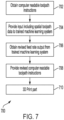
- Fig. 7 is a flowchart for a method 700 of providing a feed rate for three-dimensional printing a part.
- the method 700 may be implemented subsequent to the implementation of the method 600 as shown and described in reference to Fig. 6 , and may utilize the computer-implemented neural network trained according to the method 600.
- the method 700 includes obtaining computer readable toolpath instructions for the part.
- the computer readable instructions may be included in a GCode file, by way of non-limiting example.
- the toolpath instructions may direct a tool to follow a toolpath and extrude or otherwise deposit material along some or all of the toolpath to produce one or more layers to produce the part.
- the toolpath instructions may specify a nominal feed rate for a toolpath segment (e.g., a local portion of a longer toolpath) and spatial toolpath data of the toolpath segment.
- the method 700 includes providing an input that includes the spatial toolpath data to a trained machine learning system.
- the trained machine learning system may be generated as shown and described herein in reference to Fig. 6 , for example.
- the trained machine learning system may be trained using training data, such as training spatial toolpath data, training closed loop gain data, and training feed rate data, e.g., as described herein in reference to Figs. 5A and 5B .
- the method 700 includes obtaining a revised feed rate for the toolpath segment output from the trained machine learning system in response to the input of 704.
- the revised feed rate may be the same as or different from the nominal feed rate for the toolpath segment.
- the method 700 includes providing revised computer readable toolpath instructions.
- the revised computer readable toolpath instructions may include the revised feed rate for the toolpath segment, e.g., replacing the nominal feed rate for all or part of the toolpath segment.
- the revised computer readable toolpath instructions may be in the form of GCode, by way of non-limiting example.
- the instructions may be provided to a three-dimensional printer, for storage in persistent electronic memory, or over a network, for example.
- the method 700 includes printing the part using the revised computer readable toolpath instructions.
- the part may be printed using any of a variety of three-dimensional printers and in any of a variety of materials.
- some embodiments may train a machine learning system to print layers on top of layers that have been printed with fewer errors using the techniques disclosed herein.
- an initial layer may be printed using closed loop Z -axis height correction gain values provided by a machine learning system that has been trained to print using training data obtained by printing an initial layer
- a subsequent layer may be printed using closed loop Z -axis height correction gain values provided by a machine learning system that has been trained to print using training data obtained by printing a layer on top of such a first layer.
- Such embodiments may account for the fact that an initial layer printed using the techniques disclosed herein will be more accurate than an initial layer printed without using the techniques disclosed herein.
- a subsequent layer may be printed using a trained machine learning system that has been trained to print on top of such a more accurate initial layer.
- some embodiments may be further iteratively trained to print on top of previous layers printed using a machine learning system trained according to a previous iteration.
- Some embodiments may provide a pre-trained machine learning system, where the pre-trained machine learning system has been pre-trained for a first feature or set of features using training data obtained from a particular three-dimensional printer or class of three-dimensional printers. Some embodiments may be additionally trained for an additional feature or set of features using training data obtained from the same three-dimensional printer or class of three-dimensional printers, or from a different three-dimensional printer or class of three-dimensional printers.
- the computer programs can exist in a variety of forms both active and inactive.
- the computer programs can exist as software program(s) comprised of program instructions in source code, object code, executable code or other formats; firmware program(s), or hardware description language (HDL) files.
- Any of the above can be embodied on a transitory or non-transitory computer readable medium, which includes storage devices and signals, in compressed or uncompressed form.
- Exemplary computer readable storage devices include conventional computer system RAM (random access memory), ROM (read-only memory), EPROM (erasable, programmable ROM), EEPROM (electrically erasable, programmable ROM), and magnetic or optical disks or tapes.
- These computer readable program instructions may be provided to a processor of a general-purpose computer, special purpose computer, or other programmable data processing apparatus, to produce a machine, such that the instructions, which execute via the processor of the computer or other programmable data processing apparatus, create means for implementing the functions/acts specified in the flowchart and/or block diagram block or blocks.
- These computer readable program instructions may also be stored in a computer readable storage medium that can direct a computer, a programmable data processing apparatus, and/or other devices to function in a particular manner, such that the computer readable storage medium having instructions stored therein comprises an article of manufacture including instructions which implement aspects of the function/act specified in the flowchart and/or block diagram block or blocks.
- the computer readable program instructions may be assembler instructions, instruction-set-architecture (ISA) instructions, machine instructions, machine dependent instructions, microcode, firmware instructions, state-setting data, configuration data for integrated circuitry, or either source code or object code written in any combination of one or more programming languages, including an object oriented programming language such as Smalltalk, C++, or the like, and procedural programming languages, such as the C programming language or similar programming languages.
- the computer readable program instructions may execute entirely on a user's computer, partly on the user's computer, as a stand-alone software package, partly on the user's computer and partly on a remote computer or entirely on the remote computer or server.
- the terms “A or B” and “A and/or B” are intended to encompass A, B, or ⁇ A and B ⁇ . Further, the terms “A, B, or C” and “A, B, and/or C” are intended to encompass single items, pairs of items, or all items, that is, all of: A, B, C, ⁇ A and B ⁇ , ⁇ A and C ⁇ , ⁇ B and C ⁇ , and ⁇ A and B and C ⁇ .
- the term “or” as used herein means “and/or.”
Landscapes
- Engineering & Computer Science (AREA)
- Manufacturing & Machinery (AREA)
- Materials Engineering (AREA)
- Chemical & Material Sciences (AREA)
- Physics & Mathematics (AREA)
- Theoretical Computer Science (AREA)
- Software Systems (AREA)
- General Physics & Mathematics (AREA)
- Artificial Intelligence (AREA)
- Mathematical Physics (AREA)
- Computing Systems (AREA)
- Evolutionary Computation (AREA)
- Data Mining & Analysis (AREA)
- Automation & Control Theory (AREA)
- General Engineering & Computer Science (AREA)
- Medical Informatics (AREA)
- Human Computer Interaction (AREA)
- Computer Vision & Pattern Recognition (AREA)
- Mechanical Engineering (AREA)
- Optics & Photonics (AREA)
- Health & Medical Sciences (AREA)
- Life Sciences & Earth Sciences (AREA)
- Biomedical Technology (AREA)
- Biophysics (AREA)
- Computational Linguistics (AREA)
- General Health & Medical Sciences (AREA)
- Molecular Biology (AREA)
Applications Claiming Priority (1)
| Application Number | Priority Date | Filing Date | Title |
|---|---|---|---|
| US18/168,126 US20240272612A1 (en) | 2023-02-13 | 2023-02-13 | Machine learning feature feed rates for 3d printing |
Publications (1)
| Publication Number | Publication Date |
|---|---|
| EP4414105A1 true EP4414105A1 (fr) | 2024-08-14 |
Family
ID=89662248
Family Applications (1)
| Application Number | Title | Priority Date | Filing Date |
|---|---|---|---|
| EP24153007.0A Pending EP4414105A1 (fr) | 2023-02-13 | 2024-01-19 | Débits d'alimentation de caractéristiques d'apprentissage automatique pour impression 3d |
Country Status (3)
| Country | Link |
|---|---|
| US (1) | US20240272612A1 (fr) |
| EP (1) | EP4414105A1 (fr) |
| JP (1) | JP2024114630A (fr) |
Families Citing this family (1)
| Publication number | Priority date | Publication date | Assignee | Title |
|---|---|---|---|---|
| WO2025155540A1 (fr) * | 2024-01-19 | 2025-07-24 | 3D Systems, Inc. | Régulation de débit dans un procédé de dépôt par extrusion |
Citations (3)
| Publication number | Priority date | Publication date | Assignee | Title |
|---|---|---|---|---|
| US9827717B2 (en) * | 2014-08-15 | 2017-11-28 | University Of Southern California | Statistical predictive modeling and compensation of geometric deviations of 3D printed products |
| EP3800539A1 (fr) * | 2019-10-01 | 2021-04-07 | Palo Alto Research Center Incorporated | Procédé et système pour faire fonctionner une imprimante d'objets en trois dimensions (3d) à éjection de gouttes de métal pour compenser les variations de taille de goutte |
| US20220414380A1 (en) * | 2021-06-24 | 2022-12-29 | Palo Alto Research Center Incorporated | Characterizing liquid reflective surfaces in 3d liquid metal printing |
Family Cites Families (9)
| Publication number | Priority date | Publication date | Assignee | Title |
|---|---|---|---|---|
| SI21200A (sl) * | 2002-03-27 | 2003-10-31 | Jože Balič | Cnc upravljalna enota za krmiljenje obdelovalnih centrov s sposobnostjo učenja |
| JP6457563B2 (ja) * | 2017-01-24 | 2019-01-23 | ファナック株式会社 | 数値制御装置及び機械学習装置 |
| US10234848B2 (en) * | 2017-05-24 | 2019-03-19 | Relativity Space, Inc. | Real-time adaptive control of additive manufacturing processes using machine learning |
| WO2019018436A1 (fr) * | 2017-07-17 | 2019-01-24 | Desktop Metal, Inc. | Fabrication additive à l'aide de débits d'alimentation de matériau de construction variables |
| FR3103124B1 (fr) * | 2019-11-19 | 2022-05-13 | Addup | Procédé de détermination de paramètres de fabrication additive |
| US11285673B2 (en) * | 2019-12-17 | 2022-03-29 | Northrop Grumman Systems Corporation | Machine-learning-based additive manufacturing using manufacturing data |
| US11782396B2 (en) * | 2020-06-22 | 2023-10-10 | Autodesk, Inc. | Toolpath generation by reinforcement learning for computer aided manufacturing |
| US20220347930A1 (en) * | 2021-04-30 | 2022-11-03 | Ahead Wind Inc. | Simulation, correction, and digitalization during operation of an additive manufacturing system |
| GB202204072D0 (en) * | 2022-03-23 | 2022-05-04 | Cambridge Entpr Ltd | Method, apparatus and system for closed-loop control of a manufacturing process |
-
2023
- 2023-02-13 US US18/168,126 patent/US20240272612A1/en active Pending
-
2024
- 2024-01-19 EP EP24153007.0A patent/EP4414105A1/fr active Pending
- 2024-01-29 JP JP2024011012A patent/JP2024114630A/ja active Pending
Patent Citations (3)
| Publication number | Priority date | Publication date | Assignee | Title |
|---|---|---|---|---|
| US9827717B2 (en) * | 2014-08-15 | 2017-11-28 | University Of Southern California | Statistical predictive modeling and compensation of geometric deviations of 3D printed products |
| EP3800539A1 (fr) * | 2019-10-01 | 2021-04-07 | Palo Alto Research Center Incorporated | Procédé et système pour faire fonctionner une imprimante d'objets en trois dimensions (3d) à éjection de gouttes de métal pour compenser les variations de taille de goutte |
| US20220414380A1 (en) * | 2021-06-24 | 2022-12-29 | Palo Alto Research Center Incorporated | Characterizing liquid reflective surfaces in 3d liquid metal printing |
Also Published As
| Publication number | Publication date |
|---|---|
| US20240272612A1 (en) | 2024-08-15 |
| JP2024114630A (ja) | 2024-08-23 |
Similar Documents
| Publication | Publication Date | Title |
|---|---|---|
| Druzgalski et al. | Process optimization of complex geometries using feed forward control for laser powder bed fusion additive manufacturing | |
| US10769324B2 (en) | Intelligent additive manufacturing | |
| CN112118949B (zh) | 增材制造中用于人工智能反馈控制的系统、方法和介质 | |
| US10661499B2 (en) | Platen planarizing process for additive manufacturing system | |
| US20240239050A1 (en) | Method, device, and electronic device for controlling 3d printing | |
| EP4249153A1 (fr) | Outil de visualisation de trajet de balayage et de prédiction de distribution de défauts | |
| EP3689508B1 (fr) | Système d'impression 3d comprenant un dispositif d'imagerie | |
| Wasserfall et al. | Adaptive slicing for the FDM process revisited | |
| US10518356B2 (en) | Methods and apparatus for generating additive manufacturing scan paths using thermal and strain modeling | |
| CN110978503B (zh) | 积层制造系统与方法及特征撷取方法 | |
| US20180193954A1 (en) | Systems and methods for controlling microstructure of additively manufactured components | |
| US10549519B2 (en) | Systems and methods for calibrating additive manufacturing operations based on energy density | |
| EP4414105A1 (fr) | Débits d'alimentation de caractéristiques d'apprentissage automatique pour impression 3d | |
| CN117565402B (zh) | 3d打印控制执行方法、系统及3d打印设备 | |
| US12591220B2 (en) | Systems and methods for using wire printing process data to predict material properties and part quality | |
| US11886759B2 (en) | Method and system for operating a metal drop ejecting three-dimensional (3D) object printer to compensate for drop size variations | |
| US10884396B2 (en) | Sensor based smart segmentation | |
| EP3991947B1 (fr) | Surveillance et contrôle des processus de fabrication additive par voie optique en cours de processus | |
| US20200039145A1 (en) | Powder-Bed-Based Additive Manufacture of a Workpiece | |
| CN112828311A (zh) | 一种基于实时三维检测的金属增材制造在线轨迹调整方法 | |
| WO2022086554A1 (fr) | Génération de carte d'agent | |
| CN118003630A (zh) | 基于增材制造和视觉技术的熔池可变宽度打印方法、系统、终端及介质 | |
| US20230245272A1 (en) | Thermal image generation |
Legal Events
| Date | Code | Title | Description |
|---|---|---|---|
| PUAI | Public reference made under article 153(3) epc to a published international application that has entered the european phase |
Free format text: ORIGINAL CODE: 0009012 |
|
| STAA | Information on the status of an ep patent application or granted ep patent |
Free format text: STATUS: THE APPLICATION HAS BEEN PUBLISHED |
|
| AK | Designated contracting states |
Kind code of ref document: A1 Designated state(s): AL AT BE BG CH CY CZ DE DK EE ES FI FR GB GR HR HU IE IS IT LI LT LU LV MC ME MK MT NL NO PL PT RO RS SE SI SK SM TR |
|
| STAA | Information on the status of an ep patent application or granted ep patent |
Free format text: STATUS: REQUEST FOR EXAMINATION WAS MADE |
|
| 17P | Request for examination filed |
Effective date: 20250214 |