EP4414286A2 - Sicherheitsventil für mehrwegflasche, flaschenmanschette und verfahren zum verschliessen einer mehrwegflasche - Google Patents
Sicherheitsventil für mehrwegflasche, flaschenmanschette und verfahren zum verschliessen einer mehrwegflasche Download PDFInfo
- Publication number
- EP4414286A2 EP4414286A2 EP23211470.2A EP23211470A EP4414286A2 EP 4414286 A2 EP4414286 A2 EP 4414286A2 EP 23211470 A EP23211470 A EP 23211470A EP 4414286 A2 EP4414286 A2 EP 4414286A2
- Authority
- EP
- European Patent Office
- Prior art keywords
- valve
- key
- actuator
- security
- bottle
- Prior art date
- Legal status (The legal status is an assumption and is not a legal conclusion. Google has not performed a legal analysis and makes no representation as to the accuracy of the status listed.)
- Pending
Links
Images



























Classifications
-
- B—PERFORMING OPERATIONS; TRANSPORTING
- B65—CONVEYING; PACKING; STORING; HANDLING THIN OR FILAMENTARY MATERIAL
- B65D—CONTAINERS FOR STORAGE OR TRANSPORT OF ARTICLES OR MATERIALS, e.g. BAGS, BARRELS, BOTTLES, BOXES, CANS, CARTONS, CRATES, DRUMS, JARS, TANKS, HOPPERS, FORWARDING CONTAINERS; ACCESSORIES, CLOSURES, OR FITTINGS THEREFOR; PACKAGING ELEMENTS; PACKAGES
- B65D47/00—Closures with filling and discharging, or with discharging, devices
- B65D47/04—Closures with discharging devices other than pumps
- B65D47/20—Closures with discharging devices other than pumps comprising hand-operated members for controlling discharge
- B65D47/24—Closures with discharging devices other than pumps comprising hand-operated members for controlling discharge with poppet valves or lift valves, i.e. valves opening or closing a passageway by a relative motion substantially perpendicular to the plane of the seat
- B65D47/248—Closures with discharging devices other than pumps comprising hand-operated members for controlling discharge with poppet valves or lift valves, i.e. valves opening or closing a passageway by a relative motion substantially perpendicular to the plane of the seat the valve being opened or closed by imparting a motion to the valve stem
-
- F—MECHANICAL ENGINEERING; LIGHTING; HEATING; WEAPONS; BLASTING
- F16—ENGINEERING ELEMENTS AND UNITS; GENERAL MEASURES FOR PRODUCING AND MAINTAINING EFFECTIVE FUNCTIONING OF MACHINES OR INSTALLATIONS; THERMAL INSULATION IN GENERAL
- F16K—VALVES; TAPS; COCKS; ACTUATING-FLOATS; DEVICES FOR VENTING OR AERATING
- F16K35/00—Means to prevent accidental or unauthorised actuation
- F16K35/08—Means to prevent accidental or unauthorised actuation requiring setting according to a code, e.g. permutation locks
-
- B—PERFORMING OPERATIONS; TRANSPORTING
- B65—CONVEYING; PACKING; STORING; HANDLING THIN OR FILAMENTARY MATERIAL
- B65D—CONTAINERS FOR STORAGE OR TRANSPORT OF ARTICLES OR MATERIALS, e.g. BAGS, BARRELS, BOTTLES, BOXES, CANS, CARTONS, CRATES, DRUMS, JARS, TANKS, HOPPERS, FORWARDING CONTAINERS; ACCESSORIES, CLOSURES, OR FITTINGS THEREFOR; PACKAGING ELEMENTS; PACKAGES
- B65D49/00—Arrangements or devices for preventing refilling of containers
-
- B—PERFORMING OPERATIONS; TRANSPORTING
- B65—CONVEYING; PACKING; STORING; HANDLING THIN OR FILAMENTARY MATERIAL
- B65D—CONTAINERS FOR STORAGE OR TRANSPORT OF ARTICLES OR MATERIALS, e.g. BAGS, BARRELS, BOTTLES, BOXES, CANS, CARTONS, CRATES, DRUMS, JARS, TANKS, HOPPERS, FORWARDING CONTAINERS; ACCESSORIES, CLOSURES, OR FITTINGS THEREFOR; PACKAGING ELEMENTS; PACKAGES
- B65D50/00—Closures with means for discouraging unauthorised opening or removal thereof, with or without indicating means, e.g. child-proof closures
- B65D50/02—Closures with means for discouraging unauthorised opening or removal thereof, with or without indicating means, e.g. child-proof closures openable or removable by the combination of plural actions
- B65D50/06—Closures with means for discouraging unauthorised opening or removal thereof, with or without indicating means, e.g. child-proof closures openable or removable by the combination of plural actions requiring the combination of different actions in succession
-
- B—PERFORMING OPERATIONS; TRANSPORTING
- B67—OPENING, CLOSING OR CLEANING BOTTLES, JARS OR SIMILAR CONTAINERS; LIQUID HANDLING
- B67D—DISPENSING, DELIVERING OR TRANSFERRING LIQUIDS, NOT OTHERWISE PROVIDED FOR
- B67D3/00—Apparatus or devices for controlling flow of liquids under gravity from storage containers for dispensing purposes
- B67D3/02—Liquid-dispensing valves having operating members arranged to be pressed upwards, e.g. by the rims of receptacles held below the delivery orifice
Definitions
- the present invention relates to a security valve designed for use in returnable bottles, a bottle collar to be applied thereon, and a process for plugging a returnable bottle.
- Bottles can be of the type that is placed on dispensers, or they can be returnable bottles which can be discharged manually or by other means
- the contents of the bottles can be for human ingestion such as water, juice, or any other drinkable liquid, but alternatively the contents can be any other non-drinkable liquids such as chemicals, caustics, or liquid fuels.
- VBR Valve Returnable Bottle Valve
- the security valve that in this document will be called VBR Valve (Returnable Bottle Valve) includes three embodiments: a) a valve provided with an automatic actuator; b) a valve provided with a manual actuator and c) a valve not provided with an actuator.
- EP 2925666B1 relates to a container closure for overhead emptying, which has a closure cap (1) for placing on a container neck, the closure cap having an approximately cylindrical cap jacket (2) and a circular disk-shaped head plate (3) which has a central opening (4), from which an inward directed pipe socket (5), in which a sealing plug (6) is locked, the sealing plug (6) also being able to be brought into locking engagement with a drain pipe and moved into the interior of the container.
- the valve is disposable; the container is returned to the factory open with associated risks of contamination or insect entry; the container can be reused by others, since, by placing a new cap, it can be marketed without quality control of the contents.
- EP0706952A1 discloses a tamper-evident/non-refillable type of closure for a bottle that comprises a cylindrical tube (G) which fits around and is secured to the outer surface of the neck of the bottle (H), a valve seat (D) which forms a seal with the neck of the bottle (H), a valve (C) which makes a seal with the valve seat (D), two cylindrical spheres or marbles (E) and (F).
- the closure is not a reusable one, but rather a disposable closure.
- GB2329892A describes a closure for a bottle has an end wall 4, an outer annular wall 5 with an internal bead 7, an inner annular wall 6 for receiving a dispensing tube, and a tamper evident portion 14 which is broken by the dispensing tube when the bottle is inserted in a water fountain type dispenser.
- the tamper evident portion may be a diaphragm with tear lines 16 and petal shaped parts 15, and may be located in the plane of the end wall.
- the closure may have a stopper 9 which can be moved by the dispensing tube between a closed position in contact with the inner wall, and an open dispensing position remote from the inner wall.
- the closure may also have a tear line 17 in the outer wall, to enable removal of the closure after use. and a tamperproof ring 23 attached by bridges 24 to the outer wall.
- the valve in the cited document is disposable, the water gallon is returned to the factory and can be reused by unauthorized others.
- GB2366287A discloses a tamper-evident anti-refill closure 10 comprises a sleeve 20 and a valve seat body 30, the sleeve being adapted to lie around the mouth 15 of a container and being provided with at least one inwardly projecting resilient means 25 engageble with an outer lip portion of the container mouth whilst the valve seat body is at least partially receivable within the neck portion of the container, the sleeve at least partially surrounding the valve seat body.
- the sleeve may further comprise a pouring outlet portion 55 which may have an extending lip 60.
- the closure may further comprise a tubular body 65, a bore of which is closed by an outer face wall 85, the tubular body being connected to the inner surface of the sleeve by webs 75.
- the tubular body may have a circumferential brim portion 90.
- the sleeve may be fitted with a plurality of ribs or ridges 100 which co-operate with raised ribs or ridges on the outer surface of the container to prevent the sleeve being rotated about the container neck.
- the valve seat member may comprise a tubular portion, having one end 120 closed except for a circular aperture, which may have interference means provided to engage with the inside of the container whilst the other end may comprise an annular trough which in use prevents the insertion of foreign objects into the tubular member by providing a non-linear fluid flow path 410 ( fig 9 ).
- a second invention is disclosed comprising a first sleeve and a second, outer sleeve that is rotatable about the first.
- the first sleeve may be fixed upon the container neck, may further comprise valve means and may be provided with a cap, there being a frangible connection between the two.
- the valve of this document cannot be reused because it is disposable, the same as the container.
- Document AR056057A1 describes a tamper-resistant lid for returnable water bottles. It consists of a circular portion subdivided into 6 equal portions housed in a central depression. These 6 petals that make up the center of the lid will tear from the center towards the walls in a controlled manner once the lid - placed on the bottle - is pierced by the sword of the dispenser. When this happens the lid will be completely unusable.
- the lid is concave in shape and contains thin, pronounced and sharp concentric lips throughout its circumference, which is why it adapts to all types of spouts and corrects imperfections that they may have since when the lid comes into contact with the spout of the drum Both snap together and the thin edges of the lid deform, thus guaranteeing a perfect closure.
- the lid is disposable and does not guarantee that the bottle will be returned to the plant with the lid on and does not prevent unauthorized refilling.
- the present invention relates to 1) a security valve provided with an automatic actuator, 2) a valve provided with a manual actuator, 3) a valve not provided with an actuator, for plugging a returnable bottle or drum, 4) a compact valve and a bottle collar.
- the valve with an automatic actuator is designed to plug bottles to be placed on dispensers having a probe that opens the valve to release the liquid contained within the bottle and when removing the valve from the dispenser, the valve remains safely closed.
- the valve with a manual actuator is designed to be used for bottles to be placed on dispensers without a probe, and the manual actuator is used to open the valve and close it safely.
- the valve without an actuator i.e., the actuator-free valve, is designed for returnable bottles and drums containing non-drinking liquids.
- the compact valve has fewer parts.
- the valve includes a tamper-proof security mechanism, and the process includes etching an opening code on the outer surface of the valve, where the valve is released for its removal from the bottle through a 3-rotations unlocking maneuver of the security mechanism, with a first rotation in one direction through a first determined number of angular degrees, followed by a second rotation in the opposite direction through a second determined number of angular degrees, and a third rotation in the first direction through a third determined number of angular degrees, and where the three numbers of rotation degrees are known by decrypting said opening code.
- the opening code is presented as a barcode and in an alternative embodiment as a two-dimensional QR code, both known in the art.
- the VBR valve of the present invention has been designed in four different embodiments: a) a VBR valve with an automatic actuator, b) a VBR valve with a manual actuator, c) a VBR valve without an actuator and d) a compact valve.
- VBR valve with an automatic actuator was designed to be used in bottles that will be placed on dispensers that have a central probe in the housing, that normally pierces the bottle lid when placed upside down on the dispenser.
- VBR valve with a manual actuator is designed to be used in bottles that will be placed on dispensers that do not have a central probe.
- the VBR valve without an actuator is designed for use in bottles that are not placed on dispensers and contain hazardous liquids (caustic or flammable chemicals) that require a tamper-proof closure.
- VBR_C compact valve was designed in such a way that it comprises fewer parts and more reliable locking when removing the drum from the dispenser.
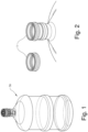
- Figure 1 shows the security VBR valve with an automatic actuator of the present invention placed on a returnable bottle that is of the type used in water dispensers.
- the bottles are delivered with a disposable lid having an inner closure that opens when the bottle is placed in the dispenser. Its opening is by means of a hollow plastic bolt (probe) present in the dispenser, through which the water flows by gravity.
- a hollow plastic bolt probe
- the disposable lid is not reliable because it is not designed to be tamper-proof after use.
- VBR valve allows the manufacturer to use its entire inventory of bottles, without the need of replacing them with new bottles with a special design where a bottle collar is placed or welded. In this sense, the VBR valve adapts to all current bottle models and sizes found on the market.
- the security VBR valve was designed to achieve the following objectives:
- the present invention assembly is made up of the following two elements:
- Figure 1 shows the returnable bottle with the VBR valve 2 with an automatic actuator of the present invention.
- Figure 2 shows the collar 1 that, with the aim of applying any of the valves of the present invention to an existing conventional bottle, is welded to the bottle neck by ultrasound, or alternatively, by laser, high frequency, roto-fusion, or by chemical bonding.
- the collar allows the VBR valve to be compatible with the different manufacturing tolerances of bottles from different manufacturers, enabling the use of a retaining ring to fix the removable VBR valve to the bottle.
- a tracking code 46 see Figure 2A
- This code is used to trace the bottle throughout its useful life.
- the code consists of a barcode and in another embodiment, it consists of a two-dimensional QR code, both known in the art.
- the bottle with its collar 1 is sanitized using the same methods and steps currently used with the traditional returnable bottles.
- valves of the present invention to bottles that are manufactured comprising the collar 1 is contemplated without the need to carry out the above described process.
- Figure 2B shows the head of a VBR valve 2 with an automatic actuator.
- FIG. 3 illustrates a removable security VBR valve with an automatic actuator 2 which is removed to fill the bottle and consists of several parts whose functions will be described on the following pages.
- the security VBR valve 2 includes a security code 51 that is independent of the collar code 1 and serves to identify the VBR valve at the plant and enables its opening. Once the VBR valve 2 is removed and sanitized, it is placed in any already refilled bottle, updating the security database with the VBR valve code of each bottle.
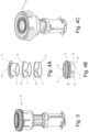
- Figures 4A and 4B show that a security VBR valve with an automatic actuator comprises a series of cylinders 3 having a single position at which the VBR valve can be removed.
- This combination is set at the factory with an automatic machine that can combine the cylinders 3 into one of over 42,000 positions. This number of combinations allows the machine to be programmed to assign a unique combination for each customer and different codes to each of their bottles.
- the machine prints the security code 51 on its outer surface in the form of a barcode or as a two-dimensional QR that is entered in a computer system, which must be queried to know the bottle opening key, since it is inaccessible encrypted.
- This query is made by the customer's removing machine by reading the key encrypted in the barcode or in the two-dimensional QR code using an optical reader arranged for such purpose and comparing the result with the code database stored on a computer system server adapted for such purpose.
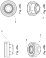
- Figure 4C shows code 51 etched on the lid of a VBR valve with an automatic actuator.
- Figures 4A and 4B also illustrate the safety VBR valve 2 comprising three concentrically located disks 4, 5, 6, which can rotate independently and freely and are actuated from the innermost disk 4.
- the only disk visible from the outside 4, transmits the rotation to the disk 5 through a step 8 hidden on its outer surface while, through its step 8, disk 5 will transmit the movement to disk 6.
- the "key" slot 7 that is seen at the bottom of the disks is carved at a given and variable angle with respect to the rotation step 8 of each slot, that is, each "key” slot 7 is carved at a different angle from its dick step 8.
- the three key disks 4, 5, 6 are machine-carved at the time of assembly, and a code identifying the VBR valve is etched on its body registering the access data on the computer system server at that time. This angle is selected by the computer program hosted by the system server and depends on the codes to be assigned according to the customer and the automatically assigned sequence number. The customer number is unique for each customer and the sequence number is random.
- the first step is to locate the key disk 4 at a known position, and this is done by rotating the key disk 4 counterclockwise. When moving it in that direction, it will come into contact with the key disk 5 and will rotate it in the same direction, until the key disk 5 encounters the key disk 6 and rotates it in the same direction until the key disk 6 encounters the septum 20 of the sleeve 14, which cannot rotate. In this way, the key disk 4 will not rotate anymore. This will be the starting position to begin placing the keys into position.
- Figure 6 illustrates the situation in which the key disks 4, 5, 6 will be in the removing position when the "key" slots 7 of the 3 key disks coincide, which will occur if each disk is placed in its correct position.
- To place the key disks in the correct position it is necessary to know their code made up of three numbers representing the angle at which the key was etched on each disk. The code is not accessible to anyone as it is etched on the surface of the lid 9 of key box 16 in an encrypted manner, which is unique for each customer. The same cryptography can represent different keys depending on the customer.
- the key disk 6 is first brought into position in a certain rotation direction and angle according to how this "key" slot 7 was carved with respect to its step 8.
- this disk is rotated in the opposite direction by dragging the key disk 5 though a certain angle with respect to its step 8 according to its code, and finally it is rotated in the opposite direction to place the key disk 4 in its correct position. If the process is done correctly, the three "key" slots 7 will be perfectly aligned.
- Figure 7 shows the components involved in the mechanism that secures a VBR valve with an automatic actuator 2 inside the bottle and prevents its disassembly.
- the anchoring mechanism is formed by the bottle collar 1, the position locks 18, the sleeve 14 and its ribs 15, the key box 16 and a locking basket 17.
- the sleeve 14 is the mobile part that moves longitudinally to move the position locks 18 with its ribs 15 outwards when the VBR valve 2 is inside the bottle.
- Figure 8A shows the key box 16, which in its lower portion provides guides 19 that house the position locks 18. Said guides 19 only allow a radial movement of the locks 18, and provide stops 12 at their outer end limiting the outward movement of the position locks 18.
- Figure 8B shows the locks 18 in position on the guides 19.
- Figure 9A shows the position locks 18 outwardly moved pushed by the ribs 15 of the sleeve 14.
- Figure 9B shows locks 18 moved towards the center, pushed by the locking basket 17 until they touch the sleeve 14 as it moves upwards along with its ribs 15, which in that position no longer press the locks 18.
- Figures 11A to 11C show, in three steps, the way in which the locking basket 17 enters and remains locked when the key box 16 enters the bottle collar 1 (for clarity only the essential components are represented).
- Figure 11A shows the collar 1, the locking basket 17 and the key box 16 their locks 18 moved towards the center.
- Figure 11B the locking basket 17 has already entered collar 1 until resting on it.
- Figure 11C shows the entry of the key box 16, and how its tapered walls push the lips L of the locking basket 17 outwards, causing them to prevent the key box 16 from moving when locking it at the PBS point.
- Figure 12 shows in detail that the locking basket 17 has lips L with inner ribs, where the lips L can move outwards due to their elasticity.
- Figure 13 shows in detail the geometry of the sleeve 14 with its notable elements: the anti-rotation septum 22 and the security septum 20, the seal housings 21A and 21B, the ribs 15, the vertical guide 34 and the horizontal guide 25.
- Figures 14A and 14B show how the key box 16 enters, the outer walls of which are conical, and then, upon reaching its locking position, the key box 16 rests on the upper portion of the locking basket 17, which in turn pushes with its walls the lips L of the locking basket 17, causing them to open to a diameter greater than the bore of the bottle collar 1. So, when trying to remove the VBR valve 2, these lips L will exert forces on the inner surface 13 of the bottle collar at the PBS point. This causes the basket 17 to be trapped externally and internally by the bottle collar 1.
- Figures 15A to 15F illustrate the movements necessary to remove a VBR valve with an automatic actuator from the container.
- Figure 15A shows the PBS point where a first locking interference is established, produced by the lips L being moved outwards by the outer tapered faces of the key box 16, preventing the locking basket 17 from being removed from the collar 1. It also shows the PBI point where the second locking interference is generated between the locks 18 and the locking basket 17 when the locks 18 are moved outwards by the ribs 15 of the sleeve 14. Both PBS and PBI points prevent the key box 16 from passing through the interior of the locking basket 17, and therefore prevent disassembling the VBR valve.
- the sleeve 14 can be raised, as seen in Figure 15D and, in this way, cause the rib 15 of the sleeve 14 to stop pushing the locks 18 outwards.
- the sleeve 14 By continuing to pull the sleeve 14 upwards, due to the tapered profile of the locks 18, they move towards the center by exerting a force on the lower edge of the basket 17, also allowing the PBI point to be released. This allows the keys box 16 to pass through the sleeve 14, as seen in Figure 15E .
- Figure 16 shows the box lid 9 being welded to the key box 16 at the contact surface A. This weld is what keeps the three key disks 4, 5 and 6 in position.
- the key box 16 must be waterproof sealed and to do so it has a series of elastic rings or O-rings that are detailed below.
- An O-ring 11 maintains the tightness of the key box 16 with respect to the container exterior, sealing the connection between the key disk 4 and the box lid 9.
- a second O-ring 26 located between the tight housing 21B of the sleeve 14 and the key disk 4 inner wall maintains the tightness with respect to the exterior.
- a third O-ring 27 placed between the inner wall of the key box 16 and the tight housing 21A of the sleeve 14 provides tightness of the key box 16 with respect to the container interior.
- a fourth O-ring 10 provides tightness of the VBR valve with respect to the container collar 1.
- O-ring 10 is in the housing B of the box lid 9 and the bottle inner wall of the collar 1.
- a fifth O-ring 28 is shown in Figure 17 , which seals the main liquid outlet, and is the one that must be moved with the opening plunger 29.
- O-ring 28 is in the cavity C of the plunger 29 and the sealing is achieved by contacting against the inner wall of the sleeve 14.
- FIG. 17 shows the spring 30 of the plunger 29 that maintains the VBR valve sealed, and the stop 31 that maintains the spring 30 in its position.
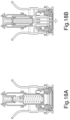
- Figure 18 illustrates the liquid outlet system to the dispenser in the VBR valve with an automatic actuator.
- the VBR valve In Figure 18A the VBR valve is closed, in Figure 18B the VBR valve is open allowing the liquid to come out of the container.
- Figure 19 shows from left to right the assembling sequence (A), and from right to left, the disassembling sequence (B) of the VBR valve 2.
- VBR valve with an automatic actuator 2 has been designed for use with dispensers having a probe and it is exclusive for use with bottles since commercial drinking water dispensers have a probe that operates on the VBR valve.
- Figure 20 shows the dispenser cradle or receptacle 32 on which the bottle rests
- Figure 21 shows the position of the VBR valve 2 with an automatic actuator prior to its insertion into the dispenser cradle 32.
- Figure 22 is a cross-sectional view of a VBR valve with an automatic actuator 2 before entering the dispenser;
- Figure 23 shows the way in which the dispenser probe 33 opens the VBR valve 2 when placing the bottle on the dispenser receptacle 32, thereby allowing the liquid to exit. When the bottle is removed from the dispenser, the probe 33 comes out and the VBR valve 2 closes again.
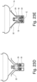
- Figures 23A to 23E show the opening operation sequence of a VBR valve with an automatic actuator 2 in a dispenser.
- Figure 23A shows the elements of a VBR valve with an automatic actuator before placing the bottle in the dispenser.
- Valve 2 has two water outlets 1B that, because the bottle 1A has not yet entered the dispenser cradle 32, are locked by the plunger 29 and its closing O-ring 28.
- the probe 33 has two water inlet holes 1C and the water outlet entry 1D at its base.
- Figure 23B shows the VBR valve with an automatic actuator 2 when the bottle is positioned on the dispenser.
- Bottle 1A is positioned on the dispenser cradle 32, the VBR valve 2 is closed, and the internal spring maintains the plunger 29 in the closed position.
- Figure 23C shows the VBR valve with an automatic actuator 2 when the bottle begins to descend onto the dispenser.
- Bottle 1A descends and the dispenser probe 33 begins to enter the VBR valve 2.
- Figure 23D shows the VBR valve with an automatic actuator 2 when the bottle descends further onto the dispenser. The bottle continues to descend and starts to push the closing plunger of the VBR valve 2 into the bottle.
- Figure 23E shows the VBR valve with an automatic actuator 2 reaching the lowest point inside the dispenser.
- Bottle 1A continues to descend, the plunger 29 is pushed to its open position, the water outlets 1B are released and enters the probe through point 1C and flows towards the outlet 1D of the dispenser probe 33.
- Tamper-proof system preventing refilling by others
- This section describes the mechanism that allows a bottle to be filled and emptied only once, having to return to the bottling plant for refilling.
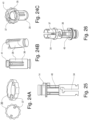
- Figure 24 A shows the security ring 35 with its bolts 37; said bolts 37 will engage with the plunger 29 when moving within the guides 41 of the plunger 29 shown in Figure 24B . Due to the limited shape and length of the guides 41, the security ring 35 can only rotate on the plunger 29 at a certain angle, as can be seen in Figure 24C . In turn, when placing the plunger 29 inside the sleeve 14, the ribs 36 of the plunger 29 will be located within the internal longitudinal guide 40 of the sleeve 14 shown in Figure 25 , preventing the plunger 29 from rotating with respect to the sleeve 14, although allowing it to move axially with respect to the sleeve.
- Point PC is the location of bolt 37 when the VBR valve has not yet been used and is still closed.
- the plunger pushes the bolt 37 of the security ring 35, which can only move towards the vertical section of the vertical guide channel 34.
- the plunger 29 descends and so does the bolt 37 of the security ring 35, but due to the geometry of the channel, it will go to the resting point PD.
- Figure 28 shows the complete assembly of a VBR valve with an automatic actuator 2 where it is observed that the plunger 29 is always pressed by the spring 30 and its stop 31.
- a button 39 on the plunger will make it evident, so the customer can reject the bottle prior to using it. This is also useful when placing the VBR valve in the bottle at the factory to be sure that the valve is enabled for use.
- the PD point When looking at the channel 34 geometry in Figure 27 , the PD point is at a different level in relation to the PC point.
- the aim of this geometry is to allow seeing from outside the bottle if the VBR valve has already been used. This is indicated by the indicator button 39 as shown in Figure 29 , which will be visible only when the bolt 37 is in the PD position of the channel 34.
- Figure 30 shows the opening and closing sequence of the security system.
- Figure 30A illustrates the VBR valve 2 in the closed estate before operation.
- the detailed view of Figure 30B shows the bolt 37 located at point PC.
- plunger 29 cannot rotate inside the sleeve 14.
- the ring 35 can rotate to certain angle with respect to the plunger 29 and, since its bolts 37 are inside the channel 34 of sleeve 14, it will only be able to rotate when the bolts are in the portion of the sleeve where channel 34 widens to form the cavities called PC and PD. This allows the bolts to rotate as necessary to move from PC to PD of channel 34.
- the lack of access from the outside of the container to the interior of the VBR valve prevents access to ring 35 so as to rotate it without removing the VBR valve from the container, thus making it impossible to open the VBR valve. This can only be done when the container returns to the opening-key owner, who can remove the VBR valve and rotate the ring 35 back to PC.
- Figure 31A shows a vertical cross-sectional view of the VBR valve in the closed position while Figure 31B shows a vertical cross-sectional view of the VBR valve open.
- the arrows indicate the channels through which the liquid flows.
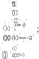
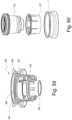
- FIG 32 shows an exploited view of the VBR valve 2 parts with their reference numbers.
- the alternative embodiment of a manual actuator is useful when it is necessary to use the bottles with dispensers not having a probe or to use the bottle without a dispenser.
- Figures 33A and 33B are views of the VBR valve with a manual actuator using the same key mechanism described above and thereby preventing the VBR valve 102 from being removed from the container without knowing the appropriate opening sequence.
- This embodiment also provides the addition of a central actuator hidden within the VBR valve in place of the dispenser probe function.
- Figure 34 shows in a vertical cross-sectional view of the VBR valve the spring 143 pushing the actuator 142 inside the plunger 129 and the O-ring 144 sealing the actuator against plunger 129.
- the components that form part of the security mechanism of a VBR valve with a manual actuator 102 inside the bottle and prevent its disassembly include the bottle collar 1, the position locks 118, the sleeve 114 and its ribs 115, the key box 116 and a locking basket 117.
- Sleeve 114 is the mobile part that moves longitudinally to push the position locks 118 outwards with their ribs 115 when the VBR valve 102 is inside the bottle.
- Figures 35A to 35C show the sleeve 114 with two recesses 145 made on opposite sides of the sleeve 114 body.
- Figure 35A shows an external view of the sleeve 114.
- Figure 35B shows an inner view of channels CE1 and CS1.
- Figure 35C shows a perspective view of the modified sleeve 114.
- Figure 35D shows a detailed cross-sectional view of the recess 145 to show the internal face of the sleeve 114 with certain positions of interest that will be described in the manual actuator operation section in the following paragraphs.
- Figure 35E shows in detail the geometry of the sleeve 114 with its main elements: the anti-rotation septum 122 and the security septum 120, the seal housings 121A and 121B, the ribs 115, the vertical guide 134 and the horizontal guide 125.
- Figures 36A to 36C Modifications done to plunger 129 are shown in Figures 36A to 36C.
- Figure 36A shows a perspective view of plunger 129 with two similar CVE1 channels on opposite sides thereof.
- Figure 36B shows an external view of one side of the plunger 129 to appreciate the geometry of the CVE1 channel.
- Figure 36C shows an internal view of the plunger 129 with the housing AOA1 where the O-ring 144 will be housed to seal the connection between the actuator 142 and the plunger 129.
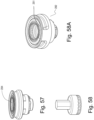
- Figure 36D shows a magnified view of the complete path of each of the two trackers 147 (see Figure 37 ) within each channel CVE1 from an initial position PI1 to a final position PF1, passing through the middle positions PC1 and PE1 when the VBR valve actuator 142 is pressed in sequence and causing the VBR valve actions described below.
- Figure 36E shows the indicator button 139 evidencing that the VBR valve 102 has already been opened.
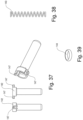
- An actuator 142 with trackers 147 is shown in Figure 37 .
- Figure 38 shows the spring 143 whose function will be to maintain the actuator 142 pressed against the plunger 129.
- Figure 39 shows the O-ring 144 that will seal the connection between the actuator 142 and the plunger 129.
- Figures 40A to 40C are cross-sectional views of the VBR valve 102 with the manual actuator 142 in 3 possible stationary positions:
- Figure 40A shows the VBR valve 102 in the position before being actuated, with its actuator 142 hidden.
- Figure 40B shows the VBR valve when it is operated to expose the actuator 142 outside the VBR valve 102.
- Figure 40C shows the VBR valve 102 open with its actuator 142 hidden.
- FIGS 41A to 41D show the VBR valve 102 is show in a partial vertical cross-sectional view which helps to explain its operation.
- the parts that are seen are the sleeve 114 and the security removal arrangement of the VBR valve.
- actuator 142 is pressed more times to try to open the VBR valve 102 after it has been closed, but this is prevented by the mechanism described in the following paragraphs.
- Figure 41A shows the VBR valve 102 in the closed position with its actuator 142 hidden, where it can be seen that the actuator 142 pushed by spring 143 cannot protrude from the VBR valve because its trackers 147 are resting on the PI point of the plunger 129 CVE channel.
- FIG 41B shows that, when pressed (action represented with arrow AM), the actuator 142 moves into the VBR valve 102, whereupon its trackers 147 move to the PF1 position of the plunger 129 CVE1 channel.
- the design of CVE1 channel forces trackers 147 to move diagonally from point PI1 to point PF1, thereby aligning trackers 147 with the vertical channel of CVE1 channel.
- Figure 41E shows that, when the tracker 147 collides with the slanted wall of the recess 145, slides along it driven by the user's manual pulse on the actuator 142, towards the point PF of the recess 145, where it stops and cannot move further into the VBR valve.
- Figure 42A shows that, due to the geometry of CVE1 channel, point PC1 is misaligned with respect to the vertical channel of CVE1 channel; therefore, when pressing the actuator 142 again, the trackers 147 of the actuator 142 will push the plunger 129 by pressing on the PE1 surface of the CVE1 channel of the plunger 129, transmitting the movement to the plunger 129 in an opening direction ( Figure 42B ) until reaching its maximum opening point.
- Figure 42C shows a perspective interior cross-sectional view of the sleeve 114 inside which the plunger 129 slides and, as mentioned above, the sleeve has a recess 145. The maximum movement limit of the actuator 142 occurs when the trackers 147 reach the PX1 point, after passing through the CS1 channel of recess 145, moving diagonally due the geometry of the recess 145 of sleeve 114.
- Figure 42C shows that CE1 channel allows the tracker 147 to move within it towards the recess 145 and, longitudinally within it, towards point PX1.
- CS1 and CE1 channels are necessary because the sleeve 114 bore is smaller than the diametral distance between trackers the 147. In this way, once trackers 147 reach the recess 145, they appear through it and are trapped by it to guide the actuator 142 with a movement that will be explained below.
- Figure 43A shows the same arrangement as Figure 42C where tracker 147 has reached the maximum PX1 point of the recess 145 of sleeve 114.
- Figure 43B is an enlarged view of recess 145, and shows that to reach point PX1, tracker 147 rests on the slanted wall 149 of recess 145, which causes that when reaching point PX1, tracker 147 is moved horizontally with respect to the CE1 channel of the sleeve 114 moving longitudinally to reach the recess (see Figure 35D ).
- Figures 43C and 43D show that as soon as the user stops pressing on actuator 142, this moves vertically pushed by the spring 143, but tracker 147, being displaced horizontally with respect to the CE1 channel, can no longer return by it, but collides with the slanted wall 150 of recess 145 being directed only from point PX1 to point PR1 of recess 145.
- Figure 43D shows that the tracker is held at point PR1, keeping the actuator 142 hidden, and the actuator this in turn holding the plunger 129 in the open position.
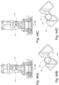
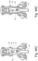
- Figures 44A to 44D show the effect produced by pressing again on the actuator 142, after the tracker 147 has reached the PR1 position. From point PR1, the geometry of the recess 145 of sleeve 114 will force the tracker 147 to move diagonally towards point PY1 of recess 145 ( Figures 44A and 44B ). The effect produced will be a rotation of actuator 142, as shown in the enlarged view of this movement in Figure 44B , which will stop holding plunger 129 after stopping pressure on its surface PE1 (see Figure 42 ).
- plunger 129 pushed by spring 130 will be directed to the closed position, as seen in Figure 44C , and in the enlarged view of Figure 44D (it is partially seen how plunger 129 slides appearing through recess 145). With this last action, VBR valve 102 will remain closed and its actuator 142 hidden inside.
- Figures 46C (plunger 129 hidden) and 46D (showing plunger 129) present the two channels within which both trackers 147 move simultaneously (only one of them is shown).
- Recess 145 of sleeve 114 serves as a retention and path limit function for trackers 147 of actuator 142.
- the CVE1 channel of plunger 129 has the function of allowing the passage of each tracker 147 to move within recess 145 of sleeve 114 and servs as a support point for actuator 142 to keep the VBR valve open by tracker 147 when resting on the PE1 surface of CVE1 channel.
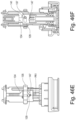
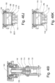
- Figure 46E is a side view of the VBR valve with a manual actuator and Figure 46F shows a longitudinal cross-sectional view of the same.
- Figure 46G shows that the key system necessary to remove the VBR valve is the same as already described for the implementation with an automatic actuator, and that it is based on rotating the key disks 104, 105, 106 according to their manufacturing code so as to align "key" slots 107 through the steps 108 of each disk, and thus allowing sleeve 114 to move when pulled outwards. It is observed that in the embodiment with manual actuator the liquid outlet system is the portion that distinguish it with respect to the embodiment with an automatic actuator.
- Figure 46H shows that the key box 106 has a lid 109 welded to it, where the key box 106 has the function of spacing the disks correctly and isolating them from contact with the environment, thereby preventing the entry of water and hiding the mechanism.
- Figure 46H shows that the manual actuator 142 slides inside the plunger 129 and is held in position by the expansion force of the internal spring 143, which is supported on its rear portion by the spring stop 131.
- This stop 131 is assembled on the sleeve 114 by means of two tabs PT1 in two housings CT1. This means that the force exerted on the actuator 142 is ultimately supported by the sleeve 114.
- Figure 46I shows the abovementioned elements that keep the sleeve 114 in position while the user performs the operations of actuating the button 142.
- Figure 46J shows the sleeve 114 linked to the key box 116 passing inside it, and having axial movements limited inwardly by the base BCV1 of key box 116 that collides with the housing 121A of the O-ring 127 of sleeve 114, and outwardly by key disks 104, 105, and 106 that lock the axial movement of the locking septum 120 of sleeve 114.
- Figure 46L shows that the consequence of the basket 117 being axially locked is that the tapered walls of the key box 116 push the lips L1 of the basket 117 radially outwards, this action causing the lips L1 to interfere at points PBS1 with the bottle collar 1 on the surface 13, and with the locks 118 at point PBI1 preventing the basket 117 from leaving the VBR valve 102.
- Figure 46M shows the VBR valve in a locked position
- Figure 46N shows that there is only one way to unlock this mechanism and allow the VBR valve 102 to be removed from the container.
- the only parts that can be accessed from outside the container are the keys, and more precisely the only thing that can be done is to rotate key disk 104.
- the machine that disassembles the VBR valve 102 has a tool like the one shown in Figure 46P .
- This tool is operated by a machine and acts on the key disk 104 by rotating it to the right and left according to the designated code and with it the two key disks 105 and 106, aligning the slots 107 of the three key disks with the locking septum 120 of sleeve 114, as also described for the VBR valve with an automatic actuator.
- the security VBR valve 102 with a manual actuator comprises a series of cylinders 103 having a single position at which the VBR valve 102 can be removed.
- the process is shown in detail in Figure 46Q as a succession of movements to be carried out by the machine. To ensure the security of the system, the alignment of the slots 107 is not visible from the outside.
- Figure 46S is an exploded view of the VBR valve with a manual actuator 102 presenting on its outer surface a first embodiment of the security code 151 in the form of a barcode that is stored in a computer system, which must be queried to obtain the key that opens the bottle, since this key is inaccessible and encrypted.
- the query is also done by the customer's removing machine, which reads the encrypted key in the barcode or in the two-dimensional QR code by using an optical reader arranged for such purpose and comparing the result with the code database stored on a computer system server arranged for such purpose.
- the opening code may be a two-dimensional code of the QR type.
- the VBR valve without an actuator was designed for drums, that is, bottles, which typically contain 10, 12, or 20 liters of water. However, this valve can also be applied as an alternative embodiment in the typical 200-liter metal sheet oil drums. In the case that the VBR valve requirements are for maximum security regarding the use of the container contents, the possibility of using the security VBR valve as a coded lid is provided. In the different views of Figure 47 , it is shown that the key system is the same as that described above, where the sleeve is replaced by the central part 248 as shown in Figure 47 .
- the components involved in the mechanism securing a VBR valve without an actuator 202 inside the bottle and preventing its disassembly comprise the bottle collar 1, the position locks 218, a central part 248, and its septa 215, the key box 216, and the locking basket 217.
- the central part 248 is the moving portion that runs longitudinally to push the position locks 218 outwards with their septa 215 when the VBR valve 202 is inside the bottle.
- the VBR valve 202 itself must be removed from the bottle to utilize its contents, so that the customer can use the contents of the bottle only when they have an access code, for example, for chemicals, oils, fuels, in which the customer is, for example, a vendor or a factory, but it is not intended for home distribution or administrative offices.
- an access code for example, for chemicals, oils, fuels, in which the customer is, for example, a vendor or a factory, but it is not intended for home distribution or administrative offices.
- the central part 248 fulfills the same function as the sleeve 14 with respect to the key system for its removal. Its peculiarity is that it is a blind part, and its function is to prevent flowing out of the contents of the container.
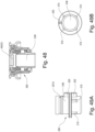
- Figure 48 is a cross-sectional view where the PEXT recess stands out, the function of which being allowing the central part 248 to be taken to remove the VBR valve thereby enabling access to the container contents once the correct keys of the container VBR valve 202 have been entered.
- Figures 49A and 49B are a side and a bottom view of the central part 248. They show that the referenced portions are the same as for sleeve 14, and this allows the central part to fulfill the same functions as the sleeve 14 with respect to the key box, the security lock actuators, and its O-ring system for achieving the system sealing.
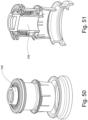
- Figure 50 shows a perspective view of a VBR valve without an actuator.
- Figure 51 shows a perspective longitudinal cross-sectional view of the VBR valve without an actuator.
- Figure 52 shows a bottle with its collar in place and the VBR valve removed from the bottle to access the contents of the container.
- the central part 248 fulfills the function of removing the VBR valve 202 from the bottle collar 1 and thus releasing the liquid from the container. If the VBR valve without an actuator 202 is not removed, the contents of the bottle cannot be accessed.
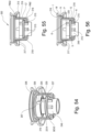
- Figure 54 shows that in the VBR valve without an actuator 202, the central part 248 is connected to the key box 216, passes through it and has axial movements limited inwardly by the base BCV2 of key box 216 which collides with housing 221A of the O-ring 227, and outwardly by the key disks 204, 205, and 206 that lock the axial movement of the central part 248 locking septum 220.
- Figure 55 shows that the key disks 204, 205, and 206 lock the axial movement of the central part 248 to maintain the septa 215 of the central part 248 radially pushing the locks 218 outwards, so that these in turn lock the axial movement of the basket 217 with respect to the key box 16 due to diametral interference at point PBI2.
- the consequence of the basket 217 being locked is that the tapered walls of the key box 216 radially push the lips L2 of the basket 217 outwards, this action causing the lips L2 to move away from the center and axially interfering at point PBS2 with the bottle collar 1 on the surface 213, which prevents the basket 217 from coming out from the VBR valve.
- Figure 57 shows that there is only one way to unlock the VBR valve without an actuator 202 and allow it to be removed from the container.
- only the key disks can be accessed from the container exterior, and more precisely only the key disk 204 can be rotated.
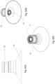
- the way to do it is using a tool like the one shown in Figure 58 .
- This tool is operated by a machine and acts on the key disk 204.
- the machine rotates the key disk 204 to the right and left according to the corresponding code and drags the two key disks 205 and 206 according to the corresponding code by aligning the slots 207 of the three key disks with the septum 220 of the central part 248.
- the slots alignment is not visible from the exterior.
- Figure 58A is a perspective view of a valve without an actuator that shows on its outer surface a first embodiment of the security code 251 in the form of a barcode that is stored in a computer system, which must be queried to obtain the key that opens the bottle since this key is inaccessible and encrypted.
- the query is also done by the customer's removing machine by reading the encrypted key in the barcode or in the two-dimensional QR code using an optical reader arranged for such purpose and comparing the result with the code database stored on a computer system server arranged for such purpose.
- the opening code may be a two-dimensional code of the QR type.
- Figure 61 shows an exploded view of the VBR valve without an actuator 202.
- the basket 217 can be removed together with the rest of the VBR valve without an actuator 202 allows better cleaning of the assembly before refilling the bottle, which is particularly important if it contains a liquid for human consumption, such as drinking water or juice.
- the basket 217 is not an independent part, but is welded to collar 1.
- valve 302 the same security system described in the embodiments of the previous paragraphs is used to prevent the valve from being removed from the bottle, that is, a key box with coded cylinders.
- the difference with the other versions lies in the opening mechanism of the valve 334 for removing the contents of the bottle 301.
- the valve 302 is also intended for use in dispensers that comprise an actuating male or probe 33, which when placing the bottle 1A in position opens the VBR_C valve. o
- Figures 62A to 62C are perspective views of the valve placed in bottle 1A (with only the upper portion represented).
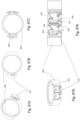
- Figure 62C shows that the key box 16 is the same, and Figure 62B shows the inner portion of the valve 302.
- Figures 62D is a top view
- Figure 62E is a side view
- Figure 62F shows a bottom view of the valve.
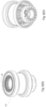
- Figures 62G and 62H show perspective views of the valve where the encrypted opening code is observed.
- Figure 62G is a perspective view of the compact valve that shows on its outer surface a first embodiment of the security code 331 in the form of a barcode that is stored in a computer system, which must be queried to obtain the key that opens the bottle, since this key is inaccessible and encrypted.
- the query is also done by the customer's removing machine, which reads the encrypted key in the barcode or in the two-dimensional QR code using an optical reader arranged for such purpose and comparing the result with the code database stored on a computer system server arranged for such purpose.
- the opening code may be a two-dimensional code of the QR type.
- the valve 302 comprises a sleeve 304, a closing base 305, the closing plug 306, a spring 307 and a security ring 308. Additionally, they show the assembly 333 (of the key system described in previous paragraphs).
- Figures 66A to 66D show the sleeve 304. This part serves as the outlet probe for the bottle's contents.
- Figures 66B and 66C show the portion marked as CL, which fulfills the same functions described with respect to the operation of the key system described on page 23 of this document under the heading " Secure opening of a bottle with an automatic actuator”.
- this sleeve 304 on which the outlet of the bottle will be closed by means of plug 306 is shown.
- the sleeve retainer 309 consisting of a lip with an outer diameter larger than the sleeve 304 diameter, which will serve to limit the movement of the closing base 305 during the operation of the valve.
- Figures 67A to 67E show the closing base 305 composed of a ring containing the following elements: a male hinge 311, a cavity 325 and a labyrinth 313 which will fulfill the function of allowing a single opening of the bottle during use.
- Figure 67E shows labyrinth 313 consisting of two channels, channel A 323 and channel B 324.
- selector 319 When selector 319 is in channel A, it can move downwards exiting the labyrinth 313, and when selector 319 is in channel B, it cannot come out of the channel due to the geometry thereof.
- the channels are duplicated for better security and separate selectors 319 move in each of them.
- FIGs 68A to 68D show plug 306.
- This part is the one that is directly operated by the probe 33 of the dispenser blocking the discharge of the bottle's contents, which occurs when its surface 314 is in contact with the surface 310 of the sleeve 304.
- the plug 306 there is also a female hinge 315 which will serve to provide the opening rotation movement with respect to the closing base 305 when engage d on the male hinge 311 (see Figures 67A and B ).
- the indicator 316 can also be observed, which will allow the status of the valve to be known by appearing through the indicator window 318 of the security ring 308 (see Figure 69B ).
- the plug retainer 317 is seen, consisting of tabs that will serve to limit the movement of the labyrinth by interacting with the labyrinth retainer 320.
- FIGs 69A to 69D show the security ring 308, in which the labyrinth retainer 320 can be seen, which, when mounted in its position on the plug 306, will have its movement restricted by the plug retainer 317 (see Figures 68A and 68B ), being able to perform rotation movements only about the axis of the plug 306. They also show the indicator window 318 through which the status of the security valve may be controlled since the indicator 316 comes out through this window, this indicator also limiting the rotation movement of the security ring 308, so that the selectors 319 will move between portions A and B of the labyrinth 313.
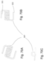
- Figures 70A to 70C show the spring 307 whose function is to return the plug 306 to its position once the bottle is removed from the dispenser.
- the spring is housed in the cavity 325 of the closing base 305 (see Figure 73A ) and its ends 321, 322 force the closure of the plug 306 with one of its ends 321, while the other end 322 rests on the closing base 305.
- Figures 71A to 71D show the coupling between the sleeve 304 and the closing base 305.
- Figure 71A shows the two parts to be mounted, the sleeve 304 and the closing base 305.
- Figure 71B is a cross-sectional view of these parts showing the retainers 309 and 312 of both parts.
- the outer diameter of the retainer 309 is larger than the bore of the retainer 312.
- Figure 71C shows the two assembled parts
- Figure 71D is a cross-sectional view of the parts in the assembled position.
- Figures 72A to 72D show the assembly of the plug 306 on the closure base 305.
- the mounting operation is carried out by forcing the male hinge 315 of the plug 305 into the female hinge 311 of the closing base 305, whereby the closing plug 306 has a rotation limitation on the hinge formed by the male 315 and the female 311.
- Figure 72A and 72B show the parts to be assembled from two points of view.
- Figure 72C is a cross-sectional view of the assembled parts; and
- Figure 72D shows the opening movement of the plug 306 on the base 305.
- Figures 73A and 72B show the assembly of the spring 307 in the cavity 325 of the closing base 305, the end 322 passing through the slot 326 of the plug 306 and the end 321 pressing on the outer wall of the closing base 305.
- Figures 74A to 74D show the assembly of the security ring 308 on the closing plug 306.
- Figure 74A shows the components to be assembled
- Figure 74B shows the retainer 312 of plug 306 and the retainer 320 of security ring 308. Assembly occurs by forcing the retainer 312 of plug 306 to pass through the retainer 320 of security ring 308, which results in the passing of the indicator 316 of the plug 306 through the indicator window 318.
- the security ring 308 is positioned on the plug 306, without axial movement on the closing plug 306, but with the possibility of rotating on the closing plug 306 an angle allowed by the indicator 316 moving within the indicator window 318.
- the closing mechanism is assembled.
- Figures 75A to 75C are a cross-sectional view of the operation of the opening section 334.
- Figure 75A shows the closed position of the valve when leaving the bottling plant. Note that closing of the valve is produced by means of the contact between the surface 310 of the sleeve 304 and the surface 314 of the plug 306. For this contact to occur, the closing base 305 is moved upwards. During this operation the closing base 305 is pushed by the closing plug 306 until the plug 306 abuts the sleeve 304.
- Figures 75B and 75C show what happens when the closing plug 306 is pushed to open the VBR_C valve.
- the plug 306 moves axially, since its wall 314 moves along the wall 310 of the sleeve because the only thing that retains the plug 306 in its position inside the sleeve 304 is the friction between both, when the plug 306 moves, it will also move the closing base 305 until its retention 312 stops on the retention 309 of the sleeve 304.
- the closing plug 306 continues its movement, but now it rotates on the hinge formed between the closing base 305 and the closing plug 306, thereby opening the discharge of the bottle contents through the valve.
- the security ring 308 is depicted as transparent to visualize the operation of the labyrinth trackers 319 within the labyrinth 313.
- Figure 76 B to Figure 77 show an enlarged view of this portion to visualize the operation of the labyrinth trackers 319 within the labyrinth 313.
- Figures 76 C to 76E also show the operation of the security ring 308.
- Figure 76 C shows its position when leaving the factory, that is, with the labyrinth selectors 319 of the security ring 308 in separate channels A 323 of the closing base 305 labyrinth 313.
- Figure 76 D also shows what happens when the plug 306 stars the rotation movement during the opening action.
- Locking ring 308 is attached to plug 306 (see assembly).
- the labyrinth selectors 319 must necessarily be caused to exit the labyrinth 313 of the closing base 305, and due to the geometry of the labyrinth 313 (see Figure 70E) this exit can only be carried out if the labyrinth trackers 319 are in channels A 323 of labyrinth 313.
- Figure 76 F shows the final position of the plug 306 completely open, with the selectors 319 of the part 308 outside the labyrinth 313 of part 305.
- Figure 76 G shows what happens when the plug 306 is closed.
- the labyrinth selectors 319 of the security ring 308 will enter the labyrinth 313 of the closing base 305 through the window 320 and upon reaching the wall 328 of the labyrinth 313 they will cause the labyrinth selectors 319 to rotate the security ring 308, whereby the trackers 319 will now be located on channel B 324, as represented in Figure 76 H.
- Figure 77 shows that the labyrinth trackers 319 of the security ring 308, when located in channel B 324 of the labyrinth 313 of part 305, can no longer leave this channel B 324 due to the geometry of the stop 329 of the labyrinth 313, thereby preventing the valve from being opened for a second time.
- Figures 78A and 78B show the result of the security ring 308 rotation.
- Figure 78A shows that the indicator 316 is visible by the indicator window 318, evidencing that the valve has not been used.
- Figure 78B the indicator is not visible in the indicator window 318 indicating that the VBR_C valve has already been used and cannot be opened.
- the entire mechanism can be reset only by removing the VBR_C valve from the bottle, repositioning the plug 306 to its fully closed position and placing the security ring in the "ready for use” position, that is, with the labyrinth trackers in the channel A 323.
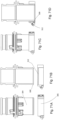
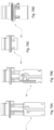
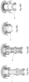
- Figures 79A to 79D show side views of the four embodiments of the VBR valve: on the left the VBR valve with an automatic actuator 2, on the middle-left the VBR valve with a manual actuator 102, on the middle-right the VBR valve without an actuator 202, and on the right the compact VBR_C valve 302.
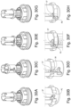
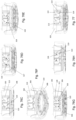
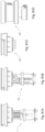
- Figures 80A to 80D show perspective cross-sectional views of the four embodiments of the VBR valve: on the left the VBR valve with an automatic actuator 2, on the middle-left the VBR valve with a manual actuator 102, on the middle-right the VBR valve without an actuator 202, and on the right the compact VBR_C valve 302.
- Figures 81A to 81D show complete side views of the four embodiments of the VBR valve: on the left the VBR valve with an automatic actuator 2, on the middle-left the VBR valve with a manual actuator 102, on the middle-right the VBR valve without an actuator 202, and on the right the compact VBR_C valve 302.
- Figures 82A - 82D show complete perspective cross-sectional views of the four embodiments of the VBR valve with an automatic actuator 2 on the left, with manual actuator 102 on the middle - left, the valve without an actuator 202 on the middle - right, and the compact VBR_C valve 302 on the right.
Landscapes
- Engineering & Computer Science (AREA)
- Mechanical Engineering (AREA)
- General Engineering & Computer Science (AREA)
- Closures For Containers (AREA)
- Lift Valve (AREA)
Applications Claiming Priority (1)
| Application Number | Priority Date | Filing Date | Title |
|---|---|---|---|
| UY0001040036A UY40036A (es) | 2022-11-22 | 2022-11-22 | Válvula de seguridad para botellón retornable, collar de botellón y proceso para taponar un |
Publications (2)
| Publication Number | Publication Date |
|---|---|
| EP4414286A2 true EP4414286A2 (de) | 2024-08-14 |
| EP4414286A3 EP4414286A3 (de) | 2024-09-25 |
Family
ID=89122031
Family Applications (1)
| Application Number | Title | Priority Date | Filing Date |
|---|---|---|---|
| EP23211470.2A Pending EP4414286A3 (de) | 2022-11-22 | 2023-11-22 | Sicherheitsventil für mehrwegflasche, flaschenmanschette und verfahren zum verschliessen einer mehrwegflasche |
Country Status (5)
| Country | Link |
|---|---|
| US (1) | US12460741B2 (de) |
| EP (1) | EP4414286A3 (de) |
| AR (1) | AR131067A1 (de) |
| MX (1) | MX2023013843A (de) |
| UY (1) | UY40036A (de) |
Cited By (1)
| Publication number | Priority date | Publication date | Assignee | Title |
|---|---|---|---|---|
| US20250012375A1 (en) * | 2022-11-22 | 2025-01-09 | Sides R&D Uruguay S.A. | Safety valve for returnable bottle, bottle collar and process for closing a returnable bottle |
Citations (5)
| Publication number | Priority date | Publication date | Assignee | Title |
|---|---|---|---|---|
| EP0706952A1 (de) | 1994-09-13 | 1996-04-17 | Grupo Stevi S.A. de C.V. | Garantieverschluss zum Verhindern des Wiederfüllens von Behältern |
| GB2329892A (en) | 1997-10-01 | 1999-04-07 | Rical Sa | Closure with tamper evident portion |
| GB2366287A (en) | 2000-08-31 | 2002-03-06 | Montgomery Daniel & Son Ltd | A tamper-evident anti-refill closure |
| AR056057A1 (es) | 2005-12-12 | 2007-09-19 | Fuentes Esparza Juan Manuel | Tapa inviolable y descartable de una sola pieza, sin junta ni guarnicion para botellones de agua retornables |
| EP2925666B1 (de) | 2012-12-03 | 2016-09-28 | BERICAP Holding GmbH | Behälterverschluss für überkopfentleerung |
Family Cites Families (4)
| Publication number | Priority date | Publication date | Assignee | Title |
|---|---|---|---|---|
| US7950550B2 (en) * | 2004-05-06 | 2011-05-31 | Diversey, Inc. | Metering and dispensing closure |
| CN102152891A (zh) * | 2011-04-01 | 2011-08-17 | 龚道宽 | 防伪密码锁瓶盖 |
| BE1027022B1 (nl) * | 2020-03-20 | 2021-06-14 | Altachem | Grensvlakring |
| UY40036A (es) * | 2022-11-22 | 2024-05-15 | Sides R&D Uruguay S A | Válvula de seguridad para botellón retornable, collar de botellón y proceso para taponar un |
-
2022
- 2022-11-22 UY UY0001040036A patent/UY40036A/es unknown
-
2023
- 2023-11-15 AR ARP230103072A patent/AR131067A1/es unknown
- 2023-11-21 US US18/515,519 patent/US12460741B2/en active Active
- 2023-11-21 MX MX2023013843A patent/MX2023013843A/es unknown
- 2023-11-22 EP EP23211470.2A patent/EP4414286A3/de active Pending
Patent Citations (5)
| Publication number | Priority date | Publication date | Assignee | Title |
|---|---|---|---|---|
| EP0706952A1 (de) | 1994-09-13 | 1996-04-17 | Grupo Stevi S.A. de C.V. | Garantieverschluss zum Verhindern des Wiederfüllens von Behältern |
| GB2329892A (en) | 1997-10-01 | 1999-04-07 | Rical Sa | Closure with tamper evident portion |
| GB2366287A (en) | 2000-08-31 | 2002-03-06 | Montgomery Daniel & Son Ltd | A tamper-evident anti-refill closure |
| AR056057A1 (es) | 2005-12-12 | 2007-09-19 | Fuentes Esparza Juan Manuel | Tapa inviolable y descartable de una sola pieza, sin junta ni guarnicion para botellones de agua retornables |
| EP2925666B1 (de) | 2012-12-03 | 2016-09-28 | BERICAP Holding GmbH | Behälterverschluss für überkopfentleerung |
Cited By (2)
| Publication number | Priority date | Publication date | Assignee | Title |
|---|---|---|---|---|
| US20250012375A1 (en) * | 2022-11-22 | 2025-01-09 | Sides R&D Uruguay S.A. | Safety valve for returnable bottle, bottle collar and process for closing a returnable bottle |
| US12460741B2 (en) * | 2022-11-22 | 2025-11-04 | Sides R&D Uruguay S.A. | Safety valve for returnable bottle, bottle collar and process for plugging a returnable bottle |
Also Published As
| Publication number | Publication date |
|---|---|
| US20250012375A1 (en) | 2025-01-09 |
| UY40036A (es) | 2024-05-15 |
| MX2023013843A (es) | 2024-05-23 |
| AR131067A1 (es) | 2025-02-12 |
| EP4414286A3 (de) | 2024-09-25 |
| US12460741B2 (en) | 2025-11-04 |
Similar Documents
| Publication | Publication Date | Title |
|---|---|---|
| EP1102710B1 (de) | Antibetrugsverschluss | |
| US6971552B2 (en) | Aerosol dispenser | |
| JP4464025B2 (ja) | 重力供給流体分与弁 | |
| US5255713A (en) | Valve with integral plastic spring for poppet | |
| EP4414286A2 (de) | Sicherheitsventil für mehrwegflasche, flaschenmanschette und verfahren zum verschliessen einer mehrwegflasche | |
| AU724099B2 (en) | Liquid distribution valve | |
| WO1992004129A2 (en) | Fluid dispensing unit retainer | |
| AU2002303266B2 (en) | Corrosive resistant liquid extraction apparatus | |
| EP1968883B1 (de) | Verriegelungsvorrichtung und -verfahren | |
| KR101070559B1 (ko) | 액체 저장용기 마개 조립체 | |
| WO1998010996A1 (en) | Actuator assembly to prevent inadvertent product discharge upon installation on stem | |
| US7434707B2 (en) | Childproof attachment for a dispenser | |
| EP1950144B1 (de) | Verschluss | |
| GB2219570A (en) | Non-refillable closures for containers | |
| KR20120027261A (ko) | 액체 용기용 탬퍼-프루프 삽입부 | |
| CA2418603A1 (en) | Oil field sample apparatus | |
| EP0706952A1 (de) | Garantieverschluss zum Verhindern des Wiederfüllens von Behältern | |
| US11958737B2 (en) | Dispensing tap for rigid and flexible containers, preferably of the bag-in-box type | |
| US8616420B2 (en) | Bottle closure with breakaway skirt for non-refillable bottles | |
| EP3625139B1 (de) | Flüssigkeitsbehälter; ausgestattet mit ausgabestopfen mit integriertem luftkanal und garantiesiegel mit automatischer öffnung | |
| US20220002136A1 (en) | Self venting valve closure | |
| RU2792963C2 (ru) | Раздаточная головка, система раздачи напитков, способы активации и дезактивации раздаточной головки | |
| US3073469A (en) | Non-refillable closure devices for bottles | |
| EP4624361A1 (de) | Verschlussvorrichtung für behälter | |
| US317561A (en) | John ernest minnitt and john henry vickees |
Legal Events
| Date | Code | Title | Description |
|---|---|---|---|
| PUAI | Public reference made under article 153(3) epc to a published international application that has entered the european phase |
Free format text: ORIGINAL CODE: 0009012 |
|
| STAA | Information on the status of an ep patent application or granted ep patent |
Free format text: STATUS: THE APPLICATION HAS BEEN PUBLISHED |
|
| AK | Designated contracting states |
Kind code of ref document: A2 Designated state(s): AL AT BE BG CH CY CZ DE DK EE ES FI FR GB GR HR HU IE IS IT LI LT LU LV MC ME MK MT NL NO PL PT RO RS SE SI SK SM TR |
|
| PUAL | Search report despatched |
Free format text: ORIGINAL CODE: 0009013 |
|
| AK | Designated contracting states |
Kind code of ref document: A3 Designated state(s): AL AT BE BG CH CY CZ DE DK EE ES FI FR GB GR HR HU IE IS IT LI LT LU LV MC ME MK MT NL NO PL PT RO RS SE SI SK SM TR |
|
| RIC1 | Information provided on ipc code assigned before grant |
Ipc: B67D 3/02 20060101ALI20240817BHEP Ipc: B65D 50/06 20060101ALI20240817BHEP Ipc: B65D 49/00 20060101ALI20240817BHEP Ipc: B65D 47/24 20060101AFI20240817BHEP |
|
| STAA | Information on the status of an ep patent application or granted ep patent |
Free format text: STATUS: REQUEST FOR EXAMINATION WAS MADE |
|
| 17P | Request for examination filed |
Effective date: 20250210 |
|
| STAA | Information on the status of an ep patent application or granted ep patent |
Free format text: STATUS: EXAMINATION IS IN PROGRESS |
|
| 17Q | First examination report despatched |
Effective date: 20250717 |