EP4414321A2 - Appareil et procédé pour fournir de l'eau de refroidissement pour la production d'ammoniac et/ou d'hydrogène - Google Patents
Appareil et procédé pour fournir de l'eau de refroidissement pour la production d'ammoniac et/ou d'hydrogène Download PDFInfo
- Publication number
- EP4414321A2 EP4414321A2 EP23217998.6A EP23217998A EP4414321A2 EP 4414321 A2 EP4414321 A2 EP 4414321A2 EP 23217998 A EP23217998 A EP 23217998A EP 4414321 A2 EP4414321 A2 EP 4414321A2
- Authority
- EP
- European Patent Office
- Prior art keywords
- cooling
- hydrogen
- plant
- water
- ammonia
- Prior art date
- Legal status (The legal status is an assumption and is not a legal conclusion. Google has not performed a legal analysis and makes no representation as to the accuracy of the status listed.)
- Pending
Links
Images

Classifications
-
- C—CHEMISTRY; METALLURGY
- C25—ELECTROLYTIC OR ELECTROPHORETIC PROCESSES; APPARATUS THEREFOR
- C25B—ELECTROLYTIC OR ELECTROPHORETIC PROCESSES FOR THE PRODUCTION OF COMPOUNDS OR NON-METALS; APPARATUS THEREFOR
- C25B9/00—Cells or assemblies of cells; Constructional parts of cells; Assemblies of constructional parts, e.g. electrode-diaphragm assemblies; Process-related cell features
- C25B9/60—Constructional parts of cells
- C25B9/67—Heating or cooling means
-
- C—CHEMISTRY; METALLURGY
- C01—INORGANIC CHEMISTRY
- C01C—AMMONIA; CYANOGEN; COMPOUNDS THEREOF
- C01C1/00—Ammonia; Compounds thereof
- C01C1/02—Preparation, purification or separation of ammonia
- C01C1/04—Preparation of ammonia by synthesis
- C01C1/0405—Preparation of ammonia by synthesis from N2 and H2 in presence of a catalyst
- C01C1/0447—Apparatus other than synthesis reactors
-
- B—PERFORMING OPERATIONS; TRANSPORTING
- B01—PHYSICAL OR CHEMICAL PROCESSES OR APPARATUS IN GENERAL
- B01J—CHEMICAL OR PHYSICAL PROCESSES, e.g. CATALYSIS OR COLLOID CHEMISTRY; THEIR RELEVANT APPARATUS
- B01J19/00—Chemical, physical or physico-chemical processes in general; Their relevant apparatus
-
- B—PERFORMING OPERATIONS; TRANSPORTING
- B01—PHYSICAL OR CHEMICAL PROCESSES OR APPARATUS IN GENERAL
- B01J—CHEMICAL OR PHYSICAL PROCESSES, e.g. CATALYSIS OR COLLOID CHEMISTRY; THEIR RELEVANT APPARATUS
- B01J19/00—Chemical, physical or physico-chemical processes in general; Their relevant apparatus
- B01J19/0006—Controlling or regulating processes
- B01J19/0013—Controlling the temperature of the process
-
- B—PERFORMING OPERATIONS; TRANSPORTING
- B01—PHYSICAL OR CHEMICAL PROCESSES OR APPARATUS IN GENERAL
- B01J—CHEMICAL OR PHYSICAL PROCESSES, e.g. CATALYSIS OR COLLOID CHEMISTRY; THEIR RELEVANT APPARATUS
- B01J19/00—Chemical, physical or physico-chemical processes in general; Their relevant apparatus
- B01J19/24—Stationary reactors without moving elements inside
- B01J19/245—Stationary reactors without moving elements inside placed in series
-
- C—CHEMISTRY; METALLURGY
- C01—INORGANIC CHEMISTRY
- C01B—NON-METALLIC ELEMENTS; COMPOUNDS THEREOF; METALLOIDS OR COMPOUNDS THEREOF NOT COVERED BY SUBCLASS C01C
- C01B21/00—Nitrogen; Compounds thereof
- C01B21/04—Purification or separation of nitrogen
- C01B21/0405—Purification or separation processes
- C01B21/0433—Physical processing only
-
- C—CHEMISTRY; METALLURGY
- C01—INORGANIC CHEMISTRY
- C01B—NON-METALLIC ELEMENTS; COMPOUNDS THEREOF; METALLOIDS OR COMPOUNDS THEREOF NOT COVERED BY SUBCLASS C01C
- C01B3/00—Hydrogen; Gaseous mixtures containing hydrogen; Separation of hydrogen from mixtures containing it; Purification of hydrogen; Reversible storage of hydrogen
- C01B3/02—Production of hydrogen; Production of gaseous mixtures containing hydrogen
-
- C—CHEMISTRY; METALLURGY
- C01—INORGANIC CHEMISTRY
- C01C—AMMONIA; CYANOGEN; COMPOUNDS THEREOF
- C01C1/00—Ammonia; Compounds thereof
- C01C1/02—Preparation, purification or separation of ammonia
- C01C1/04—Preparation of ammonia by synthesis
- C01C1/0405—Preparation of ammonia by synthesis from N2 and H2 in presence of a catalyst
-
- C—CHEMISTRY; METALLURGY
- C01—INORGANIC CHEMISTRY
- C01C—AMMONIA; CYANOGEN; COMPOUNDS THEREOF
- C01C1/00—Ammonia; Compounds thereof
- C01C1/02—Preparation, purification or separation of ammonia
- C01C1/04—Preparation of ammonia by synthesis
- C01C1/0405—Preparation of ammonia by synthesis from N2 and H2 in presence of a catalyst
- C01C1/0417—Preparation of ammonia by synthesis from N2 and H2 in presence of a catalyst characterised by the synthesis reactor, e.g. arrangement of catalyst beds and heat exchangers in the reactor
-
- C—CHEMISTRY; METALLURGY
- C01—INORGANIC CHEMISTRY
- C01C—AMMONIA; CYANOGEN; COMPOUNDS THEREOF
- C01C1/00—Ammonia; Compounds thereof
- C01C1/02—Preparation, purification or separation of ammonia
- C01C1/04—Preparation of ammonia by synthesis
- C01C1/0405—Preparation of ammonia by synthesis from N2 and H2 in presence of a catalyst
- C01C1/0447—Apparatus other than synthesis reactors
- C01C1/0452—Heat exchangers
-
- C—CHEMISTRY; METALLURGY
- C01—INORGANIC CHEMISTRY
- C01C—AMMONIA; CYANOGEN; COMPOUNDS THEREOF
- C01C1/00—Ammonia; Compounds thereof
- C01C1/02—Preparation, purification or separation of ammonia
- C01C1/04—Preparation of ammonia by synthesis
- C01C1/0405—Preparation of ammonia by synthesis from N2 and H2 in presence of a catalyst
- C01C1/0482—Process control; Start-up or cooling-down procedures
-
- C—CHEMISTRY; METALLURGY
- C01—INORGANIC CHEMISTRY
- C01C—AMMONIA; CYANOGEN; COMPOUNDS THEREOF
- C01C1/00—Ammonia; Compounds thereof
- C01C1/02—Preparation, purification or separation of ammonia
- C01C1/04—Preparation of ammonia by synthesis
- C01C1/0405—Preparation of ammonia by synthesis from N2 and H2 in presence of a catalyst
- C01C1/0488—Processes integrated with preparations of other compounds, e.g. methanol, urea or with processes for power generation
-
- C—CHEMISTRY; METALLURGY
- C25—ELECTROLYTIC OR ELECTROPHORETIC PROCESSES; APPARATUS THEREFOR
- C25B—ELECTROLYTIC OR ELECTROPHORETIC PROCESSES FOR THE PRODUCTION OF COMPOUNDS OR NON-METALS; APPARATUS THEREFOR
- C25B1/00—Electrolytic production of inorganic compounds or non-metals
- C25B1/01—Products
- C25B1/02—Hydrogen or oxygen
- C25B1/04—Hydrogen or oxygen by electrolysis of water
-
- C—CHEMISTRY; METALLURGY
- C25—ELECTROLYTIC OR ELECTROPHORETIC PROCESSES; APPARATUS THEREFOR
- C25B—ELECTROLYTIC OR ELECTROPHORETIC PROCESSES FOR THE PRODUCTION OF COMPOUNDS OR NON-METALS; APPARATUS THEREFOR
- C25B15/00—Operating or servicing cells
- C25B15/02—Process control or regulation
- C25B15/021—Process control or regulation of heating or cooling
-
- C—CHEMISTRY; METALLURGY
- C25—ELECTROLYTIC OR ELECTROPHORETIC PROCESSES; APPARATUS THEREFOR
- C25B—ELECTROLYTIC OR ELECTROPHORETIC PROCESSES FOR THE PRODUCTION OF COMPOUNDS OR NON-METALS; APPARATUS THEREFOR
- C25B9/00—Cells or assemblies of cells; Constructional parts of cells; Assemblies of constructional parts, e.g. electrode-diaphragm assemblies; Process-related cell features
- C25B9/60—Constructional parts of cells
- C25B9/65—Means for supplying current; Electrode connections; Electric inter-cell connections
-
- C—CHEMISTRY; METALLURGY
- C25—ELECTROLYTIC OR ELECTROPHORETIC PROCESSES; APPARATUS THEREFOR
- C25B—ELECTROLYTIC OR ELECTROPHORETIC PROCESSES FOR THE PRODUCTION OF COMPOUNDS OR NON-METALS; APPARATUS THEREFOR
- C25B9/00—Cells or assemblies of cells; Constructional parts of cells; Assemblies of constructional parts, e.g. electrode-diaphragm assemblies; Process-related cell features
- C25B9/70—Assemblies comprising two or more cells
-
- F—MECHANICAL ENGINEERING; LIGHTING; HEATING; WEAPONS; BLASTING
- F25—REFRIGERATION OR COOLING; COMBINED HEATING AND REFRIGERATION SYSTEMS; HEAT PUMP SYSTEMS; MANUFACTURE OR STORAGE OF ICE; LIQUEFACTION SOLIDIFICATION OF GASES
- F25D—REFRIGERATORS; COLD ROOMS; ICE-BOXES; COOLING OR FREEZING APPARATUS NOT OTHERWISE PROVIDED FOR
- F25D31/00—Other cooling or freezing apparatus
-
- F—MECHANICAL ENGINEERING; LIGHTING; HEATING; WEAPONS; BLASTING
- F28—HEAT EXCHANGE IN GENERAL
- F28F—DETAILS OF HEAT-EXCHANGE AND HEAT-TRANSFER APPARATUS, OF GENERAL APPLICATION
- F28F27/00—Control arrangements or safety devices specially adapted for heat-exchange or heat-transfer apparatus
- F28F27/003—Control arrangements or safety devices specially adapted for heat-exchange or heat-transfer apparatus specially adapted for cooling towers
-
- B—PERFORMING OPERATIONS; TRANSPORTING
- B01—PHYSICAL OR CHEMICAL PROCESSES OR APPARATUS IN GENERAL
- B01J—CHEMICAL OR PHYSICAL PROCESSES, e.g. CATALYSIS OR COLLOID CHEMISTRY; THEIR RELEVANT APPARATUS
- B01J2219/00—Chemical, physical or physico-chemical processes in general; Their relevant apparatus
- B01J2219/00002—Chemical plants
- B01J2219/00004—Scale aspects
- B01J2219/00006—Large-scale industrial plants
-
- B—PERFORMING OPERATIONS; TRANSPORTING
- B01—PHYSICAL OR CHEMICAL PROCESSES OR APPARATUS IN GENERAL
- B01J—CHEMICAL OR PHYSICAL PROCESSES, e.g. CATALYSIS OR COLLOID CHEMISTRY; THEIR RELEVANT APPARATUS
- B01J2219/00—Chemical, physical or physico-chemical processes in general; Their relevant apparatus
- B01J2219/00002—Chemical plants
- B01J2219/00027—Process aspects
- B01J2219/0004—Processes in series
-
- B—PERFORMING OPERATIONS; TRANSPORTING
- B01—PHYSICAL OR CHEMICAL PROCESSES OR APPARATUS IN GENERAL
- B01J—CHEMICAL OR PHYSICAL PROCESSES, e.g. CATALYSIS OR COLLOID CHEMISTRY; THEIR RELEVANT APPARATUS
- B01J2219/00—Chemical, physical or physico-chemical processes in general; Their relevant apparatus
- B01J2219/00049—Controlling or regulating processes
- B01J2219/00051—Controlling the temperature
- B01J2219/00054—Controlling or regulating the heat exchange system
-
- B—PERFORMING OPERATIONS; TRANSPORTING
- B01—PHYSICAL OR CHEMICAL PROCESSES OR APPARATUS IN GENERAL
- B01J—CHEMICAL OR PHYSICAL PROCESSES, e.g. CATALYSIS OR COLLOID CHEMISTRY; THEIR RELEVANT APPARATUS
- B01J2219/00—Chemical, physical or physico-chemical processes in general; Their relevant apparatus
- B01J2219/00049—Controlling or regulating processes
- B01J2219/00051—Controlling the temperature
- B01J2219/00074—Controlling the temperature by indirect heating or cooling employing heat exchange fluids
- B01J2219/00087—Controlling the temperature by indirect heating or cooling employing heat exchange fluids with heat exchange elements outside the reactor
- B01J2219/00103—Controlling the temperature by indirect heating or cooling employing heat exchange fluids with heat exchange elements outside the reactor in a heat exchanger separate from the reactor
-
- B—PERFORMING OPERATIONS; TRANSPORTING
- B01—PHYSICAL OR CHEMICAL PROCESSES OR APPARATUS IN GENERAL
- B01J—CHEMICAL OR PHYSICAL PROCESSES, e.g. CATALYSIS OR COLLOID CHEMISTRY; THEIR RELEVANT APPARATUS
- B01J2219/00—Chemical, physical or physico-chemical processes in general; Their relevant apparatus
- B01J2219/00049—Controlling or regulating processes
- B01J2219/00051—Controlling the temperature
- B01J2219/00159—Controlling the temperature controlling multiple zones along the direction of flow, e.g. pre-heating and after-cooling
-
- C—CHEMISTRY; METALLURGY
- C01—INORGANIC CHEMISTRY
- C01B—NON-METALLIC ELEMENTS; COMPOUNDS THEREOF; METALLOIDS OR COMPOUNDS THEREOF NOT COVERED BY SUBCLASS C01C
- C01B2203/00—Integrated processes for the production of hydrogen or synthesis gas
- C01B2203/08—Methods of heating or cooling
- C01B2203/0872—Methods of cooling
- C01B2203/0883—Methods of cooling by indirect heat exchange
-
- C—CHEMISTRY; METALLURGY
- C25—ELECTROLYTIC OR ELECTROPHORETIC PROCESSES; APPARATUS THEREFOR
- C25B—ELECTROLYTIC OR ELECTROPHORETIC PROCESSES FOR THE PRODUCTION OF COMPOUNDS OR NON-METALS; APPARATUS THEREFOR
- C25B1/00—Electrolytic production of inorganic compounds or non-metals
- C25B1/01—Products
- C25B1/27—Ammonia
-
- Y—GENERAL TAGGING OF NEW TECHNOLOGICAL DEVELOPMENTS; GENERAL TAGGING OF CROSS-SECTIONAL TECHNOLOGIES SPANNING OVER SEVERAL SECTIONS OF THE IPC; TECHNICAL SUBJECTS COVERED BY FORMER USPC CROSS-REFERENCE ART COLLECTIONS [XRACs] AND DIGESTS
- Y02—TECHNOLOGIES OR APPLICATIONS FOR MITIGATION OR ADAPTATION AGAINST CLIMATE CHANGE
- Y02E—REDUCTION OF GREENHOUSE GAS [GHG] EMISSIONS, RELATED TO ENERGY GENERATION, TRANSMISSION OR DISTRIBUTION
- Y02E60/00—Enabling technologies; Technologies with a potential or indirect contribution to GHG emissions mitigation
- Y02E60/30—Hydrogen technology
- Y02E60/36—Hydrogen production from non-carbon containing sources, e.g. by water electrolysis
Definitions
- the present innovation relates to providing cooling water for use as a cooling medium for different elements (e.g., heat exchangers etc.) utilized to provide cooling for ammonia manufacturing and/or hydrogen manufacturing.
- Some embodiments can be utilized in conjunction with green hydrogen and/or green ammonia production that may utilize renewable power sources for production of hydrogen and ammonia.
- Green ammonia manufacturing can be provided so that ammonia is made by use of electricity from renewable power sources (e.g., solar power, wind power, hydro-electric power, etc.).
- renewable power sources e.g., solar power, wind power, hydro-electric power, etc.
- Examples of ammonia production that can be provided from renewable power source can also be appreciated from EP3957772A1 and WO2021/089276 and WO2022/089820 , for example.
- Hydrogen production can be provided by use of one or more electrolyzers.
- An example of a system for production of hydrogen can be appreciated from US2022/0290309 .
- embodiments of an apparatus and embodiments of a process that can be adapted for providing cooling water for ammonia production and/or hydrogen production that can be adapted to provide improved operational flexibility as well as lower capital costs and improved safety and maintenance features for installation and operation. Further, some embodiments can provide a reduction in operational costs associated with cooling water use and can also provide an enhanced ecological impact associated with operation.
- embodiments can be particularly beneficial for green ammonia and green hydrogen production facilities or green ammonia production facilities that may include ammonia manufacturing that forms ammonia (NH3 or NH 3 ) from hydrogen (H2 or H 2 ) provided by a hydrogen plant and nitrogen (N2 or N 2 ) provided by an air separation unit (ASU).
- the ASU can be a standalone unit or can be a unit that is included in the hydrogen plant to facilitate hydrogen production and nitrogen production to feed hydrogen and nitrogen to an ammonia production plant.
- Embodiments can also be configured and positioned for plants that can produce hydrogen, green hydrogen, or provide liquid hydrogen production (e.g., produce hydrogen for a hydrogen pipeline supply, etc.).
- an apparatus for providing cooling water for ammonia manufacturing and hydrogen manufacturing can include a first cooling tower that can provide cooling water at a first temperature and a second cooling tower that can provide cooling water at a second temperature that is higher than the first temperature.
- the cooling water fed to these cooling towers can include sea water (e.g., pre-treated sea water, sea water treated via reverse osmosis and/or nanofiltration, etc.).
- the first cooling tower can provide a first stream of the cooling water at the first temperature to one or more heat exchangers as a cooling medium for cooling one or more streams for an ammonia manufacturing plant and also one or more streams for a hydrogen production plant.
- the first stream can be split so that a first portion of the first stream of cooling water is fed to a first heat exchanger to provide cooling for ammonia manufacturing and a second portion of the first stream of cooling water is fed to a second heat exchanger to provide cooling for hydrogen production.
- the second cooling tower can output a second stream of cooling water at the second temperature to feed to a third heat exchanger to provide cooling of one or more flows received from gas coolers and/or electrolyte coolers of the hydrogen production plant.
- the second temperature of the cooling water output from the second cooling tower can be up to 10°C higher than the first temperature or can be another suitable temperature that is higher than the first temperature of the cooling water output from the first cooling tower.
- the second temperature can be greater than 0.5°C higher than the first temperature and less than or equal to 10°C higher than the first temperature, can be between 0.5°C and 7°C ( i.e., in a range from 0.5°C to 7°C) higher than the first temperature, can be between 1°C and 10°C ( i.e., in a range from 1°C to 10°C) higher than the first temperature or be another suitable temperature that is greater than the first temperature of the cooling water output by the first cooling tower.
- the second temperature can be more than 10°C higher than the first temperature as well, e.g., between 2°C and 20°C ( i.e., in a range from 2°C to 20°C) higher, between 5°C and 15°C ( i.e., in a range from 5°C to 15°C) higher, greater than 1°C higher and less than or equal to 25°C higher etc.).
- the hydrogen plant (which can also be referred to as a hydrogen production plant) can be a "green" hydrogen plant that can include an air separation unit (ASU), and electrolyzers for production of hydrogen from water.
- the hydrogen plant can include transformer and rectifier coolers, gas coolers, and electrolyte coolers as well.
- the ammonia manufacturing can include process equipment for the formation of ammonia from hydrogen produced by the hydrogen plant and nitrogen output from the ASU.
- the ammonia manufacturing can be entirely powered or at least partially powered by at least one renewable power source (e.g., solar power, wind power, hydro-electric power, wave powered sources, etc.).
- the hydrogen production plant can also be entirely powered or at least partially powered by a renewable power source as well.
- the first cooling tower can be arranged and configured to provide cooling water for use by some of these plant elements (e.g., the ASU, compression system elements, deoxygenation unit(s), etc.).
- the second cooling tower can be arranged and configured to provide cooling water for other plant elements in which a higher temperature cooling water flow can be utilized (e.g., electrolyzer electrolyte coolers, product coolers)
- a higher temperature cooling water flow can be utilized (e.g., electrolyzer electrolyte coolers, product coolers)
- an apparatus for providing cooling water for ammonia and/or hydrogen production is provided.
- the apparatus can include a first cooling circuit comprising a first water cooling tower configured to output a first stream of cooling water at a first pre-selected temperature and a second cooling circuit comprising a second water cooling tower configured to output a second stream of cooling water at a second pre-selected temperature.
- the first water cooling tower can be positioned and configured to feed the first stream of cooling water to at least one of: (i) at least one first heat exchanger for cooling at least one fluid output from an ammonia plant configured to output ammonia; (ii) the ammonia plant for providing a cooling medium to the ammonia plant, (iii) at least one second heat exchanger for cooling at least one fluid output from an air separation unit (ASU) and/or hydrogen manufacturing of a hydrogen plant configured to form hydrogen, and (iv) hydrogen manufacturing of a hydrogen plant and/or an ASU to provide a cooling medium to the hydrogen plant and/or the ASU.
- the second water cooling tower can be positioned and configured to feed the second stream of cooling water to at least one third heat exchanger for cooling at least one fluid output from one or more gas coolers of the hydrogen plant and/or one or more electrolyte coolers of the hydrogen plant.
- the at least one second heat exchanger can be considered at least one first heat exchanger and the at least one third heat exchanger can be considered at least one second heat exchanger.
- the first and second heat exchangers may not be utilized and the at least one third heat exchanger can be considered at least one first heat exchanger.
- the first water cooling tower can be positioned and configured to feed the first stream of cooling water to only one of (i) at least one first heat exchanger for cooling at least one fluid output from an ammonia plant configured to output ammonia; (ii) the ammonia plant for providing a cooling medium to the ammonia plant, (iii) at least one second heat exchanger for cooling at least one fluid output from an air separation unit (ASU) and/or hydrogen manufacturing of a hydrogen plant configured to form hydrogen, and (iv) hydrogen manufacturing of a hydrogen plant and/or an ASU to provide a cooling medium to the hydrogen plant and/or the ASU.
- ASU air separation unit
- the first water cooling tower can be positioned and configured to feed the first stream of cooling water to only two of (i) at least one first heat exchanger for cooling at least one fluid output from an ammonia plant configured to output ammonia; (ii) the ammonia plant for providing a cooling medium to the ammonia plant, (iii) at least one second heat exchanger for cooling at least one fluid output from an air separation unit (ASU) and/or hydrogen manufacturing of a hydrogen plant configured to form hydrogen, and (iv) hydrogen manufacturing of a hydrogen plant and/or an ASU to provide a cooling medium to the hydrogen plant and/or the ASU.
- ASU air separation unit
- embodiments can be configured so that the first water cooling tower can be positioned and configured to feed the first stream of cooling water to (i) at least one first heat exchanger for cooling at least one fluid output from an ammonia plant configured to output ammonia; and/or (iii) at least one second heat exchanger for cooling at least one fluid output from an air separation unit (ASU) and/or hydrogen manufacturing of a hydrogen plant configured to form hydrogen.
- ASU air separation unit
- embodiments can be configured so that the first water cooling tower can be positioned and configured to feed the first stream of cooling water to (ii) the ammonia plant for providing a cooling medium to the ammonia plant, and/or (iv) hydrogen manufacturing of a hydrogen plant and/or an ASU to provide a cooling medium to the hydrogen plant and/or the ASU.
- the second pre-selected temperature can be higher than the first pre-selected temperature.
- the first pre-selected temperature can also be lower than the second pre-selected temperature.
- the second pre-selected temperature can be between 1°C and 40°C ( i.e., in a range from 1°C to 40°C) higher than the first pre-selected temperature.
- the second pre-selected temperature can be higher than the first pre-selected temperature and be between 10°C and 60°C ( i.e., in a range from 10°C to 60°C), between 30°C and 50°C ( i.e., in a range from 30°C to 50°C), is between 30°C and 40°C ( i.e., in a range from 30°C to 40°C), or is greater than 30°C and the first pre-selected temperature can be lower than the second pre-selected temperature and be a temperature that is greater than 0°C and less than or equal to 40°C, between 15°C and 40°C ( i.e., in a range from 15°C to 40°C), between 20°C and 30°C ( i.e., in a range from 20°C to 30°C) or between 25°C and 30°C ( i.e., in a range from 25°C to 30°C).
- the first cooling circuit can be a closed loop circuit and the second cooling circuit can be a closed loop circuit.
- the apparatus can be configured for use in a hydrogen plant and/or for hydrogen manufacturing and not utilize the ammonia plant.
- the hydrogen manufacturing of the hydrogen plant can include one or more electrolyzers.
- the hydrogen plant can be configured for green hydrogen production, can supply hydrogen to at least one supply line or pipeline, or can be utilized for production of liquid hydrogen.
- the apparatus can include the ammonia plant and the hydrogen plant.
- the hydrogen plant can be connected to the ammonia plant to feed hydrogen from the hydrogen manufacturing and nitrogen from the ASU to the ammonia plant.
- the first water cooling tower can be positioned and configured to feed a first portion of the first stream of cooling water to the at least one first heat exchanger for cooling at least one fluid output from the ammonia plant configured to output ammonia and also feed a second portion of the first stream of cooling water to the at least one second heat exchanger for cooling at least one fluid output from the ASU of the hydrogen plant and/or hydrogen manufacturing of the hydrogen plant configured to form hydrogen.
- the ammonia plant can be a green ammonia plant and the hydrogen plant can be a green hydrogen production plant in some configurations.
- the hydrogen manufacturing of the hydrogen plant can include one or more electrolyzers.
- the apparatus can include a first expansion drum connectable between the at least one first heat exchanger between the at least one first heat exchanger and the ammonia plant, a second expansion drum connectable between the at least one second heat exchanger and the ASU and/or hydrogen manufacturing of the hydrogen plant, and/or a third expansion drum connectable between the at least one third heat exchanger and the one or more gas coolers of the hydrogen plant and/or the one or more electrolyte coolers of the hydrogen plant.
- Some embodiments may utilize the first, second, and third expansion drums. Other embodiments may only utilize the second and third expansion drums. In such embodiments, the second expansion drum can be considered a first expansion drum and the third expansion drum can be considered a second expansion drum.
- only the second expansion drum or only the third expansion drum may be utilized.
- that utilized expansion drum may be considered a first expansion drum.
- the first expansion drum and the third expansion drum may be utilized.
- the third expansion drum may be considered a second expansion drum.
- the at least one fluid output from the ammonia plant can include water
- the at least one fluid output from the ASU of the hydrogen plant and/or the hydrogen manufacturing of a hydrogen plant can include water
- the at least one fluid output from the one or more gas coolers of the hydrogen plant and/or the one or more electrolyte coolers of the hydrogen plant can include water.
- a source of water can be connected to the first cooling tower and the second cooling tower to feed water to the first cooling water to form the first stream of cooling water and the second cooling water to form the second stream of cooling water.
- the water of the source of water can be pre-treated sea water, include fresh water, or be pre-treated fresh water.
- the first cooling tower can also be connectable to a steam turbine condenser to feed a third portion of the first stream of cooling water to the steam turbine condenser to condense steam fed to the steam turbine condenser.
- This third portion can be considered a second portion of the first stream of cooling water in embodiments where a first portion of the first stream of cooling water is fed to the at least one second heat exchanger and no portion of the first stream of cooling water is fed to the at least one first heat exchanger.
- the first aspect can be combined with any one of the second through ninth aspects or any combination of the second through ninth aspects.
- the above noted exemplary second aspect through ninth aspects e.g., second aspect, third aspect, fourth aspect, fifth aspect, sixth aspect, seventh aspect, eighth aspect, and ninth aspect
- Embodiments can also utilize other elements as discussed herein.
- a process for providing cooling water for ammonia and/or hydrogen production is provided.
- An embodiment of the apparatus can be configured to utilize an embodiment of this process.
- Embodiments of the process can include feeding a first stream of cooling water output from a first cooling tower having a first pre-selected temperature to at least one of: (i) a first heat exchanger for cooling at least one fluid output from an ammonia plant configured to output ammonia, (ii) an ammonia plant for providing a cooling medium to the ammonia plant, (iii) a second heat exchanger for cooling at least one fluid output from an air separation unit (ASU) and/or hydrogen manufacturing of a hydrogen plant configured to form hydrogen, and (iv) hydrogen manufacturing of a hydrogen plant and/or an ASU to provide a cooling medium to the hydrogen plant and/or the ASU.
- ASU air separation unit
- the process can also include feeding a second stream of cooling water output from a second cooling tower to at least one third heat exchanger for cooling at least one fluid output from one or more gas coolers of the hydrogen plant and/or one or more electrolyte coolers of the hydrogen plant, the second stream of cooling water output from the second cooling tower having a second pre-selected temperature that is greater than the first pre-selected temperature.
- the at least one second heat exchanger can be considered at least one first heat exchanger and the at least one third heat exchanger can be considered at least one second heat exchanger.
- the feeding of the first stream of cooling water output from the first cooling tower having the first pre-selected temperature can include one or two of: (i) feeding a portion of the first stream of cooling water to the at least one first heat exchanger for cooling at least one fluid output from an ammonia plant configured to output ammonia; (ii) feeding a portion of the first stream of cooling water to the ammonia plant for providing a cooling medium to the ammonia plant, (iii) feeding a portion of the first stream of cooling water to the at least one second heat exchanger for cooling at least one fluid output from the ASU and/or hydrogen manufacturing of a hydrogen plant configured to form hydrogen, and (iv) feeding a portion of the first stream of cooling water to hydrogen manufacturing of a hydrogen plant and/or an ASU to provide a cooling medium to the hydrogen plant and/or the ASU.
- the feeding of the first stream of cooling water output from the first cooling tower having the first pre-selected temperature can include one of feeding a first portion of the first stream of cooling water to the ammonia plant for providing the cooling medium to the ammonia plant or feeding a first portion of the first stream of cooling water to the hydrogen manufacturing of the hydrogen plant and/or the ASU to provide a cooling medium to the hydrogen plant and/or the ASU.
- the feeding of the first stream of cooling water output from the first cooling tower having the first pre-selected temperature can include feeding a first portion of the first stream of cooling water to the ammonia plant for providing the cooling medium to the ammonia plant and also feeding a second portion of the first stream of cooling water to the hydrogen manufacturing of the hydrogen plant and/or the ASU to provide a cooling medium to the hydrogen plant and/or the ASU.
- the feeding of the first stream of cooling water output from the first cooling tower having the first pre-selected temperature can include feeding a first portion of the first stream of cooling water to the at least one first heat exchanger for cooling at least one fluid output from an ammonia plant configured to output ammonia and/or feeding a second portion of the first stream of cooling water to the at least one second heat exchanger for cooling at least one fluid output from the ASU and/or hydrogen manufacturing of a hydrogen plant configured to form hydrogen.
- the feeding of the first stream of cooling water output from the first cooling tower having the first pre-selected temperature can include one of: (A) feeding a first portion of the first stream of cooling water to the at least one first heat exchanger for cooling at least one fluid output from an ammonia plant configured to output ammonia or (B) feeding a first portion of the first stream of cooling water to the at least one second heat exchanger for cooling at least one fluid output from the ASU and/or hydrogen manufacturing of a hydrogen plant configured to form hydrogen (where the at least one second heat exchanger can be considered at least one first heat exchanger as discussed herein).
- the feeding of the first stream of cooling water output from the first cooling tower can include feeding a first portion of the first stream of cooling water output from the first cooling tower to the at least one first heat exchanger for cooling at least one fluid output from the ammonia plant configured to output ammonia and feeding a second portion of the first stream of cooling water to the at least one second heat exchanger for cooling the at least one fluid output from the ASU of the hydrogen plant and/or hydrogen manufacturing of the hydrogen plant configured to form hydrogen.
- the second pre-selected temperature can be between 1°C and 40°C (i.e., in a range from 1°C to 40°C) higher than the first pre-selected temperature for some implementations.
- the second pre-selected temperature can be between 10°C and 60°C ( i.e., in a range from 10°C to 60°C), between 30°C and 50°C ( i.e., in a range from 30°C to 50°C), between 30°C and 40°C ( i.e., in a range from 30°C to 40°C), or be greater than 30°C and
- the first pre-selected temperature can be greater than 0°C and less than or equal to 40°C, between 15°C and 40°C ( i.e., in a range from 15°C to 40°C), between 20°C and 30°C ( i.e., in a range from 20°C to 30°C) or between 25°C and 30°C ( i.
- the first water cooling tower can be included in a first cooling circuit that is a closed loop circuit and the second water cooling tower is included in a second cooling circuit that is a closed loop circuit.
- the process can also include feeding hydrogen output from the hydrogen manufacturing of the hydrogen plant to the ammonia plant and feeding nitrogen output from the ASU of the hydrogen plant to the ammonia plant.
- Ammonia can also be formed from the nitrogen received from the ASU and the hydrogen received from the hydrogen manufacturing.
- the ammonia plant can be a green ammonia plant and the hydrogen plant can be a green hydrogen production plant.
- the hydrogen manufacturing of the hydrogen plant can also include one or more electrolyzers.
- the process can be utilized for hydrogen production in which no cooling water is fed to the at least one first heat exchanger.
- the hydrogen production can be configured for producing hydrogen for a hydrogen pipeline, hydrogen supply line or liquid hydrogen production.
- the hydrogen can be produced for other end uses.
- the hydrogen production can utilize one or more electrolyzers in such configurations.
- the process can also include feeding a third portion of the first stream of cooling water output from the first cooling tower to a steam turbine condenser to cool steam fed to the steam turbine condenser.
- this third portion of the first stream of cooling water can be considered a second portion of the first stream of cooling water in embodiments where a first portion of the first stream of cooling water is fed to the at least one second heat exchanger and no portion of the first stream of cooling water is fed to the at least one first heat exchanger.
- the process can be implemented so that the at least one fluid output from the ammonia plant comprises water, the at least one fluid output from the ASU of the hydrogen plant and/or the hydrogen manufacturing of a hydrogen plant comprises water, and the at least one fluid output from the one or more gas coolers of the hydrogen plant and/or the one or more electrolyte coolers of the hydrogen plant comprises water.
- the process can include feeding water to the first cooling tower and the second cooling tower to form the first stream of cooling water the second stream of cooling water, the water fed to the first cooling tower and the second cooling tower can include pre-treated sea water or pre-treated fresh water.
- an embodiment of the process can be utilized in an embodiment of an apparatus or an embodiment of a system discussed herein.
- the apparatus can be configured for production of hydrogen and/or production of ammonia in some embodiments.
- the eleventh aspect can be combined with one or more of the other above discussed aspects. It should therefore be appreciated that the above noted exemplary first aspect through tenth aspect and twelfth aspect through twentieth aspect can be incorporated into other embodiments of the process of the eleventh aspect in various different ways. Embodiments can also utilize other elements as discussed herein.
- Figure 1 is a schematic block diagram of a first exemplary embodiment of an apparatus 1 for providing cooling water for ammonia and/or hydrogen production.
- the schematic diagram of Figure 1 also illustrates exemplary processes for providing cooling water for ammonia and hydrogen production.
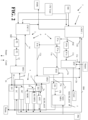
- Figure 2 is another schematic block diagram of the first exemplary embodiment of an apparatus 1 for providing cooling water for ammonia and/or hydrogen production that illustrates a more detailed exemplary arrangement of elements of the first exemplary embodiment of the apparatus 1, which can implement an exemplary process for providing cooling water for ammonia and hydrogen production.
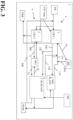
- Figure 3 is a schematic block diagram of a second exemplary embodiment of an apparatus 1 for providing cooling water for ammonia and/or hydrogen production.
- the schematic diagram of Figure 3 also illustrates exemplary processes for providing cooling water for ammonia and/or hydrogen production.
- an apparatus 1 for providing for cooling water for ammonia and/or hydrogen production can include an ammonia (NH3) plant 5 (NH3 PLANT) and a hydrogen production plant 7 (H2 PLANT), which can also be referred to herein as a hydrogen plant 7 (H2 PLANT).
- the ammonia plant 5 and hydrogen production plant 7 can be configured as green ammonia and green hydrogen production facilities that can utilize renewable power.
- the apparatus 1 can also include a plurality of cooling towers 3, which can include a first cooling tower 3 (CWT 1) and a second cooling tower 3 (CWT 2).
- the first cooling tower 3 can be a cooling tower that can have a pre-selected number of cooling cells for cooling a first stream of cooling water to a first pre-selected temperature.
- the second cooling tower 3 can have a pre-selected number of cooling cells for cooling a second stream of cooling water to a second pre-selected temperature that may be different from the first pre-selected temperature.
- the number of cells in each cooling tower 3 can be the same or can be different numbers of cells for different embodiments.
- the first cooling tower CWT 1 may have more cells than the second cooling tower CWT 2 such that the first cooling tower CWT 1 may be larger than the second cooling tower CWT 2.
- Other embodiments can utilize different types of cooling towers that are sized differently or of a different type.
- the first cooling tower CWT 1 may be larger than the second cooling tower CWT 2, but could also be of a similar size or even smaller depending on the overall design objectives.
- the first cooling tower CWT 1 can be arranged to receive sea water SW from a source of sea water and cool that water to a pre-selected first temperature for feeding a first stream of cooling water toward a steam turbine condenser STC, a first heat exchanger HX1, and a second heat exchanger HX2.
- the first pre-selected temperature can be a suitable temperature such as, for example, a temperature that is greater than 0°C and less than or equal to 40°C, a temperature that is between 5°C and 40°C (i.e., in a range from 5°C to 40°C), between 25°C and 30°C (i.e., in a range from 25°C to 30°C) or between 20°C and 30°C (i.e., in a range from 20°C to 30°C), e.g., less than or equal to 20°C to less than or equal to 30°C.
- a suitable temperature such as, for example, a temperature that is greater than 0°C and less than or equal to 40°C, a temperature that is between 5°C and 40°C (i.e., in a range from 5°C to 40°C), between 25°C and 30°C (i.e., in a range from 25°C to 30°C) or between 20°C and 30°C (i
- the first pre-selected temperature can be 10°C, 15°C, 20°C, 25°C, 28°C or 29°C or less than 30°C and more than 27°C.
- the sea water can be a pre-treated sea water (e.g., reverse osmosis and/or nanofiltration processed sea water, etc.).
- the first heat exchanger HX1 can include a single heat exchanger or a plurality of heat exchangers.
- the second heat exchanger HX2 can include a single heat exchanger or a plurality of heat exchangers.
- the steam turbine condenser STC can include a single heat exchanger or a plurality of heat exchangers configured for condensation of the steam via the third portion of the first stream.
- the first cooling tower CWT 1 can output the first stream of cooling water FSC at the first pre-selected temperature so that a first portion 11a of this first stream of cooling water FSC is fed to the first heat exchanger HX1, a second portion 11b of this first stream is fed to the second heat exchanger HX3 and a third portion 11c of this first stream is fed to the steam turbine condenser STC for cooling steam (Steam) fed therein so condensate (Cond.) can be output from the steam turbine condenser for being fed back toward the steam turbine.
- the first heat exchanger HX1 can be positioned to receive hot fluid from the ammonia manufacturing (NH3 MFG - see Figure 2 ) of the ammonia plant 5 (NH3 PLANT) for cooing that hot fluid via the first portion 11a of the first stream of cooling water FSC.
- the second heat exchanger HX2 can be positioned to receive hot fluid from various elements of the hydrogen production plant (H2 PLANT) for cooling that hot fluid via the second portion 11b of the first stream of cooling water FSC output from the first cooling tower CWT 1.
- the second heat exchanger HX2 can receive hot fluid from an air separation unit (ASU - see Figure 2 ), hydrogen manufacturing (H2 MFG - see Figure 2 ), and one or more transformer coolers and one or more rectifier coolers (T&RC - see Figure 2 ) of the hydrogen production plant 7 for cooling via the second portion 11b of the first stream of cooling water FSC output by the first cooling tower CWT 1.
- ASU air separation unit
- H2 MFG - see Figure 2 hydrogen manufacturing
- T&RC - see Figure 2 rectifier coolers of the hydrogen production plant 7 for cooling via the second portion 11b of the first stream of cooling water FSC output by the first cooling tower CWT 1.
- the second cooling tower CWT 2 can be arranged and configured to receive sea water SW from the source of sea water and cool that sea water to a second pre-selected temperature to provide the cooled sea water as a second stream 12 of cooling water SSC for feeding to a third heat exchanger HX3.
- the second pre-selected temperature can be a suitable temperature that is also higher than the first pre-selected temperature such as, for example, a temperature between 10°C and 60°C ( i.e., in a range from 10°C to 60°C), between 20°C and 40°C ( i.e., in a range from 20°C to 40°C), between 30°C and 35°C ( i.e., in a range from 30°C to 35°C) or between 30°C and 50°C ( i.e., in a range from 30°C to 50°C), e.g., less than or equal to 30°C to less than or equal to 40°C.
- the second pre-selected temperature can be 15°C, 20°C, 25°C, 30°C, 31 °C or 32°C or greater than 30°C and less than 35°C when that temperature is also higher than the first pre-selected temperature.
- the second pre-selected temperature can be a temperature that is as much as 1 °C to 40°C higher than the first pre-selected temperature or the second pre-selected temperature can be a temperature that is as much as 2°C to 50°C higher than the first pre-selected temperature.
- the third heat exchanger HX3 can include a single heat exchanger or a plurality of heat exchangers.
- the third heat exchange HX3 can be configured to receive hot fluid from gas coolers (GC - see Figure 2 ) and/or electrolyte coolers (EC - see Figure 2 ) of the hydrogen production plant 5 (H2 PLANT) for cooling via the second stream of cooling water SSC received from the second cooling tower CWT 2.
- the second pre-selected temperature of the second stream of cooling water SSC output from the second cooling tower CWT 2 can be a temperature that is higher than the first pre-selected temperature of the first stream of cooling water output from the first cooling tower CWT 1.
- the second pre-selected temperature can be 32°C or other suitable temperature (e.g., a temperature between 30°C and 40°C ( i.e., in a range from 30°C to 40°C) or a temperature between 30°C and 35°C ( i.e., in a range from 30°C to 35°C) or other suitable temperature that is higher than the first pre-selected temperature, etc.) while the first pre-selected temperature can be 29°C or another suitable temperature that is lower than the second pre-selected temperature ( e.g., a temperature between 25°C and 30°C ( i.e., in a range from 25°C to 30°C) or a temperature between 20°C and 30°C ( i.e.
- the warmed second stream of cooling water 14 output from the third heat exchanger HX3 can be recycled back to the second cooling tower CWT 2 as heated water that can be subsequently cooled back to the second pre-selected temperature for using that recycled water to form the second stream of cooling water.
- the second cooling tower CWT 2 can also output a flow of output water that can be output for subsequent use as a sea water recovery SWR stream. This stream can be output back to a source of sea water or fed to another plant process for dehydration or evaporation so salt can be formed from the sea water recovery stream SWR and no liquid sea water may need to be returned to an external body of water (or only a minimal amount of such liquid may ultimately need to be returned).
- the warmed first, second, and third portions of the first stream of cooling water can be output from the first heat exchanger HX1, second heat exchanger HX2 and steam turbine condenser STC for being returned to the first cooling tower CWT 1 to be cooled back to the first pre-selected temperature for being output as the first stream of cooling water FSC in a closed circuit arrangement to help minimize the need for additional added water as makeup water in the first cooling circuit.
- the first cooling tower CWT 1 can also output a flow of output water that can be output for subsequent use as a sea water recovery SWR stream.
- This stream can be output back to a source of sea water or fed to another plant process for dehydration or evaporation so salt can be formed from the sea water recovery stream SWR and no liquid sea water may need to be returned to an external body of water (or only a minimal amount of such liquid may ultimately need to be returned).
- the apparatus 1 can also include other elements.
- cooling water treatment may be provided from a source of treatment material.
- the cooling water treatment elements can include anti-corrosion material (e.g., corrosion inhibitors) and/or anti-microbial materials (e.g., germ inhibiting material) that can be injected into each cooling tower (e.g., first cooling tower CWT 1 and second cooling tower CWT 2) or into the feed of water fed to those towers to help prevent corrosion and/or formation of bacteria, mold, or other germs or microbial agents.
- a source of potable water (PW) can provide additional water to elements of the ammonia plant 5 and/or the hydrogen plant 7. This potable water can be demineralized prior to being fed to different elements of the ammonia plant 5 and/or the hydrogen plant 7.
- a portion of condensate can be output from the hydrogen plant 7 for being fed to the feed stream of water to be fed to the first cooling tower CWT 1 and/or second cooling tower CWT 2 as a recycle stream RW.
- This output condensate can include water, be comprised mostly of water, or be entirely water.
- the ammonia plant 5 and hydrogen plant 7 can also output waste streams of water or waste streams that include water (Waste). This waste can be output for treatment or disposal via a wastewater treatment process or other type of suitable disposal process.
- Figure 2 illustrates a more detailed schematic illustration of an exemplary embodiment of the apparatus 1 for providing cooling water for ammonia and hydrogen production shown in Figure 1 and discussed above. It should be appreciated that other designs can also be utilized as an alternative or as an addition to what is shown in the exemplary embodiment of Figure 2 .
- the first cooling tower CWT 1 can be included in a first cooling circuit 4 and the second cooling tower CWT 2 can be included in a second cooling circuit 6.
- Cooling water treatment material can also be fed to the first and second cooling towers CWT 1 and CWT 2 to help avoid corrosion and formation of microbial agents (e.g., as noted above) via a treatment feed conduit arrangement positioned between a source of the treatment material and the first and second cooling towers CWT 1 and CWT 2.
- the treatment material can be directly fed to each cooling tower or can be fed to the feed water prior to that water being fed to the cooling towers.
- the first cooling tower CWT 1 can cool the water fed therein to output a first stream of cooling water having a first pre-selected temperature.
- this first pre-selected temperature can be any suitable temperature.
- this first pre-selected temperature can be a temperature that is greater than 0°C and less than or equal to 40°C, between 25°C and 30°C (i.e., in a range from 25°C to 30°C), between 20°C and 30°C (i.e., in a range from 20°C to 30°C), e.g., less than or equal to 20°C to less than or equal to 30°C, or other suitable temperature that is less than the second pre-selected temperature.
- the first pre-selected temperature can be 10°C, 20°C, 25°C, 28°C, or 29°C or less than 30°C and more than 27°C, etc.
- the first pre-selected temperature can be lower than a second pre-selected temperature of the second stream of cooling water SSC that can be output from the second cooling tower CWT 2.
- the first stream of cooling water FSC can be split into a first portion 11a, a second portion 11b, and a third portion 11c.
- the splitting can occur after the first stream of cooling water FSC is passed through at least one pump and at least one filtration device or can occur prior to any portions of the first stream of cooling water FSC being passed through a pump or filtration device.
- the first stream of cooling water FSC can be split so that a some of the first stream of cooling water FSC is fed to a first pump P1a and the remainder of that first stream of cooling water FSC is fed to a second pump P1b.
- the cooling water output from the first pump P1a can be split into a first portion 11a and a second portion 11b.
- the hot fluid stream 7a can include water or be mostly water (e.g., entirely water, almost entirely water, etc.) in some embodiments.
- the hydrogen manufacturing (H2 MFG) can include electrolyzers.
- the transformer and rectifier coolers (T&RC) of the hydrogen plant 7 can include one or more transformer coolers and one or more rectifier coolers.
- the first heat exchanger HX1 can output the cooled ammonia manufacturing fluid 15a and feed that fluid to a first expansion drum D1 for that fluid to subsequently be fed back to the ammonia manufacturing (NH3 MFG) for subsequent use.
- the first expansion drum D1 can be a tank or other type of vessel sized to accommodate thermal expansion of water or other fluid in the closed loop arrangement of the first cooling circuit 4.
- a first drum output conduit arrangement 15b can be positioned between the first heat exchanger HX1 and the ammonia manufacturing to facilitate the flow of the cooled fluid back to the ammonia manufacturing elements.
- the second heat exchanger HX2 can output the cooled hydrogen plant fluid 17 and feed that fluid to a second expansion drum D2 for that fluid to subsequently be fed back to the ASU, hydrogen manufacturing (H2 MFG) and transformer and rectifier coolers (T&RC) for subsequent use.
- the second expansion drum D2 can be a tank or other type of vessel sized to accommodate thermal expansion of water or other fluid in the closed loop arrangement of the first cooling circuit 4.
- a second drum output conduit arrangement 19 can be positioned between the second heat exchanger HX2 and the ASU, hydrogen manufacturing, and transformer and rectifier coolers T&RC to facilitate the flow of the cooled fluid back to these elements.
- a third portion 11c of the first stream of cooling water FSC can be fed to a second pump P1b and a third filtration device F1c before that third portion is fed to the steam turbine condenser STC for functioning as a cooling medium therein to condense steam received by the steam turbine condenser STC for forming condensate (Cond).
- the third filtration device F1c can be positioned between the second pump P1b and the steam turbine condenser STC.
- the warmed first portion 13a of the first stream of cooling water FSC output from the first heat exchanger, warmed second portion 13b of the first stream of cooling water FSC output from the second heat exchanger HX2, and the warmed third portion 13c of the first stream of cooling water FSC output from the steam turbine condenser STC can be fed back to the first cooling tower CWT1 as at least one recycled water stream 13d.
- a first stream of cooling water conduit arrangement can be positioned to fluidly connect the first cooling tower CWT 1 to the pumps, filtration devices, heat exchangers, and steam turbine condenser STC for feeding the first stream of cooling water to these elements and having the warm cooling water output from these elements returned back to the first cooling tower for subsequent cooling in a closed circuit arrangement.
- the first cooling tower CWT 1 and its related elements for providing cooling can be considered part of a first cooling circuit 4 of the first cooling tower CWT 1.
- the second cooling tower CWT 2 can cool the water fed therein to output a second stream of cooling water SSC having a second pre-selected temperature.
- this second pre-selected temperature can be any suitable temperature.
- this second pre-selected temperature can be a temperature that is between 10°C and 60°C (i.e., in a range from 10°C to 60°C), between 30°C and 35°C (i.e., in a range from 30°C to 35°C) or between 30°C and 50°C (i.e., in a range from 30°C to 50°C), e.g., less than or equal to 30°C to less than or equal to 40°C, less than or equal to 30°C to less than or equal to 50°C, etc.
- the second pre-selected temperature can be a temperature that is as much as between 1 °C and 40°C (i.e., in a range from 1°C to 40°C) greater than the first pre-selected temperature.
- the second pre-selected temperature can also be another suitable temperature (or suitable temperature within another suitable temperature range) that is also higher than the first pre-selected temperature.
- the second cooling tower CWT 2 can be a component of a second cooling circuit 6.
- the second cooling circuit 6 can be arranged and positioned so that the second stream of cooling water SSC output from the second cooling tower at the second pre-selected temperature can be fed to a third pump P2 and a fourth filtration device F2.
- the third pump P2 can be considered a first pump P2 of the second cooling circuit 6 and the fourth filtration device F2 can be considered a first filtration device of the second cooling circuit.
- the filtered second stream of cooling water can be fed as a cooling medium feed 12 to the third heat exchanger HX3 for functioning as a cooling medium therein.
- the warmed cooling water 14 output from the third heat exchanger can be fed back to the second cooling tower for subsequent cooling back to the second pre-selected temperature via the second cooling tower CWT 2.
- a conduit arrangement can be included in the second cooling circuit 6 to facilitate the flow of the second stream of cooling water from the second cooling tower CWT 2 to the third heat exchanger HX3 as well as the return of the warmed cooling water output from the third heat exchanger HX3 back to the second cooling tower CWT 2 so this water is transported in a closed circuit arrangement to help minimize the need for additional added water as makeup water in the circuit.
- the third heat exchanger HX3 can receive at least one hot fluid stream 7b from gas coolers GC and electrolyte coolers EC of the hydrogen plant 7 for cooling therein.
- the hot fluid stream 7b can be hotter water or include hotter water, for example (e.g., be entirely water, almost entirely water, or mostly include water, etc.).
- the electrolyte coolers EC can include one or more anolyte coolers and one or more catholyte coolers.
- the gas coolers GC can include at least one hydrogen gas coolers and/or at least one oxygen gas cooler.
- the cooled fluid received from the gas coolers GC and electrolyte coolers EC of the hydrogen plant 7 can be output from the third heat exchanger as a cooled fluid stream 16 for feeding to a third expansion drum D3 for that fluid to subsequently be fed back to the gas coolers GC and electrolyte coolers EC of the hydrogen plant 7 for subsequent use.
- the third expansion drum D3 can be a tank or other type of vessel sized to accommodate thermal expansion of water or other fluid in the closed loop arrangement of the second cooling circuit 6.
- a third drum output conduit arrangement 20 can be positioned between the third heat exchanger HX3 and the gas coolers GC and electrolyte coolers EC of the hydrogen plant 7 to facilitate the flow of the cooled fluid back to these elements.
- the ammonia plant 5 can also output at least one waste stream.
- Th ASU, hydrogen manufacturing (H2 MFG), transformer and rectifier coolers, gas coolers, and electrolyte coolers of the hydrogen plant can also output at least one waste stream for being output for wastewater treatment or other waste treatment (Waste).
- the ammonia manufacturing (NH3 MFG) and electrolyte coolers EC can also receive potable water from a source of potable water PW.
- Condensate output from one or more of the elements of the hydrogen plant 7 can be output from the hydrogen plant and fed back to the first cooling tower CWT 1 to provide additional makeup water as a liquid recycle stream RW to help reduce the need for additional fresh sea water to be fed to a cooling tower to account for evaporation or other water loss that may occur over time.
- This recycle stream RW can also, or alternatively, provide liquid to the second cooling tower as well (not shown in Figure 2 ).
- the first, second, and third heat exchanges HX1, HX2, and HX3 can be arranged and configured to receive cooling water for cooling one or more process streams.
- the first heat exchanger HX1 can be positioned and configured to receive at least one hotter fluid stream 5a the first heat exchanger HX1 receives from ammonia manufacturing (NH3 MFG) of the ammonia plant 5 at a first ammonia manufacturing fluid temperature and output that cooled ammonia manufacturing fluid 15a at a first heat exchanger output temperature that is a lower temperature.
- This hotter fluid stream 5a can include water or be comprised mostly of water (e.g., be entirely water or almost entirely water).
- This temperature difference between the hot ammonia manufacturing fluid fed to the first heat exchanger HX1 and the temperature of the cooled ammonia manufacturing fluid 15a output from the first heat exchanger HX1 can be at least 3°C, at least 5°C or be in a range from 3°C to 15°C in some embodiments. Other temperature differences can also be utilized to meet a particular set of design criteria.
- the second heat exchanger HX2 can be positioned and configured to receive at least one hotter fluid stream 7a the second heat exchanger HX2 receives from the ASU, hydrogen manufacturing (H2 MFG) and transformer and rectifier coolers T&RC of the hydrogen plant 7 at a first hydrogen plant fluid inlet temperature and output that cooled hydrogen plant fluid 17 at a second heat exchanger output temperature that is a lower temperature.
- This temperature difference between the hotter fluid 7a fed to the second heat exchanger HX2 and the temperature of the cooled hydrogen plant fluid 17 output from the second heat exchanger HX2 can be at least 5°C, at least 10°C or be in a range from 5° to 25°C in some embodiments. Other temperature differences can also be utilized to meet a particular set of design criteria.
- the fluid of the at least one hotter fluid stream 7a can include water or be water in some embodiments.
- the third heat exchanger HX3 can be positioned and configured to receive at least one hotter fluid stream 7b the third heat exchanger HX3 receives from the gas coolers GC and electrolyte coolers EC of the hydrogen plant 7 at a second hydrogen plant fluid inlet temperature and output that cooled hydrogen plant fluid 16 at a third heat exchanger output temperature that is a lower temperature.
- This temperature difference between the hotter fluid 7b fed to the third heat exchanger HX3 and the temperature of the cooled hydrogen plant fluid 16 output from the third heat exchanger HX3 can be at least 10°C, at least 25°C or be in a range from 5° to 40°C in some embodiments. Other temperature differences can also be utilized to meet a particular set of design criteria.
- the fluid of the at least one hotter fluid stream 7b can include water or be water in some embodiments.
- Each of the first, second, and third heat exchangers HX1, HX2, and HX3 can be structured as any type of suitable heat exchanger.
- these heat exchangers can each include one or more plate heat exchangers, one or more shell and tube heat exchangers, one or more finned tube heat exchangers, or include combinations of these types of heat exchangers.
- each of the pumps can be a single pump or include a plurality of pumps for driving the flow of cooling water at a desired flow rate and/or pressure.
- the operational conditions for the first and second cooling circuits 4 and 6, heat exchanges, and other elements can be adjusted to meet a particular set of design criteria. The pressure, temperature and flow rates for various process streams or units may therefore be adapted to meet the needs of a particular implementation.
- the first and second cooling towers CWT 1 and CWT 2 can each output a flow of water as a sea water recovery stream SWR. This stream can be used for further use in a plant or can be output for delivery to a body of water that may be the source of the sea water.
- the first and second cooling towers CWT 1 and CWT 2 can be positioned and configured for use for hydrogen production (e.g., green hydrogen production, production of hydrogen for a hydrogen supply line, production of liquid hydrogen, etc.).
- the ammonia manufacturing related elements may not be included in the embodiments.
- such embodiments may not utilize the ammonia plant (NH3 Plant) 5 or the first heat exchanger HX1.
- the second heat exchanger HX2 can be considered a first heat exchanger and the third heat exchanger HX3 can be considered a second heat exchanger.
- the entire first stream of cooling water FSC can be fed to the second heat exchanger HX2 or can be fed to the second heat exchanger HX2 and the steam turbine condenser STC so there may not be conduit arrangements associated with the first portion 11a of the first stream of the cooling water FSC as well as other elements associated with the first portion 11a of the first stream of cooling water FSC, etc. ) .
- Embodiments of the apparatus 1 can provide significant operational improvements and fabrication improvements.
- the utilization of multiple cooling circuits each having at least one cooling tower can permit the cooling towers to be smaller sized for lower capital costs for those units and can also permit cooling water to be provided at multiple different cooling temperatures (e.g., the above noted first pre-selected temperature and second pre-selected temperature).
- Embodiments can permit a smaller second cooling tower CWT 2 to be utilized, which can also provide a significant portion of the cooling provided by the cooling water of the apparatus 1 (e.g., over 50% of the overall cooling, between 45% and 60% ( i.e., in a range from 45% to 60%) of the overall cooling, at least 50% of the overall cooling, more than 45% of the overall cooling and less than 80% of the overall cooling, etc.).
- the combination of the smaller second cooling tower CWT 2 that can provide a hotter cooling water outlet temperature suitable for use by various elements of the hydrogen plant 7 can provide significant operational flexibility, reduced capital costs, and allow a large amount of water utilized in the cooling for the ammonia plant 5 and hydrogen plant 7 to be avoid being overcooled to an unnecessarily low temperature.
- Such features can permit smaller cooling towers to be used ( e.g., simpler, less costly devices that can be easier and less costly to build, use and maintain) and also permit a more efficient use of the cooling water by providing different sources of cooling mediums for use in cooling different process streams.
- the utilization of multiple closed loop cooling circuits such as the exemplary first cooling circuit 4 and second cooling circuit 6 discussed above can also provide safety and maintenance features. For instance, if an accident or leak occurs that may affect the ammonia plant 5 (e.g., a leak of ammonia that could get into the fluid of the first cooling circuit 4), the ammonia plant 5 can be shut down without affecting hydrogen production of the hydrogen plant 7 or requiring a shutdown of the second cooling circuit 6.
- an accident or leak that may affect the ammonia plant 5 (e.g., a leak of ammonia that could get into the fluid of the first cooling circuit 4)
- the ammonia plant 5 can be shut down without affecting hydrogen production of the hydrogen plant 7 or requiring a shutdown of the second cooling circuit 6.
- embodiments can permit the various conduits utilized in the apparatus 1 for the transport of the fluids to be cooled via first, second, and third heat exchangers HX1, HX2, and HX3, as well as the conduits used to convey the first and second streams of cooling water FSC and SSC to and from the cooling towers 3 to be substantially smaller in size.
- conduits can include diameters not more than 3 meters in diameter (e.g., the largest conduits in the cooling circuits can be no more than 3 meters, less than 2.7 meters or less than 1.9 meters in diameter at their largest sizes).
- This size reduction also permits the other elements to be sized smaller (e.g., smaller heat exchangers, etc.).
- Such embodiments can avoid requiring use of customized sized piping or valves or other specialty equipment to accommodate very large diameter conduits, which can reduce capital costs and also permit fabrication of a plant or apparatus 1 to be performed much more quickly and more efficiently.
- Embodiments can also be adapted to help minimize the amount of water that may be output from the cooling towers 3 for return to a body of water. Some embodiments may fully eliminate such water while others may minimize it. Embodiments can provide flexibility so a large part, if not all, of such water can be dehydrated to form salt. If water is output for return to a source of the water (e.g., a sea, etc.), the output can be limited so that it can minimize the ecological impact associated with the output of too much hot water back to a body of water ( e.g., avoid algae blooms, etc.).
- a source of the water e.g., a sea, etc.
- the output can be limited so that it can minimize the ecological impact associated with the output of too much hot water back to a body of water (e.g., avoid algae blooms, etc.).
- Embodiments can also be provided that can limit the types of corrosion inhibitor and antimicrobial agents provided as cooling water treatment material (CW Treat) so that such salt that is formed can be considered safe for human consumption or safe for animal consumption in some implementations.
- CW Treat cooling water treatment material
- Embodiments can also permit the first and second cooling circuits 4 and 6 to be utilized in a manner that can help eliminate the need for additional cooling loops for some plant specific equipment (e.g., electrolyzers of the hydrogen plant 7). By providing for a recycling of warmed water output from the heat exchangers, embodiments can also provide a reduction in fresh water additions needed for the cooling circuits so that a reduction in water use may also be provided.
- plant specific equipment e.g., electrolyzers of the hydrogen plant 7
- Embodiments can utilize sea water or fresh water.
- the treated sea water can be desalinated water or the source of the cooling water can be water from a fresh water source (e.g., a river).
- the first and second heat exchangers HX1 and HX2 may not be needed or utilized.
- the third heat exchanger HX3 can be considered a first heat exchanger HX3. An example of such an embodiment is shown in Figure 3 .
- the apparatus 1 for providing for cooling water for ammonia and/or hydrogen production can include the ammonia (NH3) plant 5 (NH3 PLANT) and the hydrogen production plant 7 (H2 PLANT).
- the apparatus 1 can also include a plurality of cooling towers 3, which can include a first cooling tower 3 (CWT 1) and a second cooling tower 3 (CWT 2).
- the first cooling tower 3 (CWT 1) can be a cooling tower that can have a pre-selected number of cooling cells for cooling a first stream of cooling water to a first pre-selected temperature.
- the second cooling tower 3 (CWT 2) can have a pre-selected number of cooling cells for cooling a second stream of cooling water to a second pre-selected temperature that may be different from the first pre-selected temperature.
- the first cooling tower 3 (CWT 1) can be part of a first cooling circuit 4 and the second cooling tower 3 (CWT 2) can be part of a second cooling circuit 6.
- the number of cells in each cooling tower 3 can be the same or can be different numbers of cells for different embodiments.
- the first cooling tower CWT 1 may have more cells than the second cooling tower CWT 2 such that the first cooling tower CWT 1 may be larger than the second cooling tower CWT 2.
- Other embodiments can utilize different types of cooling towers that are sized differently or of a different type.
- the first cooling tower CWT 1 may be larger than the second cooling tower CWT 2, but could also be of a similar size or even smaller depending on the overall design objectives.
- the first cooling tower CWT 1 can be arranged to receive fresh water FW from a source of fresh water (e.g., lake, river, etc.) and cool that water to a pre-selected first temperature for feeding a first stream of cooling water toward a steam turbine condenser STC, the ammonia plant 5 (NH3 PLANT) and the hydrogen production plant 7 (H2 PLANT) for cooling plant elements of the ammonia plant 5 and/or hydrogen production plant 7 and use in the steam turbine condenser STC.
- a source of fresh water e.g., lake, river, etc.
- H2 PLANT hydrogen production plant 7
- the first pre-selected temperature can be a suitable temperature such as, for example, a temperature that is greater than 0°C and less than or equal to 40°C, a temperature that is between 5°C and 40°C ( i.e., in a range from 5°C to 40°C), between 25°C and 30°C ( i.e., in a range from 25°C to 30°C) or between 20°C and 30°C ( i.e., in a range from 20°C to 30°C), e.g., less than or equal to 20°C to less than or equal to 30°C.
- a suitable temperature such as, for example, a temperature that is greater than 0°C and less than or equal to 40°C, a temperature that is between 5°C and 40°C ( i.e., in a range from 5°C to 40°C), between 25°C and 30°C ( i.e., in a range from 25°C to 30°C) or between 20°C and
- the first pre-selected temperature can be 10°C, 15°C, 20°C, 25°C, 28°C or 29°C or less than 30°C and more than 27°C.
- the fresh water can be a pre-treated fresh water (e.g., reverse osmosis and/or nanofiltration processed sea water, etc.).
- the steam turbine condenser STC can include a single heat exchanger or a plurality of heat exchangers configured for condensation of the steam via the third portion of the first stream.
- the first portion 11a can be fed to ammonia manufacturing (NH3 MFG) of the ammonia plant 5 (NH3 PLANT) for cooing hot fluid and/or process elements of the ammonia manufacturing via the first portion 11a of the first stream of cooling water FSC.
- the second portion 11b can be fed to the hydrogen production plant (H2 PLANT) 7 to cool hot fluid from one or more various elements of the hydrogen production plant (H2 PLANT) or to process units of that plant for cooling via the second portion 11b of the first stream of cooling water FSC output from the first cooling tower CWT 1.
- hot fluid from an air separation unit (ASU), hydrogen manufacturing (H2 MFG), and one or more transformer coolers and one or more rectifier coolers (T&RC) of the hydrogen production plant 7 can receive the second portion 11b to function as a cooling medium via the second portion 11b of the first stream of cooling water FSC output by the first cooling tower CWT 1.
- ASU air separation unit
- H2 MFG hydrogen manufacturing
- T&RC rectifier coolers
- the second cooling tower CWT 2 can be arranged and configured to receive fresh water FW from the source of fresh water and cool that fresh water to a second pre-selected temperature to provide the cooled fresh water as a second stream of cooling water SSC for feeding to a third heat exchanger HX3.
- the third heat exchanger HX3 can be considered a first heat exchanger in this embodiment since the first and second heat exchangers HX1 and HX2 are not utilized in this embodiment.
- the second pre-selected temperature can be a suitable temperature that is also higher than the first pre-selected temperature such as, for example, a temperature between 10°C and 60°C( i.e ., in a range from 10°C to 60°C), between 20°C and 40°C ( i.e., in a range from 20°C to 40°C), between 30°C and 35°C ( i.e., in a range from 30°C to 35°C) or between 30°C and 50°C ( i.e., in a range from 30°C to 50°C), e.g., less than or equal to 30°C to less than or equal to 40°C.
- the second pre-selected temperature can be 15°C, 20°C, 25°C, 30°C, 31°C or 32°C or greater than 30°C and less than 35°C when that temperature is also higher than the first pre-selected temperature.
- the second pre-selected temperature can be a temperature that is as much as 1 °C to 40°C higher than the first pre-selected temperature or the second pre-selected temperature can be a temperature that is as much as 2°C to 50°C higher than the first pre-selected temperature.
- the second pre-selected temperature of the second stream of cooling water SSC output from the second cooling tower CWT 2 can be a temperature that is higher than the first pre-selected temperature of the first stream of cooling water output from the first cooling tower CWT 1.
- the second pre-selected temperature can be 32°C or other suitable temperature (e.g., a temperature between 30°C and 40°C ( i.e., in a range from 30°C to 40°C) or a temperature between 30°C and 35°C ( i.e., in a range from 30°C to 35°C) or other suitable temperature that is higher than the first pre-selected temperature, etc.) while the first pre-selected temperature can be 29°C or another suitable temperature that is lower than the second pre-selected temperature ( e.g., a temperature between 25°C and 30°C ( i.e., in a range from 25°C to 30°C) or a temperature between 20°C and 30°C ( i.e.
- the warmed second stream of cooling water 14 output from the heat exchanger HX3 can be recycled back to the second cooling tower CWT 2 as heated water that can be subsequently cooled back to the second pre-selected temperature for using that recycled water to form the second stream of cooling water.
- the second cooling tower CWT 2 can also output a flow of output water that can be output for subsequent use as a fresh water recovery FWR stream. This stream can be output back to a source of fresh water or fed to another plant process for dehydration or evaporation and no liquid fresh water may need to be returned to an external body of water (or only a minimal amount of such liquid may ultimately need to be returned).
- the warmed first, second, and third portions of the first stream of cooling water can be output from the ammonia plant 5 (NH3 PLANT) as warmed first portion of 11A, output from the hydrogen production plant 7 (H2 PLANT) as warmed second portion 11H, and steam turbine condenser STC as warmed third portion 11STC for being returned to the first cooling tower CWT 1 to be cooled back to the first pre-selected temperature for being output as the first stream of cooling water FSC in a closed circuit arrangement to help minimize the need for additional added water as makeup water in the first cooling circuit or in an open circuit arrangement.
- the first cooling tower CWT 1 can also output a flow of output water that can be output for subsequent use as a fresh water recovery FWR stream. This stream can be output back to a source of fresh water or fed to another plant process for dehydration or evaporation so no liquid fresh water may need to be returned to an external body of water (or only a minimal amount of such liquid may ultimately need to be returned).
- cooling water treatment may be provided from a source of treatment material.
- the cooling water treatment elements can include anti-corrosion material (e.g., corrosion inhibitors) and/or anti-microbial materials (e.g., germ inhibiting material) that can be injected into each cooling tower (e.g., first cooling tower CWT 1 and second cooling tower CWT 2) or into the feed of water fed to those towers to help prevent corrosion and/or formation of bacteria, mold, or other germs or microbial agents.
- a source of potable water PW
- PW potable water
- This potable water can be demineralized prior to being fed to different elements of the ammonia plant 5 and/or the hydrogen plant 7.
- a portion of condensate can be output from the hydrogen plant 7 for being fed to the feed stream of water to be fed to the first cooling tower CWT 1 and/or second cooling tower CWT 2 as a recycle stream RW as well.
- This output condensate can include water, be comprised mostly of water, or be entirely water.
- the ammonia plant 5 and hydrogen plant 7 can also output waste streams of water or waste streams that include water (Waste). This waste can be output for treatment or disposal via a wastewater treatment process or other type of suitable disposal process.
- some embodiments can be utilized only for hydrogen production via the hydrogen production plant 7 (H2 PLANT).
- the ammonia plant 5 (HN3) plant and the formation of the first portion 11a (and return of the warmed first portion 11A) may not be utilized.
- the second portion 11b and the third portion 11c of the first stream of cooling water FSC can be utilized.
- the third portion 11c of the first stream of cooling water FSC that is fed to the steam turbine condenser STC can be considered a first portion or a second portion of the first stream of cooling water FSC.
- the portion of the first stream of cooling water FSC fed to the steam turbine condenser STC is considered a second portion
- the second portion 11b can be considered a first portion of the first stream of cooling water FSC.
- Embodiments of our apparatus, system, and process can provide significant improvements in operational flexibility, significantly improved profitability by reducing capital costs for providing cooling water for use in hydrogen production and ammonia production, and also provide maintenance and safety benefits associated with implementation and operation. Further, embodiments can be adapted to improve the environmental impact that ammonia production and/or hydrogen generation industrial processes may have by reducing or avoiding how much heated cooling water output from a cooling tower may be output for feeding back to a body of water.
- valves, piping, and other conduit elements e.g., conduit connection mechanisms, tubing, seals, etc.
- conduit connection mechanisms e.g., conduit connection mechanisms, tubing, seals, etc.
- flow rate, pressure, and temperature of the fluid passed through the various apparatus or system elements can vary to account for different design configurations and other design criteria.
- Embodiments of a plant can each be configured to include process control elements positioned and configured to monitor and control operations (e.g., temperature and pressure sensors, flow sensors, an automated process control system having at least one work station that includes a processor, non-transitory memory and at least one transceiver for communications with the sensor elements, valves, and controllers for providing a user interface for an automated process control system that may be run at the work station and/or another computer device of the plant, etc. ) .
- process control elements positioned and configured to monitor and control operations (e.g., temperature and pressure sensors, flow sensors, an automated process control system having at least one work station that includes a processor, non-transitory memory and at least one transceiver for communications with the sensor elements, valves, and controllers for providing a user interface for an automated process control system that may be run at the work station and/or another computer device of the plant, etc. ) .
Landscapes
- Chemical & Material Sciences (AREA)
- Organic Chemistry (AREA)
- Chemical Kinetics & Catalysis (AREA)
- Engineering & Computer Science (AREA)
- Inorganic Chemistry (AREA)
- Analytical Chemistry (AREA)
- Electrochemistry (AREA)
- Materials Engineering (AREA)
- Metallurgy (AREA)
- Automation & Control Theory (AREA)
- Thermal Sciences (AREA)
- General Engineering & Computer Science (AREA)
- Mechanical Engineering (AREA)
- Physics & Mathematics (AREA)
- Combustion & Propulsion (AREA)
- Hydrogen, Water And Hydrids (AREA)
- Electrolytic Production Of Non-Metals, Compounds, Apparatuses Therefor (AREA)
- Physical Or Chemical Processes And Apparatus (AREA)
Applications Claiming Priority (1)
| Application Number | Priority Date | Filing Date | Title |
|---|---|---|---|
| US18/085,690 US20240207802A1 (en) | 2022-12-21 | 2022-12-21 | Apparatus and process to provide cooling water for ammonia and or hydrogen productions |
Publications (2)
| Publication Number | Publication Date |
|---|---|
| EP4414321A2 true EP4414321A2 (fr) | 2024-08-14 |
| EP4414321A3 EP4414321A3 (fr) | 2025-01-29 |
Family
ID=89224546
Family Applications (1)
| Application Number | Title | Priority Date | Filing Date |
|---|---|---|---|
| EP23217998.6A Pending EP4414321A3 (fr) | 2022-12-21 | 2023-12-19 | Appareil et procédé pour fournir de l'eau de refroidissement pour la production d'ammoniac et/ou d'hydrogène |
Country Status (7)
| Country | Link |
|---|---|
| US (1) | US20240207802A1 (fr) |
| EP (1) | EP4414321A3 (fr) |
| CN (1) | CN118223055A (fr) |
| AU (1) | AU2023282308B2 (fr) |
| CA (1) | CA3223914A1 (fr) |
| CL (1) | CL2023003770A1 (fr) |
| MX (1) | MX2023015349A (fr) |
Families Citing this family (1)
| Publication number | Priority date | Publication date | Assignee | Title |
|---|---|---|---|---|
| WO2025024208A1 (fr) * | 2023-07-21 | 2025-01-30 | Air Products And Chemicals, Inc. | Système d'eau de refroidissement |
Citations (4)
| Publication number | Priority date | Publication date | Assignee | Title |
|---|---|---|---|---|
| WO2021089276A1 (fr) | 2019-11-08 | 2021-05-14 | Casale Sa | Contrôle d'une boucle de synthèse d'ammoniac à charge partielle |
| EP3957772A1 (fr) | 2020-07-28 | 2022-02-23 | Air Products And Chemicals, Inc. | Procédé et appareil pour générer, stocker et utiliser de l'hydrogène |
| WO2022089820A1 (fr) | 2020-10-30 | 2022-05-05 | Casale Sa | Contrôle d'une boucle de synthèse d'ammoniac à charge partielle |
| US20220290309A1 (en) | 2021-03-15 | 2022-09-15 | Air Products And Chemicals, Inc. | Process and Apparatus for Compressing Hydrogen Gas in a Centrifugal Compressor |
Family Cites Families (7)
| Publication number | Priority date | Publication date | Assignee | Title |
|---|---|---|---|---|
| FR1406884A (fr) * | 1964-09-07 | 1965-07-23 | Chemical Construction Corp | Procédé de compression de gaz |
| DE3690233T1 (fr) * | 1985-05-06 | 1987-05-14 | ||
| US5364439A (en) * | 1992-04-29 | 1994-11-15 | Union Oil Company Of California | Method to treat geothermal fluid streams |
| US20050265919A1 (en) * | 2004-05-28 | 2005-12-01 | H2Gen Innovations, Inc. | Method and apparatus for cooling in hydrogen plants |
| KR101200561B1 (ko) * | 2012-04-27 | 2012-11-13 | 주식회사 엑스에프씨 | 해수전해설비를 이용한 연료전지, 해수전해설비를 이용하여 가성소다, 암모니아, 요소, pvc의 제조방법 및 그 통합시스템 |
| US11512402B2 (en) * | 2013-02-21 | 2022-11-29 | Faramarz Bairamijamal | High pressure process for CO2 capture, utilization for heat recovery, power cycle, super-efficient hydrogen based fossil power generation and conversion of liquid CO2 with water to syngas and oxygen |
| US9562201B2 (en) * | 2014-06-28 | 2017-02-07 | Saudi Arabian Oil Company | Energy efficient apparatus employing energy efficient process schemes providing enhanced integration of gasification-based multi-generation and hydrocarbon refining facilities and related methods |
-
2022
- 2022-12-21 US US18/085,690 patent/US20240207802A1/en active Pending
-
2023
- 2023-12-14 MX MX2023015349A patent/MX2023015349A/es unknown
- 2023-12-15 CL CL2023003770A patent/CL2023003770A1/es unknown
- 2023-12-15 AU AU2023282308A patent/AU2023282308B2/en active Active
- 2023-12-19 CN CN202311750034.8A patent/CN118223055A/zh active Pending
- 2023-12-19 EP EP23217998.6A patent/EP4414321A3/fr active Pending
- 2023-12-20 CA CA3223914A patent/CA3223914A1/fr active Pending
Patent Citations (4)
| Publication number | Priority date | Publication date | Assignee | Title |
|---|---|---|---|---|
| WO2021089276A1 (fr) | 2019-11-08 | 2021-05-14 | Casale Sa | Contrôle d'une boucle de synthèse d'ammoniac à charge partielle |
| EP3957772A1 (fr) | 2020-07-28 | 2022-02-23 | Air Products And Chemicals, Inc. | Procédé et appareil pour générer, stocker et utiliser de l'hydrogène |
| WO2022089820A1 (fr) | 2020-10-30 | 2022-05-05 | Casale Sa | Contrôle d'une boucle de synthèse d'ammoniac à charge partielle |
| US20220290309A1 (en) | 2021-03-15 | 2022-09-15 | Air Products And Chemicals, Inc. | Process and Apparatus for Compressing Hydrogen Gas in a Centrifugal Compressor |
Also Published As
| Publication number | Publication date |
|---|---|
| AU2023282308A1 (en) | 2024-07-11 |
| US20240207802A1 (en) | 2024-06-27 |
| EP4414321A3 (fr) | 2025-01-29 |
| CL2023003770A1 (es) | 2024-07-19 |
| AU2023282308B2 (en) | 2025-12-18 |
| MX2023015349A (es) | 2024-06-24 |
| CN118223055A (zh) | 2024-06-21 |
| CA3223914A1 (fr) | 2024-06-21 |
Similar Documents
| Publication | Publication Date | Title |
|---|---|---|
| EP4414321A2 (fr) | Appareil et procédé pour fournir de l'eau de refroidissement pour la production d'ammoniac et/ou d'hydrogène | |
| CN102278784A (zh) | 一种分布式直混供热系统 | |
| CN110092444A (zh) | 一种处理scal型间接空冷系统循环水水质的方法 | |
| US9890948B2 (en) | Method for preheating feed water in steam power plants, with process steam outcoupling | |
| JP2015127594A (ja) | ボイラ給水システム | |
| CN204851350U (zh) | 一种利用电厂乏汽余热的生水加热系统 | |
| CN102910697A (zh) | 一种船用海水淡化装置 | |
| CN101721137A (zh) | 一种直饮水终端供水装置 | |
| JP4223985B2 (ja) | 熱化学的水素製造設備 | |
| BR102023026378A2 (pt) | Aparelho e processo para fornecer água de resfriamento para produção de amônia e/ou hidrogênio | |
| CN206616128U (zh) | 一种污泥处理换热系统 | |
| CN216497570U (zh) | 变换冷凝液汽提处理装置 | |
| CN212057890U (zh) | 一种流体预冷循环系统 | |
| JP4346776B2 (ja) | 高効率装置冷却システム及び冷却方法 | |
| CN210291842U (zh) | 一种多晶硅生产中的蒸汽循环利用系统 | |
| CN201554065U (zh) | 一种直饮水终端供水装置 | |
| CN107218593A (zh) | 造纸高温冷凝水回收利用系统 | |
| CN217584391U (zh) | 连排扩容器疏水热值回收利用装置 | |
| CN209069011U (zh) | 一种盐酸合成炉热能利用系统 | |
| CN219160325U (zh) | 一种热媒炉热力除氧器供水升温系统 | |
| CN101851038A (zh) | 一种高温凝结水降温除盐方法 | |
| CN212226998U (zh) | 一种工业供热系统 | |
| CN104819447A (zh) | 一种洁净蒸汽发生装置 | |
| CN218988992U (zh) | 一种纺织高温废水降温系统 | |
| CN217179375U (zh) | 一种甲烷转化夹套水利用装置 |
Legal Events
| Date | Code | Title | Description |
|---|---|---|---|
| PUAI | Public reference made under article 153(3) epc to a published international application that has entered the european phase |
Free format text: ORIGINAL CODE: 0009012 |
|
| STAA | Information on the status of an ep patent application or granted ep patent |
Free format text: STATUS: THE APPLICATION HAS BEEN PUBLISHED |
|
| AK | Designated contracting states |
Kind code of ref document: A2 Designated state(s): AL AT BE BG CH CY CZ DE DK EE ES FI FR GB GR HR HU IE IS IT LI LT LU LV MC ME MK MT NL NO PL PT RO RS SE SI SK SM TR |
|
| PUAL | Search report despatched |
Free format text: ORIGINAL CODE: 0009013 |
|
| AK | Designated contracting states |
Kind code of ref document: A3 Designated state(s): AL AT BE BG CH CY CZ DE DK EE ES FI FR GB GR HR HU IE IS IT LI LT LU LV MC ME MK MT NL NO PL PT RO RS SE SI SK SM TR |
|
| RIC1 | Information provided on ipc code assigned before grant |
Ipc: B01J 19/24 20060101ALN20241223BHEP Ipc: B01J 19/00 20060101ALN20241223BHEP Ipc: F28C 1/00 20060101ALI20241223BHEP Ipc: C01C 1/04 20060101ALI20241223BHEP Ipc: C01B 3/02 20060101AFI20241223BHEP |
|
| STAA | Information on the status of an ep patent application or granted ep patent |
Free format text: STATUS: REQUEST FOR EXAMINATION WAS MADE |
|
| 17P | Request for examination filed |
Effective date: 20250729 |
|
| RAV | Requested validation state of the european patent: fee paid |
Extension state: MA Effective date: 20250729 |