EP4414329A1 - Système de synthèse d'ammoniac basé sur une source d'hydrogène fluctuante et son procédé de commande - Google Patents
Système de synthèse d'ammoniac basé sur une source d'hydrogène fluctuante et son procédé de commande Download PDFInfo
- Publication number
- EP4414329A1 EP4414329A1 EP23212022.0A EP23212022A EP4414329A1 EP 4414329 A1 EP4414329 A1 EP 4414329A1 EP 23212022 A EP23212022 A EP 23212022A EP 4414329 A1 EP4414329 A1 EP 4414329A1
- Authority
- EP
- European Patent Office
- Prior art keywords
- hydrogen
- ammonia synthesis
- nitrogen
- hydrogen storage
- pressure
- Prior art date
- Legal status (The legal status is an assumption and is not a legal conclusion. Google has not performed a legal analysis and makes no representation as to the accuracy of the status listed.)
- Pending
Links
Images

Classifications
-
- C—CHEMISTRY; METALLURGY
- C01—INORGANIC CHEMISTRY
- C01C—AMMONIA; CYANOGEN; COMPOUNDS THEREOF
- C01C1/00—Ammonia; Compounds thereof
- C01C1/02—Preparation, purification or separation of ammonia
- C01C1/04—Preparation of ammonia by synthesis
-
- C—CHEMISTRY; METALLURGY
- C01—INORGANIC CHEMISTRY
- C01C—AMMONIA; CYANOGEN; COMPOUNDS THEREOF
- C01C1/00—Ammonia; Compounds thereof
- C01C1/02—Preparation, purification or separation of ammonia
- C01C1/04—Preparation of ammonia by synthesis
- C01C1/0405—Preparation of ammonia by synthesis from N2 and H2 in presence of a catalyst
- C01C1/0417—Preparation of ammonia by synthesis from N2 and H2 in presence of a catalyst characterised by the synthesis reactor, e.g. arrangement of catalyst beds and heat exchangers in the reactor
-
- B—PERFORMING OPERATIONS; TRANSPORTING
- B01—PHYSICAL OR CHEMICAL PROCESSES OR APPARATUS IN GENERAL
- B01J—CHEMICAL OR PHYSICAL PROCESSES, e.g. CATALYSIS OR COLLOID CHEMISTRY; THEIR RELEVANT APPARATUS
- B01J19/00—Chemical, physical or physico-chemical processes in general; Their relevant apparatus
- B01J19/0006—Controlling or regulating processes
- B01J19/0033—Optimalisation processes, i.e. processes with adaptive control systems
-
- B—PERFORMING OPERATIONS; TRANSPORTING
- B01—PHYSICAL OR CHEMICAL PROCESSES OR APPARATUS IN GENERAL
- B01J—CHEMICAL OR PHYSICAL PROCESSES, e.g. CATALYSIS OR COLLOID CHEMISTRY; THEIR RELEVANT APPARATUS
- B01J19/00—Chemical, physical or physico-chemical processes in general; Their relevant apparatus
- B01J19/08—Processes employing the direct application of electric or wave energy, or particle radiation; Apparatus therefor
- B01J19/087—Processes employing the direct application of electric or wave energy, or particle radiation; Apparatus therefor employing electric or magnetic energy
- B01J19/088—Processes employing the direct application of electric or wave energy, or particle radiation; Apparatus therefor employing electric or magnetic energy giving rise to electric discharges
-
- B—PERFORMING OPERATIONS; TRANSPORTING
- B01—PHYSICAL OR CHEMICAL PROCESSES OR APPARATUS IN GENERAL
- B01J—CHEMICAL OR PHYSICAL PROCESSES, e.g. CATALYSIS OR COLLOID CHEMISTRY; THEIR RELEVANT APPARATUS
- B01J4/00—Feed or outlet devices; Feed or outlet control devices
- B01J4/008—Feed or outlet control devices
-
- B—PERFORMING OPERATIONS; TRANSPORTING
- B01—PHYSICAL OR CHEMICAL PROCESSES OR APPARATUS IN GENERAL
- B01J—CHEMICAL OR PHYSICAL PROCESSES, e.g. CATALYSIS OR COLLOID CHEMISTRY; THEIR RELEVANT APPARATUS
- B01J8/00—Chemical or physical processes in general, conducted in the presence of fluids and solid particles; Apparatus for such processes
- B01J8/02—Chemical or physical processes in general, conducted in the presence of fluids and solid particles; Apparatus for such processes with stationary particles, e.g. in fixed beds
-
- C—CHEMISTRY; METALLURGY
- C01—INORGANIC CHEMISTRY
- C01B—NON-METALLIC ELEMENTS; COMPOUNDS THEREOF; METALLOIDS OR COMPOUNDS THEREOF NOT COVERED BY SUBCLASS C01C
- C01B3/00—Hydrogen; Gaseous mixtures containing hydrogen; Separation of hydrogen from mixtures containing it; Purification of hydrogen; Reversible storage of hydrogen
- C01B3/02—Production of hydrogen; Production of gaseous mixtures containing hydrogen
- C01B3/025—Preparation or purification of gas mixtures for ammonia synthesis
-
- C—CHEMISTRY; METALLURGY
- C01—INORGANIC CHEMISTRY
- C01C—AMMONIA; CYANOGEN; COMPOUNDS THEREOF
- C01C1/00—Ammonia; Compounds thereof
- C01C1/02—Preparation, purification or separation of ammonia
- C01C1/04—Preparation of ammonia by synthesis
- C01C1/0405—Preparation of ammonia by synthesis from N2 and H2 in presence of a catalyst
- C01C1/0482—Process control; Start-up or cooling-down procedures
-
- C—CHEMISTRY; METALLURGY
- C25—ELECTROLYTIC OR ELECTROPHORETIC PROCESSES; APPARATUS THEREFOR
- C25B—ELECTROLYTIC OR ELECTROPHORETIC PROCESSES FOR THE PRODUCTION OF COMPOUNDS OR NON-METALS; APPARATUS THEREFOR
- C25B1/00—Electrolytic production of inorganic compounds or non-metals
- C25B1/01—Products
- C25B1/02—Hydrogen or oxygen
- C25B1/04—Hydrogen or oxygen by electrolysis of water
-
- C—CHEMISTRY; METALLURGY
- C25—ELECTROLYTIC OR ELECTROPHORETIC PROCESSES; APPARATUS THEREFOR
- C25B—ELECTROLYTIC OR ELECTROPHORETIC PROCESSES FOR THE PRODUCTION OF COMPOUNDS OR NON-METALS; APPARATUS THEREFOR
- C25B9/00—Cells or assemblies of cells; Constructional parts of cells; Assemblies of constructional parts, e.g. electrode-diaphragm assemblies; Process-related cell features
- C25B9/60—Constructional parts of cells
- C25B9/65—Means for supplying current; Electrode connections; Electric inter-cell connections
-
- F—MECHANICAL ENGINEERING; LIGHTING; HEATING; WEAPONS; BLASTING
- F17—STORING OR DISTRIBUTING GASES OR LIQUIDS
- F17C—VESSELS FOR CONTAINING OR STORING COMPRESSED, LIQUEFIED OR SOLIDIFIED GASES; FIXED-CAPACITY GAS-HOLDERS; FILLING VESSELS WITH, OR DISCHARGING FROM VESSELS, COMPRESSED, LIQUEFIED, OR SOLIDIFIED GASES
- F17C7/00—Methods or apparatus for discharging liquefied, solidified, or compressed gases from pressure vessels, not covered by another subclass
-
- B—PERFORMING OPERATIONS; TRANSPORTING
- B01—PHYSICAL OR CHEMICAL PROCESSES OR APPARATUS IN GENERAL
- B01J—CHEMICAL OR PHYSICAL PROCESSES, e.g. CATALYSIS OR COLLOID CHEMISTRY; THEIR RELEVANT APPARATUS
- B01J2208/00—Processes carried out in the presence of solid particles; Reactors therefor
- B01J2208/00743—Feeding or discharging of solids
- B01J2208/00752—Feeding
-
- B—PERFORMING OPERATIONS; TRANSPORTING
- B01—PHYSICAL OR CHEMICAL PROCESSES OR APPARATUS IN GENERAL
- B01J—CHEMICAL OR PHYSICAL PROCESSES, e.g. CATALYSIS OR COLLOID CHEMISTRY; THEIR RELEVANT APPARATUS
- B01J2219/00—Chemical, physical or physico-chemical processes in general; Their relevant apparatus
- B01J2219/00049—Controlling or regulating processes
- B01J2219/00164—Controlling or regulating processes controlling the flow
-
- F—MECHANICAL ENGINEERING; LIGHTING; HEATING; WEAPONS; BLASTING
- F17—STORING OR DISTRIBUTING GASES OR LIQUIDS
- F17C—VESSELS FOR CONTAINING OR STORING COMPRESSED, LIQUEFIED OR SOLIDIFIED GASES; FIXED-CAPACITY GAS-HOLDERS; FILLING VESSELS WITH, OR DISCHARGING FROM VESSELS, COMPRESSED, LIQUEFIED, OR SOLIDIFIED GASES
- F17C2201/00—Vessel construction, in particular geometry, arrangement or size
- F17C2201/01—Shape
- F17C2201/0128—Shape spherical or elliptical
-
- F—MECHANICAL ENGINEERING; LIGHTING; HEATING; WEAPONS; BLASTING
- F17—STORING OR DISTRIBUTING GASES OR LIQUIDS
- F17C—VESSELS FOR CONTAINING OR STORING COMPRESSED, LIQUEFIED OR SOLIDIFIED GASES; FIXED-CAPACITY GAS-HOLDERS; FILLING VESSELS WITH, OR DISCHARGING FROM VESSELS, COMPRESSED, LIQUEFIED, OR SOLIDIFIED GASES
- F17C2201/00—Vessel construction, in particular geometry, arrangement or size
- F17C2201/03—Orientation
- F17C2201/032—Orientation with substantially vertical main axis
-
- F—MECHANICAL ENGINEERING; LIGHTING; HEATING; WEAPONS; BLASTING
- F17—STORING OR DISTRIBUTING GASES OR LIQUIDS
- F17C—VESSELS FOR CONTAINING OR STORING COMPRESSED, LIQUEFIED OR SOLIDIFIED GASES; FIXED-CAPACITY GAS-HOLDERS; FILLING VESSELS WITH, OR DISCHARGING FROM VESSELS, COMPRESSED, LIQUEFIED, OR SOLIDIFIED GASES
- F17C2221/00—Handled fluid, in particular type of fluid
- F17C2221/01—Pure fluids
- F17C2221/012—Hydrogen
-
- F—MECHANICAL ENGINEERING; LIGHTING; HEATING; WEAPONS; BLASTING
- F17—STORING OR DISTRIBUTING GASES OR LIQUIDS
- F17C—VESSELS FOR CONTAINING OR STORING COMPRESSED, LIQUEFIED OR SOLIDIFIED GASES; FIXED-CAPACITY GAS-HOLDERS; FILLING VESSELS WITH, OR DISCHARGING FROM VESSELS, COMPRESSED, LIQUEFIED, OR SOLIDIFIED GASES
- F17C2227/00—Transfer of fluids, i.e. method or means for transferring the fluid; Heat exchange with the fluid
- F17C2227/01—Propulsion of the fluid
- F17C2227/0128—Propulsion of the fluid with pumps or compressors
- F17C2227/0157—Compressors
-
- F—MECHANICAL ENGINEERING; LIGHTING; HEATING; WEAPONS; BLASTING
- F17—STORING OR DISTRIBUTING GASES OR LIQUIDS
- F17C—VESSELS FOR CONTAINING OR STORING COMPRESSED, LIQUEFIED OR SOLIDIFIED GASES; FIXED-CAPACITY GAS-HOLDERS; FILLING VESSELS WITH, OR DISCHARGING FROM VESSELS, COMPRESSED, LIQUEFIED, OR SOLIDIFIED GASES
- F17C2250/00—Accessories; Control means; Indicating, measuring or monitoring of parameters
- F17C2250/03—Control means
Definitions
- the present disclosure relates to the technical field of synthetic ammonia, and in particular to an ammonia synthesis system based on a fluctuating hydrogen source and a control method thereof.
- the conventional and mature ammonia synthesis process utilizes fossil energy (coal, fossil oil, natural gas, petrochemical tail gas and the like) as a raw material to produce ammonia synthesis gas, and the source of the synthesis gas is relatively stable.
- the ammonia synthesis process can be adjusted according to quality parameters of the ammonia synthesis gas (temperature, pressure, flow, composition and the like) to meet production requirements.
- an object of the present disclosure is to provide an ammonia synthesis system based on a fluctuating hydrogen source and a control method thereof, which, in addition to meeting requirements of application scenarios where synthesis gas is produced from conventional raw material, can also be well applied to application scenarios where hydrogen supply for ammonia synthesis fluctuates, for example, application scenarios where raw material hydrogen for ammonia synthesis is obtained from hydrogen generation by unstable green electricity (with regular or irregular fluctuations) such as wind power, photovoltaic power and hydropower, and even in the case that the green electricity fluctuates in the full load range of 0-100%, the stable production of synthetic ammonia can also be ensured.
- An ammonia synthesis system based on a fluctuating hydrogen source comprising:
- the hydrogen storage container includes multiple hydrogen storage containers for storing hydrogen at different pressures, the number of the multiple hydrogen storage containers is two or more; the nitrogen supply device is connected to each of the multiple hydrogen storage containers, to maintain a stable pressure in each of the multiple hydrogen storage containers by supplementary nitrogen.
- the multiple hydrogen storage containers include a low-pressure hydrogen storage container, a medium-pressure hydrogen storage container, and a high-pressure hydrogen storage container.
- the ammonia synthesis system based on the fluctuating hydrogen source further includes a combined compression system, and the combined compression system at least includes a hydrogen compressor unit; wherein the hydrogen compressor unit is provided with a gas inlet being connected to the hydrogen supply device, and a gas outlet being connected to an ammonia synthesis unit.
- the low-pressure hydrogen storage container is connected to a hydrogen outlet of the hydrogen supply device; the medium-pressure hydrogen storage container is connected to an inter-segment gas outlet of the hydrogen compressor unit; the high-pressure hydrogen storage container is connected to the gas outlet of the hydrogen compressor unit.
- the nitrogen supply device is configured to supply nitrogen through a bottom of each of the hydrogen storage containers.
- the nitrogen supply device is an air separation device, and the air separation device includes a nitrogen generation device and/or a backup nitrogen system.
- the nitrogen supply device is the nitrogen generation device
- two flow paths are provided for the nitrogen drawn from the nitrogen generation device, one of the two flow paths is in communication with the hydrogen storage container, and the other of the two flow paths is configured to provide a nitrogen source for an ammonia synthesis reaction.
- the low-pressure hydrogen storage container is a vertical pressure vessel or a spherical pressure vessel, where the hydrogen can flow in both directions in a pipeline between the low-pressure hydrogen storage container and the gas inlet of the hydrogen compressor unit to reach an equal pressure.
- the medium-pressure hydrogen storage container is a vertical high-pressure hydrogen storage container, where the hydrogen can flow in both directions between the medium-pressure hydrogen storage container and an intermediate stage of the hydrogen compressor unit to reach an equal pressure.
- the high-pressure hydrogen storage container is a high-pressure hydrogen storage pipe bundle, where the hydrogen can flow in both directions in a pipeline between the high-pressure hydrogen storage container and the gas outlet of the hydrogen compressor unit to reach an equal pressure.
- the combined compression system further includes a nitrogen compressor unit and a circulating gas compressor unit, where the nitrogen compressor unit is provided with a gas inlet being connected to the nitrogen supply device, and a gas outlet being connected to the ammonia synthesis unit; and the circulating gas compressor unit is configured to compress circulating gas discharged from the ammonia synthesis unit for recycling.
- the ammonia synthesis system based on the fluctuating hydrogen source further includes a control center configured to control the combined compression system, the nitrogen supply device and the ammonia synthesis unit.
- the ammonia synthesis system based on the fluctuating hydrogen source is applicable to scenarios including ammonia synthesis by hydrogen generation via new energy, ammonia synthesis by hydrogen generation via fixed bed gas production, and ammonia synthesis by hydrogen generation via plasma gasification.
- a control method for an ammonia synthesis system based on a fluctuating hydrogen source is provided according to another aspect of the present disclosure.
- the ammonia synthesis system is the ammonia synthesis system as described in any one of the above solutions of the present disclosure, and the control method is applied to a control center of the ammonia synthesis system.
- the control method includes:
- control method before the step of determining whether the pressure in the hydrogen storage container of the ammonia synthesis system is less than the preset pressure value, the control method further includes:
- control method further includes:
- control method further includes: decreasing the amount of nitrogen introduced by the nitrogen supply device to the ammonia synthesis unit according to the difference between the ratio of hydrogen to nitrogen and the set ratio.
- the step of increasing or decreasing the amount of nitrogen introduced by the nitrogen supply device to the ammonia synthesis unit includes: increasing or decreasing a workload of the nitrogen compressor unit.
- the present disclosure provides an ammonia synthesis system based on a fluctuating hydrogen source, including: a hydrogen supply device, where a fluctuating amount of hydrogen is provided by the hydrogen supply device; a hydrogen storage container, configured to store the hydrogen provided by the hydrogen supply device; a nitrogen supply device, configured to communicate with the hydrogen storage container to introduce nitrogen into the hydrogen storage container to maintain a stable pressure in the hydrogen storage container. Since the nitrogen supply device is configured to introduce nitrogen into the hydrogen storage container to maintain the stable pressure in the hydrogen storage container, the ammonia synthesis system itself keeps a stable amount of hydrogen supply.
- the hydrogen supply device that provides fluctuating amount of hydrogen may be, for example, a hydrogen supply device that uses green electricity to produce hydrogen, therefore, the ammonia synthesis system based on a fluctuating hydrogen source provided by the present disclosure can not only meet requirements of application scenarios where synthesis gas is produced from conventional raw material, but also be well applied to application scenarios where the hydrogen supply for ammonia synthesis fluctuates, for example the application scenarios where raw material hydrogen for ammonia synthesis is obtained from hydrogen generation by unstable green electricity (with regular or irregular fluctuations) such as wind power, photovoltaic power and hydropower, and even in the case that the green electricity fluctuates in the full load range of 0-100%, the stable production of synthetic ammonia can also be ensured.
- unstable green electricity with regular or irregular fluctuations
- the system provided by the present disclosure can achieve 100% reuse rate of gaseous hydrogen storage without decompression, that is, there is no pressure loss in hydrogen storage for reuse, thus effectively ensuring technical economy and operation and maintenance economy of the device.
- An ammonia synthesis system based on a fluctuating hydrogen source including:
- the hydrogen storage container preferably includes multiple hydrogen storage containers for storing hydrogen at different pressures, the number of the multiple hydrogen storage containers is preferably greater than or equal to two; the nitrogen supply device is connected to the multiple hydrogen storage containers respectively, to ensure a stable pressure in each of the multiple hydrogen storage containers by supplementary nitrogen.
- the multiple hydrogen storage containers preferably include a low-pressure hydrogen storage container, a medium-pressure hydrogen storage container and a high-pressure hydrogen storage container.
- the ammonia synthesis system based on the fluctuating hydrogen source preferably further includes a combined compression system, and the combined compression system at least includes a hydrogen compressor unit; where the hydrogen compressor unit is provided with a gas inlet being connected to the hydrogen supply device, and a gas outlet being connected to an ammonia synthesis unit.
- the low-pressure hydrogen storage container is connected to a hydrogen outlet of the hydrogen supply device; the medium-pressure hydrogen storage container is connected to an inter-segment gas outlet of the hydrogen compressor unit; and the high-pressure hydrogen storage container is connected to the gas outlet of the hydrogen compressor unit.
- the nitrogen supply device is configured to supply nitrogen through a bottom of each of the hydrogen storage containers.
- the nitrogen supply device may only include an air separation device, alternatively, the nitrogen supply device may include an air separation device and a nitrogen storage device; where the air separation device includes a nitrogen generation device and/or a backup nitrogen system.
- the nitrogen supply device is the nitrogen generation device, two flow paths are provided for the nitrogen drawn from the nitrogen generation device, one flow path is in communication with the hydrogen storage container, and the other flow path is configured to provide a nitrogen source for an ammonia synthesis reaction.
- the two flow paths are led out from the air separation device.
- the nitrogen supply device comprises the air separation device and the nitrogen storage device
- the two flow paths may be led out from the nitrogen storage device and the air separation device separately. In this case, it is preferred that one corresponding flow path is led out from each device in the air separation device.
- the low-pressure hydrogen storage container is a vertical pressure vessel or a spherical pressure vessel; where the hydrogen is allowed to flow in both directions in a pipeline between the low-pressure hydrogen storage container and the gas inlet of the hydrogen compressor unit to reach an equal pressure.
- the medium-pressure hydrogen storage container is preferably a vertical high-pressure hydrogen storage container; where the hydrogen can flow in both directions between the medium-pressure hydrogen storage container and a position between segments of the hydrogen compressor unit to reach an equal pressure.
- the high-pressure hydrogen storage container is a high-pressure hydrogen storage pipe bundle; where the hydrogen can flow in both directions in a pipeline between the high-pressure hydrogen storage container and the gas outlet of the hydrogen compressor unit to reach an equal pressure.
- the combined compression system further includes a nitrogen compressor unit and a circulating gas compressor unit; where the nitrogen compressor unit is provided with a gas inlet being connected to the nitrogen supply device, and a gas outlet being connected to the ammonia synthesis unit; and the circulating gas compressor unit is configured to compress circulating gas discharged from the ammonia synthesis unit for recycling.
- the ammonia synthesis system based on a fluctuating hydrogen source further includes a control center configured to control the combined compression system, the nitrogen supply device and the ammonia synthesis unit.
- the ammonia synthesis system based on the fluctuating hydrogen source is applicable to scenarios including ammonia synthesis by hydrogen generation via new energy, ammonia synthesis by hydrogen generation via fixed bed gas production, and ammonia synthesis by hydrogen generation via plasma gasification.
- the nitrogen supply device is configured to introduce nitrogen into the hydrogen storage container to maintain the stable pressure in the hydrogen storage container, the ammonia synthesis system itself keeps a stable amount of hydrogen supply.
- the hydrogen supply device that provides fluctuating amount of hydrogen may be, for example, a hydrogen supply device that uses green electricity to produce hydrogen, therefore, the ammonia synthesis system based on the fluctuating hydrogen source provided by the present disclosure can not only meet requirements of application scenarios where synthesis gas is produced from conventional raw material, but also be well applied to application scenarios where the hydrogen supply for ammonia synthesis fluctuates, for example, the application scenarios where raw material hydrogen for ammonia synthesis is obtained from hydrogen generation by unstable green electricity (with regular or irregular fluctuations) such as wind power, photovoltaic power and hydropower, and even in the case that the green electricity fluctuates in the full load range of 0-100%, the stable production of synthetic ammonia can also be ensured.
- the system provided by the present disclosure can achieve 100% reuse rate of gaseous hydrogen storage without decompression, that is, there is no pressure loss in hydrogen storage for reuse, thus effectively ensuring the technical economy and operation and maintenance economy of the device.
- ammonia synthesis system based on the fluctuating hydrogen source is further illustrated hereinafter by taking an ammonia synthesis system with hydrogen generation by green electricity as an example.
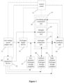
- Figure 1 is a schematic diagram of an ammonia synthesis system based on a fluctuating hydrogen source according to an embodiment of the present disclosure.
- Reference numeral 11 represents a new energy power supply unit
- 10 represents a combined compression system
- 01 represents a hydrogen supply device
- 02 represents an air separation device
- 03 represents a hydrogen compressor unit
- 05 represents a circulating gas compressor unit
- 06 represents an ammonia synthesis unit
- 07 represents a low-pressure hydrogen storage container
- 08 represents a medium-pressure hydrogen storage container
- 09 represents a high-pressure hydrogen storage container
- 12 represents a control center.
- the overall ammonia synthesis system based on the fluctuating hydrogen source includes:
- the ammonia synthesis system based on the fluctuating hydrogen source provided by the present disclosure can solve the problem of energy loss during hydrogen storage and reuse in the ammonia synthesis process with hydrogen generation by unstable green electricity.
- the ammonia synthesis system based on the fluctuating hydrogen source includes the combined compression system 10, the hydrogen supply device 01, the new energy power supply unit 11, the air separation device 02, the ammonia synthesis unit 06, the low-pressure hydrogen storage container 07, the medium-pressure hydrogen storage container 08 and the high-pressure hydrogen storage container 09.
- the combined compression system 10 is provided with the hydrogen compressor unit 03, the nitrogen compressor unit 04 and the circulating gas compressor unit 05; where the hydrogen compressor unit 03 is provided with the above gas inlet, the gas outlet and an equal pressure bidirectional flow pipeline.
- the gas inlet (hydrogen inlet) is connected to the hydrogen supply device 01.
- the nitrogen compressor unit 04 is provided with the gas inlet and the gas outlet, the above gas inlet (nitrogen inlet) is connected to the air separation device 02.
- the circulating gas compressor unit 05 is provided with a circulating gas inlet and a circulating gas outlet, where the circulating gas inlet of the circulating gas compressor unit 05 is connected to the circulating gas outlet of the ammonia synthesis unit 06, and the circulating gas outlet of the circulating gas compressor unit 05 is connected to the circulating gas inlet of the ammonia synthesis unit 06.
- the hydrogen supply device 01 is configured for hydrogen generation.
- the pressure of hydrogen generated by the hydrogen supply device preferably ranges from 1.5MPa to 4.5MPa.
- the new energy power supply unit 11 provides electric energy for the hydrogen supply device 01.
- the new energy power supply unit includes, but is not limited to, a wind power new energy power supply unit, a photovoltaic new energy power supply unit or a hydropower new energy power supply unit.
- the key point of the present disclosure is to provide an ammonia synthesis system based on a fluctuating hydrogen source, which can provide an energy-saving, stable and reliable technology for the hydrogen storage process in the field of ammonia synthesis with hydrogen generation by green electricity, to provide an energy-saving solution to overcome technical difficulty and the contradictions between the instability of green electricity hydrogen generation and the high stability of hydrogen sources required by traditional ammonia synthesis.
- the air separation device 02 is configured for nitrogen generation and is provided with an air inlet and a nitrogen outlet.
- the air separation device 02 is connected to the gas inlet of the nitrogen compressor unit 04 through the nitrogen outlet.
- the air separation device 02 includes a nitrogen generation device and/or a backup nitrogen system, where the nitrogen generation device is configured to provide nitrogen for the hydrogen storage container and the nitrogen outlet under normal conditions, and the backup nitrogen system is configured to provide nitrogen to the hydrogen storage container and the nitrogen outlet in a case that the nitrogen generation device is shut down, so as to maintain the normal operation of the ammonia synthesis system.
- the pressure of the high-pressure nitrogen after being increased by the nitrogen compressor unit 04 preferably ranges from 14MPa to 22MPa.
- the ammonia synthesis unit 06 is configured to produce ammonia, and the ammonia synthesis unit 06 is provided with a hydrogen inlet, a nitrogen inlet, a circulating gas outlet and a circulating gas inlet, where the ammonia synthesis unit 06 is connected to the gas outlet of the hydrogen compressor unit 03 through the hydrogen inlet, and is connected to the gas outlet of the nitrogen compressor unit 04 through the nitrogen inlet; the circulating gas outlet and the circulating gas inlet of the ammonia synthesis unit 06 are respectively connected to the circulating gas compressor unit 05.
- the low-pressure hydrogen storage container 07, the medium-pressure hydrogen storage container 08 and the high-pressure hydrogen storage container 09 are respectively connected to the air separation device 02.
- the low-pressure hydrogen storage container 07 is connected to the hydrogen outlet of the hydrogen supply device 01
- the medium-pressure hydrogen storage container 08 is directly connected to the position between segments of the hydrogen compressor unit 03
- the high-pressure hydrogen storage container 09 is connected to the gas outlet of the hydrogen compressor unit 03.
- the hydrogen flows into the corresponding hydrogen storage container from the corresponding connecting pipeline until the pressures of the two are equal; in a case that the pressure in the corresponding hydrogen storage container is greater than the pressure in the corresponding connecting pipeline, the hydrogen flows from the corresponding hydrogen storage container into the corresponding connecting pipeline until the pressures of the two are equal.
- the low-pressure hydrogen storage container 07 preferably is a vertical pressure vessel or a spherical pressure vessel, where a storage pressure thereof is applicable to various types of electrolytic hydrogen generation processes such as ALK, PEM, AME, and the like.
- the hydrogen storage pressure ranges from 1.5MPa to 4.5MPa.
- the hydrogen can flow in both directions in the pipeline between the low-pressure hydrogen storage container 07 and the gas inlet of the hydrogen compressor unit 03 to reach an equal pressure.
- the medium-pressure hydrogen storage container 08 preferably is a vertical high-pressure hydrogen storage container.
- Medium-pressure hydrogen is drawn from a position between segments of the hydrogen compressor unit of the ammonia synthesis system, where the hydrogen storage pressure preferably ranges from 6MPa to 12MPa.
- the hydrogen can flow in both directions between the medium-pressure hydrogen storage container 08 and the position between segments of the hydrogen compressor unit 03 to reach an equal pressure. It can be understood that, the compression of the hydrogen compressor unit 03 is divided into at least two segments (or called stages).
- the high-pressure hydrogen storage container 09 preferably is a high-pressure hydrogen storage pipe bundle.
- the hydrogen storage pressure meets technical requirements of various traditional ammonia synthesis processes.
- the hydrogen storage pressure ranges from 12MPa to 22MPa.
- the hydrogen can flow in both directions in the pipeline between the high-pressure hydrogen storage container 09 and the gas outlet of hydrogen compressor unit 03 to reach an equal pressure.
- the above high-pressure hydrogen storage, medium-pressure hydrogen storage and low-pressure hydrogen storage are coupled in the present disclosure.
- the most technically and economically optimal hydrogen storage solution can be provided for various types of ammonia synthesis scenarios, which can not only ensure the technical reliability of new energy hydrogen generation for ammonia synthesis, but also ensure an optimal technical-economic efficiency.
- hydrogen storage with different levels can effectively solve problems of system pressure stability in the process from electrolytic hydrogen generation, hydrogen pressurization configured for synthesis gas and hydrogen usage reduce the impact of fluctuations on equipment and devices, and thereby improving the service life of the devices.
- the air separation device 02 can respectively ensure a stable output of hydrogen of the low-pressure hydrogen storage container 07, the medium-pressure hydrogen storage container 08 and the high-pressure hydrogen storage container 09 by supplementing nitrogen, to ensure the stable supply of hydrogen, which is preferably realized through the nitrogen generation device of the air separation device 02.
- Isobaric hydrogen storage process in a case that the hydrogen in the hydrogen storage container is reused, the nitrogen from the nitrogen supply device, for example the air separation device 02, is introduced into the hydrogen storage container from a bottom thereof to maintain a release pressure of the reused hydrogen by making use of the characteristic that the density of nitrogen being greater than the density of hydrogen so as to achieve an energy-saving effect of the hydrogen storage and reuse process.
- the nitrogen introduced into the system during the isobaric hydrogen storage process is finally mixed with hydrogen and enters the ammonia synthesis unit 06, and the insufficient nitrogen amount is supplemented and precisely controlled by the nitrogen compressor unit 04.
- the ammonia synthesis system with green electricity hydrogen generation and isobaric energy-saving hydrogen storage further includes a control center 12 configured to control the operation of the combined compression system 10, the hydrogen supply device 01, the new energy power supply unit 11, the air separation device 02 and the ammonia synthesis unit 06 separately.
- ammonia synthesis system based on the fluctuating hydrogen source provided by the present disclosure has following beneficial effects.
- the present disclosure provides the ammonia synthesis system based on a fluctuating hydrogen source, including: a hydrogen supply device, where a fluctuating amount of hydrogen is provided by the hydrogen supply device; a hydrogen storage container, configured to store the hydrogen provided by the hydrogen supply device; a nitrogen supply device, configured to communicate with the hydrogen storage container to introduce nitrogen into the hydrogen storage container to maintain a stable pressure in the hydrogen storage container.
- the ammonia synthesis system based on a fluctuating hydrogen source provided by the present disclosure can not only meet requirements of application scenarios where synthesis gas is produced from conventional raw material, but also be well applied to application scenarios where the hydrogen supply for ammonia synthesis fluctuates, for example, the application scenarios where raw material hydrogen for ammonia synthesis is obtained from hydrogen generation by unstable green electricity (with regular and irregular fluctuations) such as wind power, photovoltaic power and hydropower, and even in the case that the green electricity fluctuates in the full load range of 0-100%, the stable production of synthetic ammonia can also be ensured.
- unstable green electricity with regular and irregular fluctuations
- the system provided by the present disclosure can achieve 100% reuse rate of gaseous hydrogen storage without decompression, that is, there is no pressure loss in hydrogen storage for reuse, thus effectively ensuring technical economy and operation and maintenance economy of the device.
- a technical solution of a control method for an ammonia synthesis system based on a fluctuating hydrogen source is further provided according to the present disclosure, where the ammonia synthesis system is the above ammonia synthesis system.
- the control method is applied to the control center of the ammonia synthesis system.
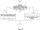
- step S110 whether the pressure in the hydrogen storage container of the ammonia synthesis system is less than a preset pressure value is determined.
- step S 120 In a case that the pressure of the hydrogen storage container is less than the preset pressure value, step S 120 is to be performed first, and then return to perform step 110; in a case that the pressure of the hydrogen storage container is greater than or equal to the preset pressure value, step S 130 is to be performed.
- the preset pressure value is a pressure value of the hydrogen storage container in a case that the ammonia synthesis system can operate normally, which can be set according to actual needs, and is specifically limited herein, which are all within the scope of protection of the present disclosure.
- step S120 the nitrogen supply device of the ammonia synthesis system is controlled to introduce nitrogen into the hydrogen storage container.
- step S130 the nitrogen supply device of the ammonia synthesis system is prevented from introducing nitrogen into the hydrogen storage container.
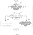
- control method for an ammonia synthesis system based on a fluctuating hydrogen source is further provided according to the present disclosure, and the specific process is shown in Figure 3
- the control method according to this technical solution further includes the following steps before the above step S110.
- step S210 whether the amount of hydrogen provided by the hydrogen supply device of the ammonia synthesis system fluctuates is determined.
- step S 110 is performed first; in a case that the amount of hydrogen provided by the hydrogen supply device does not fluctuate, step S110 is not performed.
- the amount of hydrogen provided by the hydrogen supply device is stable; and in a case that the new energy power supply unit connected to the ammonia synthesis system operates at low load or shuts down due to failure, the amount of hydrogen provided by the hydrogen supply device fluctuates.
- step S310 whether a ratio of hydrogen to nitrogen in the hydrogen and nitrogen introduced into the ammonia synthesis unit of the ammonia synthesis system is greater than a set ratio is determined.
- step S320 In a case that the ratio of hydrogen to nitrogen is greater than the set ratio, step S320 is to be performed; in a case that the ratio of hydrogen to nitrogen is less than or equal to the set ratio, step S330 is to be performed.
- step S320 according to a difference between the ratio of hydrogen to nitrogen and the set ratio, an amount of nitrogen introduced by the nitrogen supply device to the ammonia synthesis unit is increased.
- the ammonia synthesis system includes a nitrogen compressor unit
- the amount of nitrogen introduced by the nitrogen supply device to the ammonia synthesis unit is increased by increasing a workload of the nitrogen compressor unit.
- step S330 according to the difference between the ratio of hydrogen to nitrogen and the set ratio, the amount of nitrogen introduced by the nitrogen supply device to the ammonia synthesis unit is reduced.
- the ammonia synthesis system includes a nitrogen compressor unit
- the amount of nitrogen introduced by the nitrogen supply device to the ammonia synthesis unit can be reduced by reducing the workload of the nitrogen compressor unit.
- Figure 1 is a schematic diagram of an ammonia synthesis system based on a fluctuating hydrogen source according to an embodiment of the present disclosure; where reference numeral 11 represents a new energy power supply unit, 10 represents a combined compression system, 01 represents a hydrogen supply device, and 02 represents an air separation device, 03 represents a hydrogen compressor unit, 04 represents a nitrogen compressor unit, 05 represents a circulating gas compressor unit, 06 represents an ammonia synthesis unit, 07 represents a spherical low-pressure hydrogen storage container, 08 represents a vertical high-pressure hydrogen storage container, 09 represents a high-pressure hydrogen storage pipe bundle, and 12 represents a control center.
- reference numeral 11 represents a new energy power supply unit
- 10 represents a combined compression system
- 01 represents a hydrogen supply device
- 02 represents an air separation device
- 03 represents a hydrogen compressor unit
- 04 represents a nitrogen compressor unit
- 05 represents a circulating gas compressor unit
- 06 represents an ammonia synthesis unit
- 07 represents a spherical low-pressure hydrogen storage container
- the green electricity produced by the new energy power supply unit 11 is sent to the hydrogen supply device 01, and qualified low-pressure hydrogen (1.5MPa) is produced through power conversion equipment and hydrogen generation equipment.
- the hydrogen After entering the spherical low-pressure hydrogen storage container 07 for storage and buffering, the hydrogen enters the hydrogen compressor unit 03 of the combined compression system 10 for pressurization, the hydrogen is pressurized to 8.5MPa through the first-stage (first segment) compression, enters the vertical high-pressure hydrogen storage container 08 for storage and buffering, and then enters the second segment of the hydrogen compressor unit 03 to be pressurized through the second-stage (second segment) compression to the pressure of 16.5 MPa, which is the pressure required by the ammonia synthesis, the hydrogen is then sent to the high-pressure hydrogen storage pipe bundle 09 for storage and buffering, and mixed with high-pressure nitrogen (16.5 MPa) from the air separation device 02 and being pressurized by the nitrogen compressor unit 04, and then enters the ammonia synthesis unit 06 for the ammonia synthesis reaction, and finally the product am
- the low-pressure nitrogen (0.4 MPa) generated by the air separation device 02 is pressurized by the nitrogen compressor unit 04 of the combined compression system 10, and then mixed with the high-pressure hydrogen from the hydrogen compressor unit 03 and the hydrogen, which is stored for reuse, of the high-pressure hydrogen storage pipe bundle 09, after precise adjustment and allocation of components, the ammonia synthesis gas is sent to the ammonia synthesis unit 06.
- the nitrogen generated in the air separation device 02 is introduced into the bottom of the spherical low-pressure hydrogen storage container 07, the vertical high-pressure hydrogen storage container 08 and the high-pressure hydrogen storage pipe bundle 09 respectively, to supplement nitrogen to each of the hydrogen storage containers in time in a case that stored hydrogen is to be reused, so as to ensure stable pressure of the reused hydrogen.
- the ammonia synthesis reaction is a cyclic reaction.
- the synthesis gas that passes through the reactor in a single time is only partially converted into ammonia.
- the unconverted synthesis gas, after the product ammonia is separated, is called the circulating gas, and the circulating gas is returned to the ammonia synthesis system for re-reaction after being pressurized by the circulating gas compressor unit 05.
- Low-pressure, medium-pressure and high-pressure hydrogen storage containers are equipped with complete and reliable pressure indication alarms to monitor hydrogen pressure in real time.
- the hydrogen supply device 01, air separation device 02, combined compression system 10 and ammonia synthesis unit 06 in the technological process are all operating stably at full load, and the spherical low-pressure hydrogen storage container 07, the vertical high-pressure hydrogen storage container 08 and the high-pressure hydrogen storage pipe bundle 09 are filled with hydrogen of corresponding pressures respectively, and the entire ammonia synthesis system with new energy hydrogen generation operates stably to produce the product ammonia.
- the backup nitrogen system of the air separation device 02 is in a standby state, and supplementary nitrogen of the spherical low-pressure hydrogen storage container 07, the vertical high-pressure hydrogen storage container 08 and the high-pressure hydrogen storage pipe bundle 09 is in a cut off state.
- the main equipment of the air separation device 02 reduces its load accordingly, and the backup nitrogen system of the air separation device 02 is started, to ensure the stable supply of nitrogen to the entire system.
- the hydrogen supply device 01 correspondingly reduces the load according to the power supply situation.
- the nitrogen replenishment systems at the bottom of the spherical low-pressure hydrogen storage container 07, the vertical high-pressure hydrogen storage container 08 and the high-pressure hydrogen storage pipe bundle 09 are started to ensure that the hydrogen in each hydrogen storage container is stably injected into the main process system from the container, to ultimately ensure the combined compression system 10 and the ammonia synthesis unit 06 continue to stably operate at full load for a certain period of time, where the period time of stable operation at full load is determined by the capacity of the spherical low-pressure hydrogen storage container 07, the vertical high-pressure hydrogen storage container 08 and the high-pressure hydrogen storage pipe bundle 09.
- the production load of the main process system can be adjusted (automatically or manually), to ensure long-term stable operation of the system.
- a shutdown signal is sent to the control center 12.
- the hydrogen supply device 01 stops due to the loss of power supply, and the hydrogen generation is stopped;
- the main equipment of the air separation device 02 stops due to the loss of power supply, and the backup nitrogen system of the air separation device is started, to ensure the stable supply of nitrogen to the entire system.
- the nitrogen replenishment systems at the bottoms of the spherical low-pressure hydrogen storage container 07, the vertical high-pressure hydrogen storage container 08 and the high-pressure hydrogen storage pipe bundle 09 are started to ensure that the hydrogen in each hydrogen storage container is stably injected into the main process system from the container, to ensure the safe operation of the entire system.
- the combined compression system 10 and the ammonia synthesis unit 06 adjust the production load until the system safely shuts down.
- the ammonia synthesis system is adjusted from 100% load operation to 70% load operation.
- an interlocking stop signal for the entire ammonia synthesis system with new energy hydrogen generation is sent by the control center 12, and the system stops safely.
- the ammonia output is maintained at more than 70% of the rated output, the purity is 99.9%wt, and the yield is 99.98%.
Landscapes
- Chemical & Material Sciences (AREA)
- Organic Chemistry (AREA)
- Chemical Kinetics & Catalysis (AREA)
- Engineering & Computer Science (AREA)
- Inorganic Chemistry (AREA)
- Analytical Chemistry (AREA)
- Automation & Control Theory (AREA)
- Metallurgy (AREA)
- Electrochemistry (AREA)
- Materials Engineering (AREA)
- Toxicology (AREA)
- General Health & Medical Sciences (AREA)
- Health & Medical Sciences (AREA)
- General Engineering & Computer Science (AREA)
- Mechanical Engineering (AREA)
- Combustion & Propulsion (AREA)
- Filling Or Discharging Of Gas Storage Vessels (AREA)
- Hydrogen, Water And Hydrids (AREA)
Applications Claiming Priority (1)
| Application Number | Priority Date | Filing Date | Title |
|---|---|---|---|
| CN202310140551.7A CN116081645B (zh) | 2023-02-13 | 2023-02-13 | 一种基于波动性氢气源的合成氨系统及其控制方法 |
Publications (1)
| Publication Number | Publication Date |
|---|---|
| EP4414329A1 true EP4414329A1 (fr) | 2024-08-14 |
Family
ID=86206319
Family Applications (1)
| Application Number | Title | Priority Date | Filing Date |
|---|---|---|---|
| EP23212022.0A Pending EP4414329A1 (fr) | 2023-02-13 | 2023-11-24 | Système de synthèse d'ammoniac basé sur une source d'hydrogène fluctuante et son procédé de commande |
Country Status (4)
| Country | Link |
|---|---|
| US (1) | US20240270586A1 (fr) |
| EP (1) | EP4414329A1 (fr) |
| CN (1) | CN116081645B (fr) |
| AU (1) | AU2023270269B2 (fr) |
Families Citing this family (5)
| Publication number | Priority date | Publication date | Assignee | Title |
|---|---|---|---|---|
| CN116730359A (zh) * | 2023-07-17 | 2023-09-12 | 南京凯普索工程有限公司 | 一种柔性控制的绿色能源制氨系统及绿色能源制氨方法 |
| CN117446822A (zh) * | 2023-09-21 | 2024-01-26 | 阳光氢能科技有限公司 | 合成氨系统、合成氨控制方法、控制装置及电子设备 |
| CN117419275A (zh) * | 2023-12-06 | 2024-01-19 | 中能建氢能源有限公司 | 一种固态储氢与氮气的混合储存系统以及运行方法和应用 |
| CN118221134B (zh) * | 2024-03-28 | 2026-04-14 | 福州大学 | 一种绿色合成氨系统及其控制方法 |
| CN119303511A (zh) * | 2024-10-21 | 2025-01-14 | 长春吉电氢能有限公司 | 一种合成氨设备及合成氨方法 |
Citations (4)
| Publication number | Priority date | Publication date | Assignee | Title |
|---|---|---|---|---|
| CN216191111U (zh) * | 2021-10-14 | 2022-04-05 | 于一夫 | 一种氨智能合成系统 |
| EP3837213B1 (fr) * | 2018-08-17 | 2022-04-27 | Yara International ASA | Procédé d'acide nitrique à haute valorisation énergétique utilisant un fluide contenant de l'oxygène liquide |
| EP4053653A1 (fr) * | 2021-03-05 | 2022-09-07 | Air Products and Chemicals, Inc. | Procédé et appareil de surveillance des caractéristiques de fonctionnement d'un complexe industriel gazier |
| CN115117936A (zh) * | 2022-07-28 | 2022-09-27 | 清华四川能源互联网研究院 | 电制氢合成氨方法及系统 |
Family Cites Families (2)
| Publication number | Priority date | Publication date | Assignee | Title |
|---|---|---|---|---|
| CN110425416B (zh) * | 2019-08-15 | 2023-08-15 | 浙江浙能技术研究院有限公司 | 一种小规模低能耗阶梯储氢系统及方法 |
| CN112952872B (zh) * | 2021-04-16 | 2024-07-30 | 山东大学 | 一种风-氢氨-热电蓄能调峰联合发电系统和方法 |
-
2023
- 2023-02-13 CN CN202310140551.7A patent/CN116081645B/zh active Active
- 2023-11-22 AU AU2023270269A patent/AU2023270269B2/en active Active
- 2023-11-24 EP EP23212022.0A patent/EP4414329A1/fr active Pending
- 2023-12-11 US US18/535,938 patent/US20240270586A1/en active Pending
Patent Citations (4)
| Publication number | Priority date | Publication date | Assignee | Title |
|---|---|---|---|---|
| EP3837213B1 (fr) * | 2018-08-17 | 2022-04-27 | Yara International ASA | Procédé d'acide nitrique à haute valorisation énergétique utilisant un fluide contenant de l'oxygène liquide |
| EP4053653A1 (fr) * | 2021-03-05 | 2022-09-07 | Air Products and Chemicals, Inc. | Procédé et appareil de surveillance des caractéristiques de fonctionnement d'un complexe industriel gazier |
| CN216191111U (zh) * | 2021-10-14 | 2022-04-05 | 于一夫 | 一种氨智能合成系统 |
| CN115117936A (zh) * | 2022-07-28 | 2022-09-27 | 清华四川能源互联网研究院 | 电制氢合成氨方法及系统 |
Also Published As
| Publication number | Publication date |
|---|---|
| US20240270586A1 (en) | 2024-08-15 |
| AU2023270269B2 (en) | 2025-08-28 |
| CN116081645B (zh) | 2025-06-17 |
| AU2023270269A1 (en) | 2024-08-29 |
| CN116081645A (zh) | 2023-05-09 |
Similar Documents
| Publication | Publication Date | Title |
|---|---|---|
| EP4414329A1 (fr) | Système de synthèse d'ammoniac basé sur une source d'hydrogène fluctuante et son procédé de commande | |
| EP3957772B1 (fr) | Procédé pour générer, stocker et utiliser de l'hydrogène | |
| US20230341180A1 (en) | Method and device for manufacturing liquid hydrogen by offshore off-grid superconducting wind turbine | |
| CN111692520B (zh) | 一种供应气体的方法 | |
| CN115479034A (zh) | 用于对具有可变流动速率的原料气进行压缩的方法和设备 | |
| EP4332694A1 (fr) | Procédé et système de commande de production et de stockage de gaz industriels | |
| CN111692521B (zh) | 一种高效灵活的多模式加氢站 | |
| CN209313452U (zh) | 一种高效率高安全风电制氢调峰调频系统 | |
| CN117175679A (zh) | 一种风力光伏及氢燃料电池联合发电系统及控制方法 | |
| CN118166374A (zh) | 一种适用于现场制氢加氢站的碱性电解水制氢系统 | |
| CN114383381A (zh) | 一种联合生产绿氢绿氧及冷能利用方法 | |
| RU2564308C1 (ru) | Способ эксплуатации промышленной установки по производству мочевины, содержащей несколько систем | |
| AU2022203965B2 (en) | Process and apparatus for operating a compression system | |
| CN216972696U (zh) | 一种合成气定比生产系统 | |
| EA048279B1 (ru) | Система синтеза аммиака, основанная на пульсирующем источнике водорода, и способ управления этой системой | |
| EP4404409A1 (fr) | Procédé et appareil de gestion de puissance dans une installation de production de gaz industriel | |
| US20250038540A1 (en) | Partial load shedding for achieving full regenerative supply of elctric loads | |
| CN118353047A (zh) | 一种变压储氢调峰风电的工艺及控制方法 | |
| CN110425416A (zh) | 一种小规模低能耗阶梯储氢系统及方法 | |
| CN222795746U (zh) | 一种可恒压使用的碱性水电解槽的氢氧排气系统 | |
| CN220669148U (zh) | 一种大规模高压储氢供氢装置 | |
| CN221297086U (zh) | 一种碱性电解水制氢系统低负荷状态下氧中氢含量的控制系统 | |
| CN223499928U (zh) | 一种甲醇生产系统 | |
| CN120328580A (zh) | 一种储氢分氨一体式系统及方法 | |
| CN222209958U (zh) | 一种带储氢支路的绿氢供应系统 |
Legal Events
| Date | Code | Title | Description |
|---|---|---|---|
| PUAI | Public reference made under article 153(3) epc to a published international application that has entered the european phase |
Free format text: ORIGINAL CODE: 0009012 |
|
| STAA | Information on the status of an ep patent application or granted ep patent |
Free format text: STATUS: REQUEST FOR EXAMINATION WAS MADE |
|
| 17P | Request for examination filed |
Effective date: 20231124 |
|
| AK | Designated contracting states |
Kind code of ref document: A1 Designated state(s): AL AT BE BG CH CY CZ DE DK EE ES FI FR GB GR HR HU IE IS IT LI LT LU LV MC ME MK MT NL NO PL PT RO RS SE SI SK SM TR |
|
| STAA | Information on the status of an ep patent application or granted ep patent |
Free format text: STATUS: EXAMINATION IS IN PROGRESS |
|
| 17Q | First examination report despatched |
Effective date: 20250429 |